1999 HONDA CIVIC Ground
[x] Cancel search: GroundPage 1060 of 2189
Inspection and Adjustment
Steering Operation
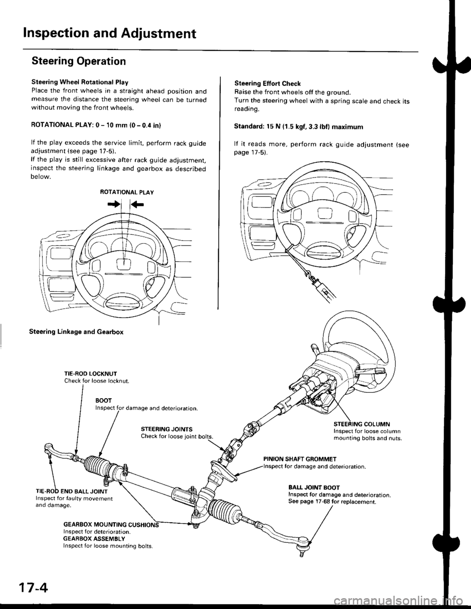
Steering Wheel Rotational Play
Place the front wheels in a straight ahead position andmeasure the distance the steering wheel can be turnedwithout moving the front wheels.
ROTATIONAL PLAY: 0 - 10 mm (0 - 0.4 in)
lf the play exceeds the service limit, perform rack guide
adjustment (see page lT-5).
lf the play is still excessive after rack guide adjustment,inspect the steering linkage and gearbox as descrjbed
Detow.
Steering Linkage and Gearbox
TIE.ROO LOCKNUTCheck for loose locknut.
BOOTInspect for damage and deterioration.
STEERING JOINTSCheck for loose joint
END BALL JOINTInspect for faulty movementano oamage.
GEABBOX MOUNTINGInspect f or deterioration.GEABBOX ASSEMBLY
Ste€ring Effort Check
Raise the front wheels off the ground.
Turn the steering wheel with a spring scale and check itsreaorng,
Standard: 15 N (1.5 kgf, 3.3 lbll maximum
lf it reads more. perform rack guide adjustment (see
page 17-5).
COLUMNInspect for loose columnmounting bolts and nuts.
PINION SHAFT GROMMETfor damage and deterioration.
BALL JOINT BOOTInspect for damage and deterioration.See pago 17-68 tor replacement.
ao-\---------U
17-4
Inspect for loose mounting bolts.
Page 1131 of 2189
Wheel/Hub Inspection
\
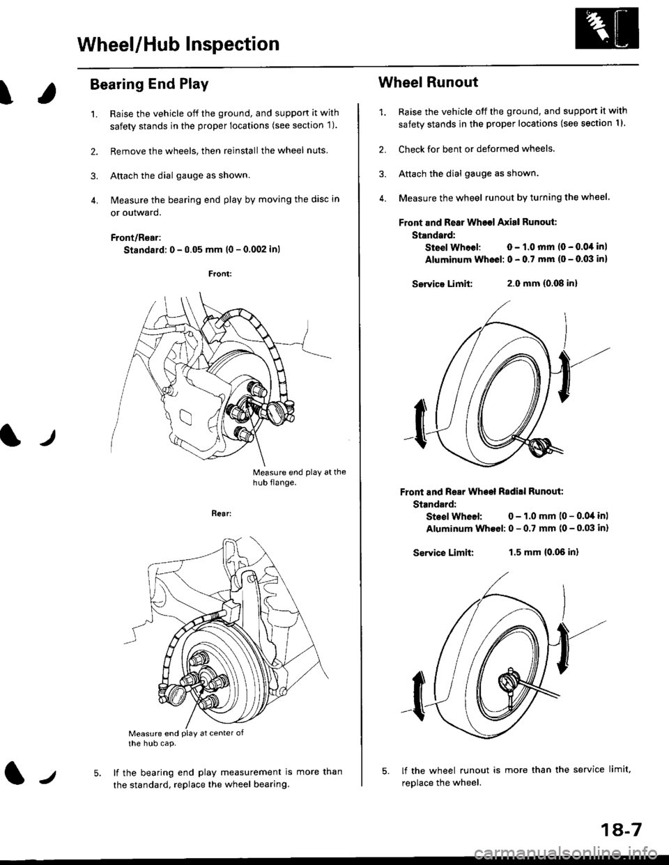
Bearing End Play
1. Raise the vehicle off the ground, and suppon it wjth
safety stands in the proper locations (see section 1).
2. Remove the wheels, then reinstallthe wheel nuts
3. Attach the dial gauge as shown.
4. N4easure the bearing end play by moving the disc in
or outward.
Front/R€ar:
Standard: 0 - 0.05 mm l0 - 0.002 inl
Measure end play athub flange.
t./
Bear:
Measure end PlaY at center ofthe hub cap.
lf the bearing end play measurement is
the standard, replace the wheel bearing.lJmore than
1A-7
Wheel Runout
1. Raise the vehicle off the ground, and support it with
safety stands in the proper locations (see section I I
2. Check for bent or deformed wheels.
3. Attach the dial gauge as shown.
4. Measure the wheel runout by turning the wheel.
Front and Rear Wheel Axisl Runout:
Standard:
Steel Whoel: 0 - 1.0 mm (0 - 0.0,1 inl
Aluminum Wheel: 0 - 0.7 mm (o - 0.03 in)
Servica Limit:2.0 mm (0.08 inl
Front and Rear Wheel Radill Runout:
Standard:
Steol Wheel: 0 - 1.0 mm (0 - 0.04 in)
Aluminum Wheol: 0 - 0.7 mm (0 - 0.03 in)
Service Limit:1.5 mm {0.06 in}
lf the wheel runout is more than the service limit,
replace the wheel.
Page 1132 of 2189
Front Suspension
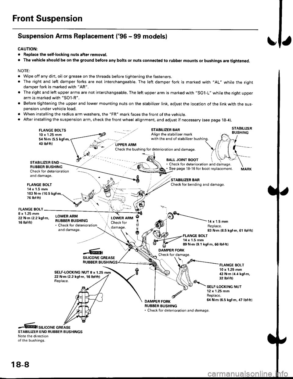
Suspension Arms Replacement ('96 - 99 models)
CAUTION:
. Replace the selt-locking nuts after removal.
. The vehicle should be on the ground betore any bolts or nuts connected to rubber mounts or bushings are tightened.
NOTE:
. Wipe off any dirt, oil or grease on the threads before tightening the fasteners.. The right and left damper forks are not interchangeable. The left damper fork is marked with "AL" while the rightdamper fork is marked with "AR'
. The right and left upper arms are not interchangeable. The left upper arm is marked with "SO1-L" while the right upperarm is marked with "SOl-R".
. Before tightening the upper and lower mounting nuts on the stabilizer link, adjust the location of the link with the sus-pension under vehicle load.
. When installing the radius arm washers, the "FR" mark faces the front ofthe vehicle.. After installing the suspension arm, ch eck the front wheel alignment, and adjust if necessary (see page 18-4).
FLANGE BOLTS10 x 1.25 mm54 N.m 15.5 kgl.m,40 tbf.ftl
STAEILIZER ENDRUBBER BUSHING
BALL JOINT BOOT. Check for deterioration and damage.. See page 18-16 for boot replacement.
STABILIZER BARCheck for bending and damage.
Check for deterioration - ---\--
and damage, -\
FLANGE BOLT14 x 1.5 mm/)l103 N.m {10.5 kg{.m,. t, ,/4,76lb{.ft) t,,"-iV
v:\FLANGE BOLT-
;iffillr-"- ilHitffi*::,"*"
and damaoe,
o.'-----------14 x 1.5 mmReplace.83 N.m {8.5 kgf.m, 61 lbf.ftl
LOWER ARMCheck for
c
JlTTda
1{ x 1.5 mm89 N.m {9.1 kgt m. 66 lbtft)
-6;SILICONE GREASERUBBER BUSHING
DAMPER FORKCheck for damage.
SELF-LOCKING NUT I x 1.2522 N.m (2.2 kg{.m, 16lbf.ftlReplace.
FLANGE BOLT10 x 1.25 mm€ N.m {4.6 kgt m.32 tbf.ft)
SELF-LOCKING NUT12x 1.25 mmReplace.6it N m {6.5 kgf.m, 47 lbf.ftl
RUEBER BUSHING. Check for deterioration and damage.
.6t",.,"o".c"KeSTAAIL|zER END RUBBER EUSHINGSNote the directionof the bushings.
18-8
Page 1133 of 2189
I
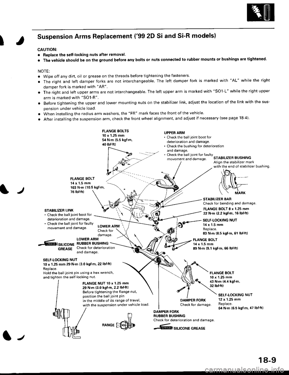
Suspension Arms Replacement ('99 2D Si and Si-R models)
CAUTION:
. Replace the selt-locking nuts after removal.
. The vehicle should be on the ground belore any bolts or nuts connected to rubber mounts or bushings are tightened.
NOTE:
. Wipe off any dirt, oil or grease on the threads before tightening the fasteners
. The right and ieft damper forks are not interchangeable. The left damper fork is marked with "AL" while the right
damper fork is marked with "AR"
. The right and left upper arms are not interchangeable. The left upper arm is marked with "SOl-L" while the right upper
arm is marked with "SO1-R".
. Before tightening the upper and lower mounting nuts on the stabilizer link, adiust the location of the link with the sus-
pension under vehicle load.
. When installing the radius arm washers, the "FR" mark faces the front of the vehicle.
. After installing the suspension arm, check the front wheel alignment, and adjust if necessary (see page 18-4).
FLANGE BOLTS10 x 1.25 mmsit N.m 15.5 kgf.m,40 tbtftl
UPPER ARM' Check the ball joint boot fordeterioration and damage.. Check the bushing for deteriorationano oamage,. Check the ball ioint fo. faultymovement and clamage.STABILIZER BUSHINGAlign the stabilizer markwith the end of stabilizer bushing
FLANGE BOLT14 x 1.5 mm
l./
103 N.m (10.5 kgf.m,76 tbr.ftl
STABILIZER LINK. Check the ballioint bootfordeterioration and damage.. Checkthe ballioint tor faultymovement and damage.
STABILIZER BARCheck for bending and damage.
FLANGE BOLT 8 x 1.25 mm22 N.m (2.2 kgf.m, 16lbf.ft)
SELF-LOCKING NUT14 x 1.5 mmReplace.83 N.m 18.5 kgf m, 61 lbf.ft)
-.6r srr-,co", hSHrtlrT.[*"u
6g619g Check for deteriorationano oamage.
SELF.LOCKING NUT10 x 1.25 mm 29 N m 13.0 kgf m, 22 lbf ftl
Replace.Hold the ball ioint pin using a hex wrench,
and taghten the self'locking nut.
LOWER ARMCheck fordamage.
FLANGE NUT l0 x 1.25 mm
29 N.m 13.0 kgI m,2.2 lbf ft)
Before tightening the {lange nut,position the ball joint Pinin the middle of its range of travel,
with the suspension under vehicle load
FLANGE BOLT14 x 1.5 mm89 N.m 19.1 kgf.m, 66 lbf.ft)
FLANGE BOLT10 x '1.25 mm43 N.m {4.4 kgf.m,32 tbtft)
DAMP€R FORKCheck lor damage.
DAMPER FORKRU88ER BUSHINGCheck for deterioration and damage.
4@lsrlrcoNE GREASE
SELF.LOCKING NUT12 x 1.25 mmReplace.64 N m 16.5 kgl.m, 47 lblft)
J
RANGE
18-9
Page 1134 of 2189
Front Suspension
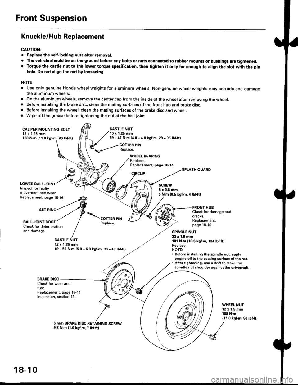
Knuckle/Hub Replacement
CAUTION:
. Replaco tho salf-locking nuts after romoval.
. The vehiclo should be on tho ground bsfore any bohs or nuls connected to rubber mounb or bushings are tightened.. Torqu€ th€ castle nut to the lowor torque specification, ihen tighton it only far enough to align th€ slot whh the pin
hole. Do not align the nut by loosening.
NOTE:
. Use only genuine Honda wheel weights for aluminum wheels. Non-genuine wheel weights may corrode and damagethe aluminum wheels.
. On the aluminum wheels, remove the center cap from the inside of the wheel after removing the wheel,. Before installing the brake disc, clean the mating surfaces of the front hub and brake disc,. Before installing the wheel, clean the mating surfaces of the brake disc and wheel.o Wipe off the grease before tightening the nut at the ball joint.
CALIPER MOUNTING BOLT12 x 1.25 mm108 N.m {11.0 kgl.m, 80lbf.ft)
LOWER BALL JOINTInspect for faultymovement and wear.
CASTLE NUT10 r 1.25 mm39 - ia7 N.m (4.0 - 4.8 kgf.m, 29 - 35 lbf,ftl
COTTER PINReplace.
WHEEL BEARINGReplace.Replacement, page 18-14
CIRCLIP
SCREW5x0.8mm5 N.m {0.5 ksl.m, 4 lbf.ftlReplacement, page 18-16
SET RING
BALL JOINT BOOT
FRONT HUBCheck for damage andcracks.Replacement,page 18-10Check for deteriorationand damage.
CASTLE NUT12 x 1.25 mm49 - 59 N.m l5.O - 6.0 kg{.m. 36 - /(} lbf,ftl
SPINDI.T ]{UT22 r 1.5 mmlEl N.m {18.5 kgf.rn, 13{ lbl.ttlReplace.NOTE:. Before instelling the spindle nut. apply6n9ine oilto th6 seating surface ofthe nut.. Atter tightening, uso a drift to stake thespindle nut should6r against the driveshaft.
BRAKE DISCCheck for wear andrust.Replacement, page 18-11lnspection, section 19.
WHEEL NUT12 x 1.5 mm'108 N.m1r1.0 kgf.m, 8lt lbf.ft)
6 mm BRAKE DISC RETAINING SCREW9.8 N.m 11.0 kgf.m, 7 lbtft)
18-10
Page 1145 of 2189
Rear Suspension
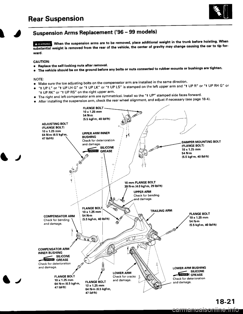
ISuspension Arms Replacement ('96 - 99 modelsl
tffi Whsn ths suspension arms ar6 to be removed. place additionsl weight in the trunk bafore hoisting' Wh€n
-substantial weight is removed ftom th6 teal of ths vehicl6, the center of gravity may change causing ths cat to tip tor'
ward.
CAUTION:
. Replace the selt-locking nuts after removal.
.Thgvehic|eshouldb€onthggroundboforeanybohsornutsconnectodtorubbelmountso]bughingsaretighton.
NOTE:
. Make sure the toe adjusting bolts on the compensator arm are installed in the same direction'
. ,,t UP 1,, or ,,t UP LH G,. or ,.t UP LK,, or "t UP LS'. is stamped on the |eft upper arm and ,,t UP R" or "t UP RH G., or
"t UP RK" or "t UP RS" on the right upper arm'
. The rightand left "ornp"n""to, uitt rre symmetrical lnstall sothe "t UP" stamped side faces forward'
.Afterinsta||ingthesuspens|onarm,checktherearwhee|alignment,andadjustifnecessary(seepagelS-4).
FLANGE BOLT10 x 1.25 mm54 N.m
ADJUSTING BOLT(FLANGE BOLTI10 x 1.25 mm
BUSHINGCheck for deteriorationand oamage.
(5.5 kgf'm, 40 lbf'ftl
UPPER ARM INNER
47 tbf.ftl
tJ
l0 mm FLANGE BOLT
N.m t4.0 kst m, 29lblftl
DAMPER MOUNTING BOLT(FLANGE BOLT}
10 x 1.25 mm
54Nm(5.5 kgd.m, iro lbf'ft)
FI.ANGE BOLT10 x 1,25 mm54 N.m(5,5 ksrf.m, 4{} lbf'ft}
UPPER ARMCheck for bendangdamage-
TRAILING ARM
COMPENSATOR ARM
Check for bendingano oamage,
COMPENSATOR ARM
INNER BUSHING
.- SILICONE.@] GREASE
Check tor deteriorataonand damage.
FLANGE BOLT10 x 1.25 mm64 N.m {6.5 kgt'm,47 lbf.ft)
LOWER ARMCheck for cracksano damage.
LOWEN ARM BUSHING
.,- SILICONE..i@l GREASECheck for deteriorationand oamage,FLANGE AOLT12 x 1.25 mm64 N.m {6.5 kgf m,47 tbf.ftt
FLANGE BOL10 x 1.25 mm
I 54 N.m
(5.5 ksrm, ao lbf'ftl
1A-21
Page 1160 of 2189
Inspection and Adjustment
Parking Brake
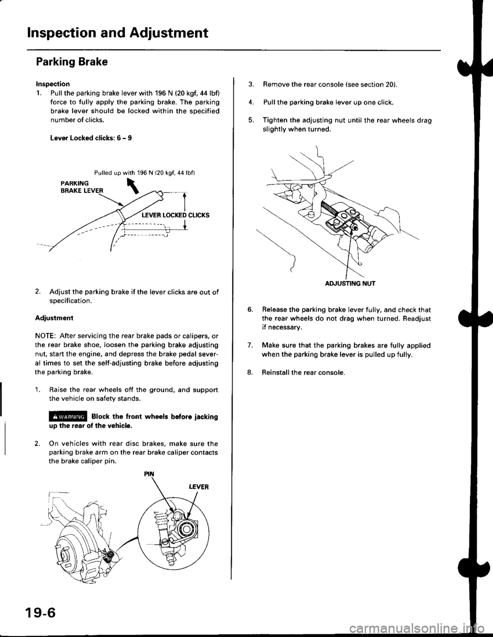
Inspection
1. Pull the parking brake lever with 196 N {20 kgf. 44 lbf)
force to fully apply the parking brake. The parking
brake lever should be locked within the sDecified
number of clicks.
Lever Locked clicks: 6 - I
Pulled up96 N 120 kgf,44lbf)
2. Adjust the parking brake if the lever clicks are out of
specification.
Adiusiment
NOTE: After servicing the rear brake pads or calipers, or
the rear brake shoe, loosen the parking brake adjusting
nut, start the engine, and depress the brake pedal sever-
al times to set the self-adjusting brake before adjusting
the parking brake.
1. Raise the rear wheels off the ground, and support
the vehicle on safety stands.
l@ Elock the front wheels bofore iackinguD the rear ot the v6hicle.
2. On vehicles with rear disc brakes, make sure theparking brake arm on the rear brake caliper contacts
the brake calioer Din.
with 1
\
19-6
Remove the rear console (see section 20).
Pullthe parking brake lever up one click,
Tighten the adjusting nut until the rear wheels drag
slightly when turned.
Belease the parking brake lever fully, and check that
the rear wheels do not drag when turned. Readjust
if necessarv.
Make sure that the parking brakes are fully applied
when the parking brake lever is pulled up fully.
Reinstall the rear console.
7.
8.
ADJUSTING NUT
Page 1205 of 2189
ABS Control Unit Terminal Arrangement
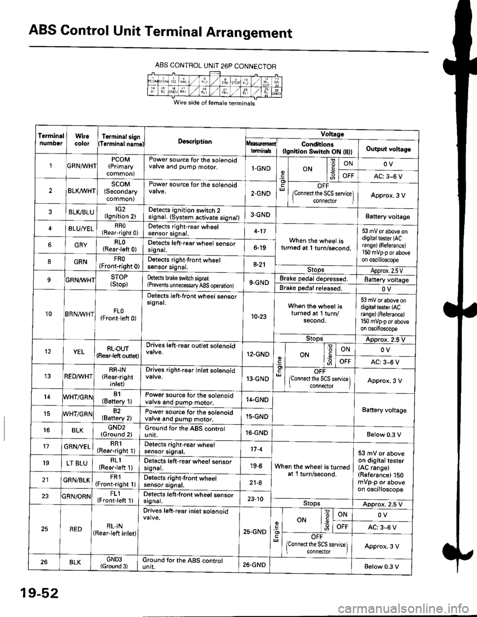
ABS CONTROL UNIT 26P CONNECTOR
Wire side of temale terminals
Terminalnumo0rWirecolorTerminal signTerminalnamoDgscriptionVoltage
Conditions(lgnition Switch ON flt))Output voltagoteminals
PCOM(Primary
common)
Power source for the solenoidvalve and pump motor.1-GNDON
=ONOV
AC: 3-6 V
BLK/WHTscoM(Secondary
common)
Power source for the solenoid
2.GNDOFF
lConnect the SCS service\
conneclor lApprox. 3 V
ELVBLUtG2(lgnition 2)Detects ignition switch 2
!9nal. (system activate signal)3-GNDBatt€ry voltage
BLU/YELRRO(Rear-right 0)Detects right-rear wheelsensor signal.4-17
When the wheel isturned at 1 turn/second.
53 mV or above ondigitaltester (ACra nge) {Fefera nce)150 mvp-p or aboveon oscilloscope
6GRYRLO(Rear-left 0)Detects left-rear wheel sensorsrgnal.6-19
8GRNFRO(Front-right 0)D€tects right-front wheelsgnsor srgnal,a-21StopsApprox.2.5VSTOP(Stop)hects brake switch signal.(Prevents unnecess€ry ABS operation)9-GNDBrake pedal depressed.Battery voltage
Brake pedal released.OV
10BRN^/vHTFLO(Front-left 0)
Detects left-front wheel sensorsignal.
10-23
When the wheel isturned at 1 turn/secono.
53 mV or above ondigitaltester (ACrange) (Referance)
150 mVFporaboveon oscilloscope
9!opsApprox. 2.5 V
12YELRLOUT(Rearjeft outlet)
Drives left-rear outlet solenoid
12.GNDON-9ONOV
OFFAC: 3^6 V
REDMHTRR]N(Rear-right
inlet)
Drives right-rear inlet solenoidvalve.13-GNDOFF
lconnect the SCS service]i connector IApprox. 3 V
14B1(Battery 1)Power source for the solenoidvatve and pump motor.14.GND
Battery voltage15WHT/G R N82(Baftery 2)Power source for the solenoidvarve ano pump motor.15.GND
r6BLKGND2{Ground 2)Ground for the ABS controlunit.16-GNDBelow 0.3 V
17GRN/'/ELRR1(Rear-right 1)Detects right-rear wheelsensor signal.17-4
When the wheel is turnedat 1 turn/second.
53 mV or aboveon digitaltester(AC range)(Referance) 150mVp-p or aboveon oscilloscope
19LT BLURLl(Rea.-left 1)Detects left-rear wheel sensorsagnal.19-6
GRN/BLKFRl(Front-right 1)Detects right-front wheelsensor signal.21-8
FL1(Front-left 1)Detects left-front wheel sensorsignal.23-10StopsApprox. 2.5 V
REDRL-IN(Rear-lett inletl
Drives left-r€ar inlet solenoid
25.GND
ut
ON
'6
-9ONOV
OFFAC: 3-6 V
OFF
lconnect the SCS service] connector lApprox. 3 V
BLKGND3(Ground 3)Ground for the ABS cgntrolunit.26.GNDBelow 0.3 V
19-52