Page 960 of 2189

Troubleshooting Flowchart - Secondary Gear Shaft Speed Sensor
NOTE: Record all freeze data before you troubleshoot
Po$ible Causo
. Oisconnectod secondarY gear
shaft speed sensor conn66or' short or open in secondary gear
shaft spe€d sensor wiro. Faulty secondarY gear 3haft
sPeed sensor
SECONDARY GEAR SHAFT
SPEEO SENSOR CONNECTOR
Terminal side of male terminals
PCM CONNECTOR D I15P)
VEL (WHT/REO) VEL SG IALK/WHTI
Wire side oI female terminals
(cont'd)
14-243
' OBD ll Scan Tool indicates
Code P1888.. Self-diagnosis E indicalor light
indicats Code 35.
Check the secondarY gear shaft
speed sensor installation, and
check it for damage.
ls the secondary gear shaft
speed sensor installedproperly, and not damaged?
Reinatall or replace and rocheck.
Measure SocondarY Gear Sh.ft
Speed Sen3or Resistance at the
Sensor Connector:1. Disconnect the 2P connector
trom the secondary gear shaft
speed sensor.2. Measure secondary gear shaft
speed sensor resistance at the
sensor connector.
ls the resistance 350 - 600 0?
Check SecondarY Gear Shaft
Speed Sensor lor a Short Circuit:
1. Disconned the D (16P) connec-
tor from the PCM.
2. Check for continuity between
body ground and the D1 ter-
minal and D7 terminal indi-
vidually.
Repair short in the wiros
b.tween the Dl and D7 termi_
ne13 and th€ secondarY geal
3haft lpeed sonsor.
To page 14-284
Page 965 of 2189

Electrical Troubleshooting ('99 - 00 Models)
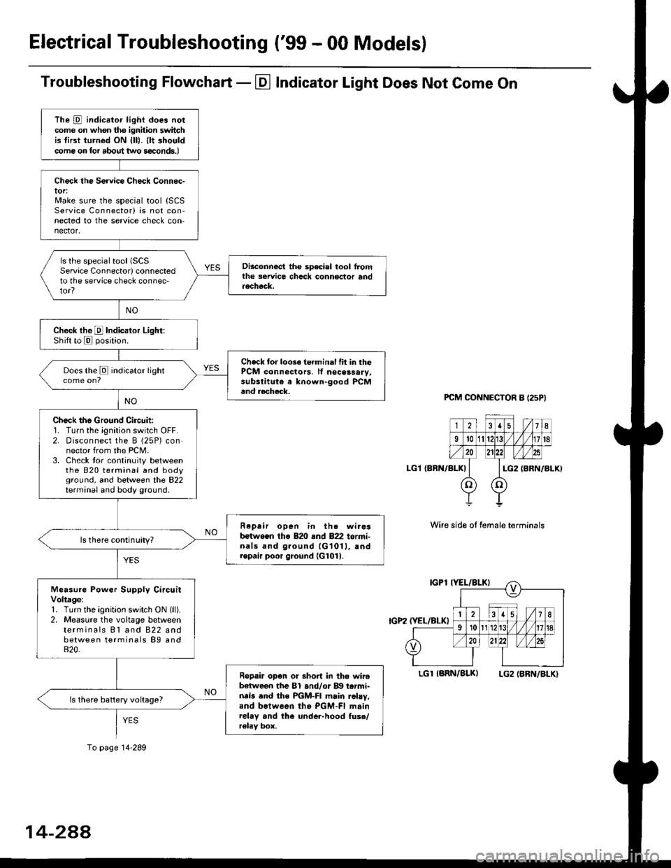
Troubleshooting Flowchart - El Indicator Light Does Not Come On
PCM CONNECTOR B I25PI
LGl {BRN/BLK)
Wire side ot female terminals
LGlIARN/BLK) LG2IBRN/BLKI
The D indicator light does notcome on whon ths ignhion switchis tirst turned ON {lll. llt shouldcome on tor about two s€conds.)
Check the Service Check Connec-tor:Make sure the special tool {SCSService Connectorl is not connected to the service check con-nector,
ls the special tool (SCS
Service Connectorl connectedto the service check connec-tor?
Disconnect the sp€cial tool f]omthe seruice chcck connoclor andaecheck.
Check the E Indicalor Light:Shift to E posjtion.
Check tor loose te.minal fit in thePCM connectors, lf nocessary,substitute a known-good PCMand aecheck.
Does the E indicator light
Check the Ground Circuit:1. Turn the ignition switch OFF.2. Disconnect the B (25P) connector from the PCM.3. Check tor continuity betweenthe 820 terminal and bodyground, and between the 822terminal and body ground.
Fepair open in th. wirosb€tw.en the 820 end 822 termi-nals and ground {G1011, !ndrepair poor ground {G1011.
ls there continuity?
Measure Power Supply CircuitVoltage:1. Turn the ignitlon switch ON (ll).
2. Measure the voltage betweenterminals Bl and 822 andbetween terminals B9 and820.
Ropair op€n or short in tho wireb€tween the Bl and/or B!| tarmi-nds and the PGM-FI main .ohy,and between tho PGM-FI mainrelay and the under-hood fuso/r€lav box.
ls there battery voltage?
To page 14-289
14-2AA
Page 966 of 2189
From page 14-289
Msaaure D IND Volt.ge:1. Turn the ignition switch OFF.
2. Connect tho B (25Plconnector
to the PCM.
3. Connect a digital multimeter
to the D14 and 820 or 822 ter-
mtnals.il. Turn the ignition switch ON(lll, and make sure that voltage
is available for two seconds
Check for open in the wire
between tha D14 terminal rnd
the gauge a33emblY. lf wiro ia
OK, chock for . frulty indicator
light bulb or a Iaulty gaug.
a3r6mbly printod circuit board.
Check D IND for a Short Circuit:
Check lor continuitY between the
D14 terminal and body ground.
Rgpair 3hort in the wire b.tween
the D14 tcrminal and tho gauge
a*somblY.
Check for loose terminsl fh in the
PCM connectors Check tho A/T
goar posilion switch. It neces'
saiy, iubstitute a known_good
PCM rnd rochock.
PCM CONNECTORS
D {16P1
(BRN/BI.X)D4 IND (GRN/BLK}
Wire side of female terminals
123rs 1/7I215
910nn fT /fl6l112
o lzlzz ,rl/zs 1311- -T---=4'+:l
LG2IBRN/BLKI\=/ |
r lz35
6i /l/t01112
l0
D' IND
o
IGRN/BLKI
4-289
Page 967 of 2189

ElectricalTroubleshooting ('gg - 00 Models)
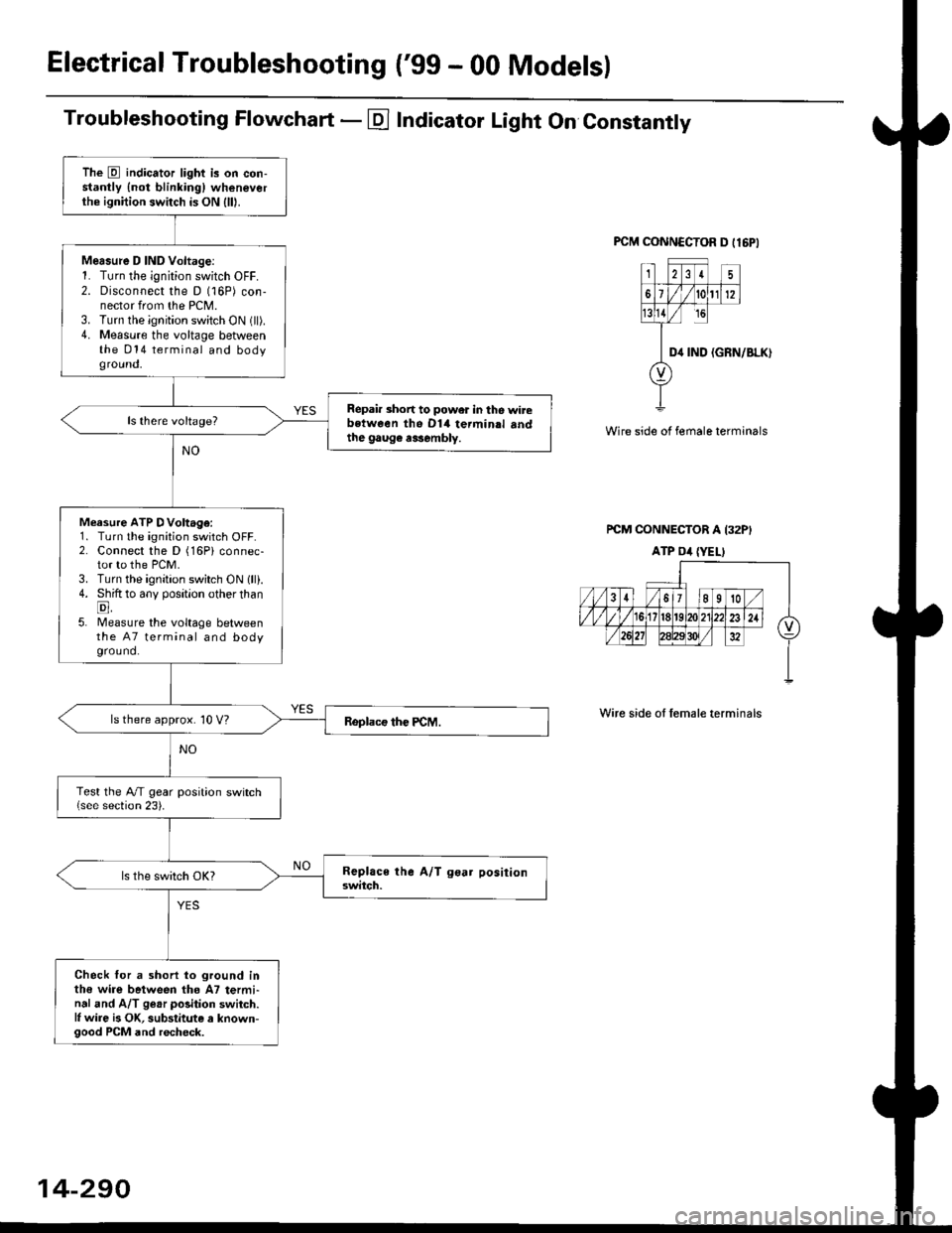
Troubleshooting Flowchart - E Indicator Light On Constantly
FCM CONNCCTOR D tl6PI
23I5
61t012
tsll / rc
II D4 rND
o
(GRN/BLK)
Wire side of female terminals
rcM CONNECTOR A I32PI
ATP Dil {YELI
Wire side of lemale terminals
The E indicator light is on con-stantly {not blinkingl wheneverthe ignition switch is ON lll|.
Mersure D IND Voltage:1. Turn the ignition switch OFF.2. Disconnect the D (16P) con-nector from the PCM.3. Turn the ignition switch ON (ll).4. Measure the voltage betweenthe 014 terminal and bodyground,
Repair short to power in tho wirebstween the Dl4 termin.l sndthe gaug€ r3sembly.
Measure ATP DVoltage:1. Turn the ignition switch OFF.2. Connect the D (16Pi connec-tor to the PCM.3. Turn the ignition switch ON lll).4. Shift to any position other thanE,5. lMeasure the voltage betweenthe 47 terminal and bodyground.
ls there approx. 10 V?
Test the A/T gear position switch{see section 23).
Check for a shorl lo ground inthe wire between tho A7 termi-nal and A/T ge.r polition switch.l, wire is OK, substitute a known-good PCM and recheck.
14-290
Page 968 of 2189

Linear Solenoids/lnhibitor Solenoid
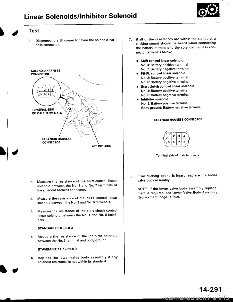
)Test
1. Disconnect the 8P connector from the solenoid har-
ness connector.
SOLENOID HARNESSCONNECTOR
ATF OIPSTICK
Measure the resistance of the shift control linear
solenoid between the No. 3 and No. 7 terminals of
the solenoid harness connector.
Measure the resistance of the PH-PL control linear
solenoid between the No. 2 and No. 6 terminals
Measure the resistance of the start clutch control
linear solenoid between the No 4 and No. 8 termi-
nats,
STANDARD:38-6.8O
Measure the resistance of the inhibitor solenoid
between the No. 5 terminal and body ground
STANDARD:11.7 - 21.0 O
Replace the lower valve body assembly if any
solenoid resistance is not within its standard.
7. lf all ot the resistances are within the standard, a
clicking sound should be heard when connectrng
the batterv terminals to the solenoid harness con-
nector terminals below:
Shift control linear solsnoid
No.3: Batterv Positive terminal
No. 7: Battery negative terminal
PH-PL control linear solenoid
No.2: Batterv oositive terminal
No. 6: Baftery negative terminal
Start clutch control linear solenoid
No. 4: Battery Positive terminal
No.8: Battery negative terminal
lnhibitor solsnoid
No,5: Batterv Positive terminal
Body ground: Battery negative termrnal
SOLENOID HARNESS CONNECTOR
Terminal side of male terminals
lf no clicking sound is heard, replace the lower
valve body assemblY,
NOTE: lf the lower valve body assembly replace-
ment is required, see Lower Valve Body Assembly
Replacement (page 14-302).
14-291
Page 976 of 2189

Fluid Level
l.Checking/Changing
CAUTION: while chscking and changing, be sure not to
allow dust and other toreign particles to ent€l inlo the
transmission.
Checking
NOTE: Check the fluid level with the engine at normal
operating temperature (the radiator fan comes on).
'1. Park the vehicle on the level ground. Turn oft the
engrne.
2. Remove the dipstick (yellow loop) from the trans-
mission, and wipe lt with a clean cloth.
NOTE: Check the transmission fluid 50 to 90 sec-
onds after shutting off the engine.
3. Insert the diDstick into the transmission.
DIPSTICK (YELLOW LOOPI
Remove the dipstick and check the fluid level.
should be between the uDDer and lower mark.DIPSTICK
5. lf the level is below the lower mark, add fluid into
the filler hole to bring it to the upper mark. Use
Genuine Honda CW Fluid only.
6. Insert the dipstick into the transmission.
14-299
Changing
1. Bring the transmission up to normal operating tem-
perature (the radiator fan comes on) by driving the
vehicle. Park the vehicle on the level ground, and
turn off the engine.
2. Bemove the drain plug, and drain the CVT fluid.
NOTE| lf a cooler flusher is to be used, see page 14-
352 and 14-353.
Reinstall the drain plug with a new sealing washer,
then refill the transmission with Genuine Honda
CVT Fluid to the upper mark on the dipstick.
Automatic Transmission Fluid CaPacity:
3.9 i (4.r US qt. 3.4 lmp qt) 8t chlnging
6.4 I (6.8 US qt, 5.6 lmp qt) 8t ov€lhaul
Rscommended Automatic Transmission Fluid:
Genuine Honda CVT Fluid-
Use Genuine Honda CW fluid only. Using other flu-
ids can affect transmission operation and may
reduce transmission liJe.
Change Interval:
Normal Condition: 30, 000 miles 148,000 km)
Severe Condition: 30,000 miles (48,000 km), but it
you drive at high sPeeds in high
t90"F (32'C) and abovol temper-
atures, the ttansmission fluid
should be changed evsrY 15,000
miles 124,000 km).
{-]lr
ORAIN PLUG18 x 1.5 mma9 N.7n (5.0 kgl.m, 36 lb{'ftl
SEALING WASHERReplace.
Page 981 of 2189

Transmission
Removal
@. Mako suro lifts. iacks, and satety stands are placod
properly, and hoi3t bracket are attached to lhe cor-
rect position on the engine {see soction 1}.
. Apply parking brake and block r€ar wheels so tha
vehicle will not roll off stands and fall on you while
working undor it.
CAUTION: Use tender covers to avoid damaging painted
surfaces.
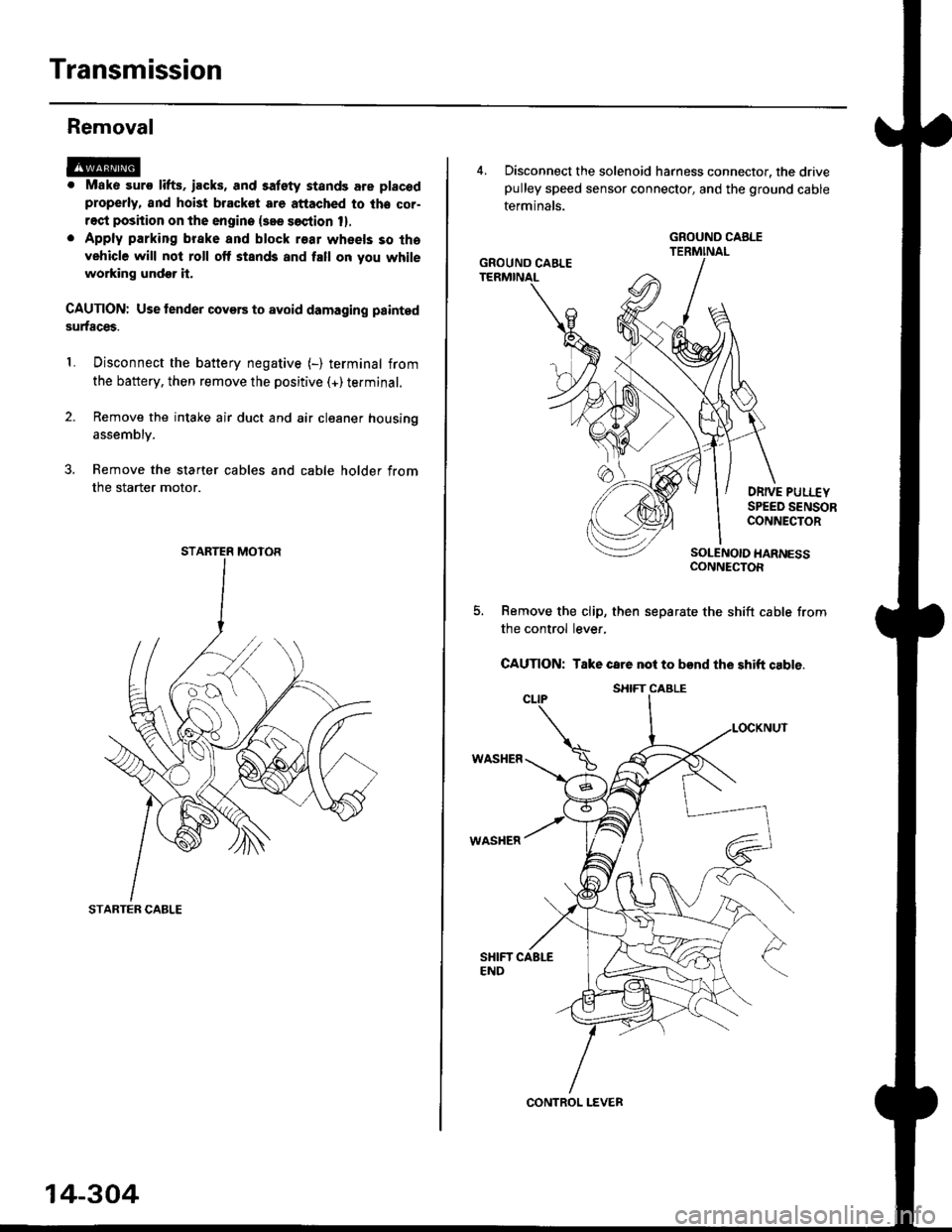
Disconnect the battery negative (-) terminal from
the battery, then remove the positive (+)terminal.
Remove the intake air duct and air cleaner housing
1.
assembly.
3. Remove the starter cables and cable holder from
the starter motor.
STARTER CABLE
STARTER MOTOR
14-304
4, Disconnect the solenoid harness connector, the drivepulley speed sensor connector, and the ground cable
terminals.
DRIVE PULI.-EYSPEED SENSORCONNECTOR
SOLENOIO HARNESSCONNECTOR
Remove the clip, then separate the shift cable from
the control lever,
CAUTION: Take care not to bend the shift cable.
WASHER
WASHER
GROUND CABLE
GROUND CAELE
CONTROL LEVER
S}IIFT CABLE
Page 1027 of 2189

22. Install the shift cable end on the control lever, and
install the shift cable on the shift cable bracket'
CAUTION: Take care not to bend the shift cable'
23. lnstall the clip in the direction shown.
LOCKNUT
SHIFI CABLE 29 N m {3.0 kg{ m, 22lblftl
SHIFT CABLEERACKET
WASHERIPLASTIC)
CONTROL LEVER
24, Connect the solenoid harness connector. the drive
pulley speed sensor connector. and the ground
cable terminals.
6x1.0mm12 N.m {1.2 kgf.m.8,7 rbtft)
GROUND CABLETERMINAL 6x1.0mm
GROUNDTERMINAL
12 N.m {1.2 kgf'm,8.7lbtfrl
DRIVE PULLEYSPEED SENSORCONNECTOR
SOLENOID HARNESS
CONNECTOR
25. Connect the starter motor cable on the starter motor.
and install the cable holder.
NOTE: When installing the staner motor cable. make
sure that the crimped side of the ring terminal is
facing out (see section 23).
STARTEB
BMOUNTING NUT
9 N.m (0.9 kgf m,7 lbf ft)
26. Install all removed connectors and clamps'
27. Install the distributor.
28. Install the intake air duct and air cleaner housing
29.
assemDly.
Refill the transmission with the recommended
Genuine Honda CVT Fluid (see page 14-2991
CAUTION: While filling the CvT Fluid, bs surs not io
allow dust and other fotoign particles to entor into
the transmission.
Connect the battery positive (+) terminal first, then
the negative (-l terminal to the battery'
Check the ignition timing (see section 23).
Start the engine. Set the parking brake, and shift the
transmission through all gears three times Check
shift cable adjustment (see page 14-355).
Check the front wheel alignment (see section 18)
Let the engine reach operating temperature (the
radiator fan comes on) with the transmission in lXl
or E position, then turn it off and check fluid level'
Perform the start clutch calibration procedure on
page 14-293.
Road test as described on pages 14-296 and 14-297
30.
31.
34.
36.
STARTER MOTOR
14-351