1999 HONDA CIVIC Timing belt cover
[x] Cancel search: Timing belt coverPage 119 of 2189

VTEC Rocker Arms
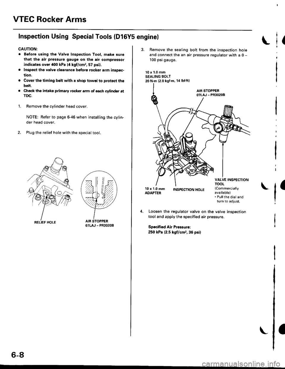
Inspection Using SpecialTools (Dl6Y5 enginel
CAUTION:
. Before using th6 Valve Inspection Tool, make 3ure
that ths air pressure gaugo on the air comptsssor
indicates over iloo kPa 14 kgf/cmr, 57 psi).
. Inspecl th6 valv€ clearance beforo rocker atm insDec"
tion,
'1.
Cover the timing belt with a shop towel to protect tho
belt.
Check ths intakg primaty rocker arm of each cylindqr atTDC.
Remove the cylinder head cover.
NOTE: Refer to page 6-46 when installing the cylin-
der head cover.
Plug the relief hole with the special tool.
YY
OTLAJ - PR3O2OB
(
3, Remove the sealing bolt from the inspection holeand connect the an air pressure regulator with a 0 -
100 psi gauge.
10 x 1.0 mmSEALING BOLT20 N.m {2.0 kgj'm. 14lblft}
l
I
'10 x 1.0 mmADAPTER;NSp€CTTONHOLE (Commercially
available)
l'Pullthe dial andturn to adlust,
Loosen the regulator valve on the valve inspection
tool and apply the specified air pressure.
Spocified Air Pressurei
250 kPa {2.5 kg,t/cm,,36 psi}
o-at
Page 121 of 2189

VTEC Rocker Arms
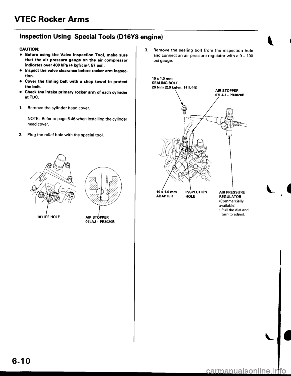
Inspection Using Special Tools (D16Y8 enginel
CAUTION:
o Before using the Valve Inspection Tool. mak6 surethat the air pressure gauge on the air comprsssor
indicates ovor 400 kPa {4 kgf/cm,, 57 psil.
. Inspect th6 valve clearanco before rockar arm inspec-
tion.
. Cov€r th€ timing belt with a shop towel to protect
the bolt.
. Check tho intake prima.y rockff arm of each cylindel
at TDC.
1.Remove the cylinder head cover.
NOTE: Refer to page 6-46 when installing the cylinder
neao cover,
Plug the relief hole with the specialtool.
OTLAJ - PR3O2OB
I,^ A IAo- tu
3. Remove the sealing bolt from the inspection hole
ancl connect an air pressure regulator with a 0 - 100psi gauge.
l0 x 1.0 mmSEALING EOLT20 N.m (2.0 kgf.m, 14 lbf.ft)
(AIR PRESSUREREGULATOR
{Commerciallyavailable). Pullthe dialandturn to adjust,
Page 128 of 2189

Timing Belt
Illustrated lndex
NOTE:
. Refer to page 6-20 for how to position the crankshaft and pulley before installing the belt.
. Mark the direction of rotation on the belt before removing.
a Do not use the upper cover and lower cover for storing removed items,
. Clean the upper cover and lower cover before installing.
. Replace the ca mshaft seals and cra n kshaft sea ls if there is oil leakage.
. Refer to page 6-16 before installing the timing belt.
CYLINDER HEADCOVERReler to page 6-46when installing.
HEAD COVEB GASKETReplaco when l6akin9,domaged or deteriorated.Apply liquid gasket at
th€ lour corners of thetecessos.
d
@
TIMING BELTInspection, page 6-18Adjustment, page 6-18Removal, page 6-19Installation. page 6-20
I x 1.25 mm3t N.m {3.8 kgf'm, 27 lbfftl
Apply engine oilto the bolt
thleads.
CRANKSHAFT SPEED FI.UCTUATION
lcr(Fl sENsoRReplacement, Page 6-22
UPPER COVEB
lnstallwithsurface facing in.
TIMING BELTDRIVE PULLEYReplacement, page 6_16
6x1.0mm9.8 N'm 11.0 kgt m,7.2 tbf.ft)NUBBER SEALSReplace when damagedor deledorated.
LOWER COVER
FUBBERPLUG
CRANKSHAFT PULLEYReplacement, page 6'16
PULLEY BOLTlil x 1.25 mm20 N.m 12.0 kgt.m,14 lbt'ft) + 90"Replacement, page 6'16Do not us6 an impactwrench when installing.
x 1.0 mmBOLT o-RING10 x 1,25 mm Reolace.14 N.m {,1.5 kgt m, 33 lbt ftl
6x1.0mmt2 N.m 11.2 kgf'm,8.7 tbt f0
9.E N'm (1.0 kgt.m,?.2 tbf.ftl\.-,o
6-17
Page 129 of 2189

Timing Belt
Inspection
1.
2.
3.
Remove the cylinder head cover.
. Refer to page 6 46 when installing.
Remove the upper cover (see page 6 19).
Inspect the timing belt for cracks and oil or coolantsoakrng.
NOTE:
. Replace the belt if oil or coolant soaKeo.. Remove any oil or solvent that gets on the belt.
Rotate pulleyand inspect belt.
After inspecting, retorque the crankshaft pullev bolt{see page 6- 16).
o- I6
Tension Adjustment
CAUTION: lt*ays aa;j"t the timing bett rension withthe engine cold.
NOTE:
. The tensioner is spring loaded to apply tension to thebelt automatically after making the following adjustment.
. Always rotate the crankshaft counterclockwise whenviewed from the pulley side. Rotating it clockwisemay result in improper adjustment of the belt ten-sion.
. lnspect the timing belt before adjusting the belt ten-ston.
1.Remove the cylinder head cover.
. Refer to page 6,46 when installing.
Remove the upper cover (see page 6,'19).
Rotate the crankshaft five or six revolutions to setthe belt.
Set the No. 'l piston at TDC (see page 6-21).
Loosen the adjusting bolt 180'.
2.
3.
4.
5.
\I
ADJUSTING BOLT44 N.m {4.5 kgt m,33 rbf.ft)
7.
8.
Rotate the crankshaft counterclockwise three teethon the camshaft pulley.
Tighten the adjusting bolt.
After inspecting, retorque the crankshaft pulley bolt(see page 6-16).
Page 130 of 2189

Removal
NOTE:
. Replace the timing belt at 105,000 miles (168.000 km)
according to the maintenance schedule (normal con-
ditions/severe conditions).
lf the vehicle is regularly driven in one or more of the
followlng conditions, replace the timing belt at 60.000
miles (U.S.A.) 100,000 km {Canada).
.In very high temperatures (over 110'F.43'C)
. In very low temperatures (under -20'F, -29"C)'
! Turn the crankshaft pulley so the No. 1 piston is at
top dead center (TDC) before removing the belt (see
page 6'21).
. Inspect the water pump before installing the timing
belt {see Page 10-14).
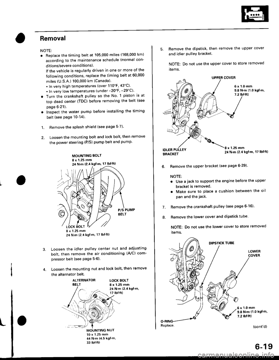
1. Remove the splash shield (see page 5-7).
2. Loosen the mounting bolt and lock bolt. then remove
the power steering (P/S) pump belt and pump
MOUNTING BOLT
8 x 1.25 mm2il N m 12.4 kgl m, 17 lbf'ft)
P/S PUMPBELT
I x 1.25 mm24 N m (2.4 kgf m, 17 lbt ft)
Loosen the idler pulley center nut and adjusting
bolt, then remove the air conditioning (AVC) com-
pressor belt (see Page 5-6).
Loosen the mounting nut and lock bolt, then remove
the alternator belt.
ALTERNATORBELTLOCK BOLTI x 1.25 mm24 N.m 12.4 kgf.m,r? tbI.ft)
3.
MOUNTING NUT10 x 1.25 mm44 N.m 14.5 kgl m,
33 rb{ ft)
5. Remove the dipstick, then remove the upper cover
and idler PulleY bracket
NOTE: Do not use the upper cover to store removed
items.
6x1.0mm9.8 N.m 11.0 kgf.m,7.2
IDLERI x 1.25 mm24 N.m (2.4 kgl.m, 17 lbf'ft)BRACKET
6. Remove the upper bracket {see page 6-29)
NOTE:
. Use a jack to support the engine before the upper
bracket is removed
. Make sure to place a cushion between the oil
pan and the jack.
Remove the crankshaft pulley (see page 6-16).
Remove the lower cover and dipstick tube
NOTE; Do not use the lower cover to store removed
items.
1.
.'.
DIPSTICK TUBE
LOWER
6x1.0mm9.8 N.m (1.0 kgf m,
7.2 rbt.ft)
(cont'd)
6-19
Replace.
Page 132 of 2189

3. Install the timing belt tightly in the sequence shown'
OTiming belt drive pullev (crankshaft) )@Adjusting
pulley -towater pump pulley J@Camshatt pulley'
NOTE: Make sure the timing belt drive pulley and
camshaft PulleY are at TDC
7.
Loosen and retighten the adiusting bolt to tension
the timing belt.
lnstall the lower cover and upper cover.
NOTE: Clean the upper and lower covers before
installation.
lnstall the crankshaft pulley, then tighten the pulley
bolt (see page &16)
Rotate the crankshaft pulley about five or six turns
counterclockwise so that the timing belt positions
on the Pulleys.
Adjust the timing belt tension (see page 6-18).8.
L
9. Check that the crankshaft pulley and camshaft pul-
ley are both at TDC.
CRANKSHAFT PULLEY:
CAMSHAFT PULLEY:
lf the camshaft and crankshaft pulleys are not posi-
tioned at TDC, remove the timing belt and adjust
the position following the procedure on page 6-20'
Then reinstall the timing belt.
After installation, adjust the tension of each belt
. See section 23 for alternator belt tension adjust-
ment.
a See section 22 tot NC compressor belt tension
adjustment.
. See section 17 for P/S pump belt tension adjust
ment,
(wHrTE)
"UP" MARK
TDC MARK
11.
6-21
Page 141 of 2189

Cylinder HeadRocker Arms
18.
19.
21.
22.
Removal (cont'd)
Remove the timing belt {see page 6-19).
Remove the camshaft pulley and back cover,
CAMSHAFTPULLEYClean when installing.
6x1.0mm8 x 1.25 mm37 N.m (3.8 kgf.m,21 tbtlrlApply engine oilto thebolt threads.
Remove the exhaust manifold {see pages 9-6 and 9_7).
Remove the intake manifold (see pages 9-2 thru 4).
Remove the cylinder head bolts, then remove thecylinder head.
CAUTION: To pr€vent warpage, unsclew lhe bohsin sequonce 1/3 turn at a time; rgpeat tho sequenceuntil all bolts are loosened.
CYLINDER HEAD BOLTS LOOSENING SEOUENGE:
6-30
Removal
1. Loosen the adjusting screws.
2. Unscrew the camshaft holder bolts, then,removethe rocker arm assembly.
NOTE:
a Unscrew the camshaft holder bolts two turns at at,me, in a crisscross pattern, to prevent damao_ing the valves or rocker arm assembly.. When removing the rocker arm assembly, do notremove the camshaft holder bolts. The bolts willkeep the camshaft holders, the springs and therocker arms on the shaft.
CAMSHAFT HOLDER BOLTS LOOSENINGSEOUENCE:
\(
ADJUSTING SCREWS
Page 157 of 2189

Cylinder Head
Installation (cont'dl
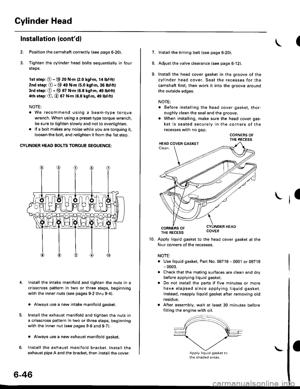
Position the camshaft correctly (see page 6-20).
Tighten the cylinder head bolts sequentially in four
steps.
rsr st.p: O - @ 20 N.m (2.0 kgf.m, 14 lbf'ft|
2nd srep: O - @ 49 N.m (5.0 kgf.m, 36 tbtft)
3rd stop; O - @ 67 N.m {6.8 kgf.m, /r9 lbl'ft}
4th st6p: O, O 67 N.m 16.8 kgf.m, 49 tbf.ftl
NOTE:
. We recommend using a beam-type torque
wrench, When using a preset-type torque wrench.
be sure to tighten slowly and not to overtighten.
. If a bolt makesany noisewhileyou aretorquing it,
loosen the bolt, and retighten it from the 1st step,
CYLINDER HEAD BOLTS TOROUE SEOUENCE:
Install the intake manifold and tighten the nuts in a
crisscross pattern in two or three steps, beginning
with the inner nuts (see pages 9-2 thru 9-4).
. Always use a new intake manifold gasket.
Install the exhaust manifold and tighten the nuts in
a crisscross pattern in two or three steps, beginning
with the inner nut {see pages 9-6 and g-7).
. Always use a new exhaust manifold gasket.
Install the exhaust manifold bracket. lnstall the
exhaust pipe A and the bracket, then install the cover.
4.
6-46
\-
(
7.Installthe timing belt (see page 6-20).
Adjust the valve clearance (see page el2),
Install the head cover gasket in the groove of the
cylinder head cover, Seat the recesses for the
camshaft first, then work it into the groove around
the outside edges.
NOTE:
. Before installing the head cover gasket, thor-
oughly clean the seal and the groove.
. When installing, make sure the head cover gas-
ket is seated securely in the corners of the
recesses wath no gap.
COBNERS OFTHE RECESS
CORNERS OFTHE REcEss covEB
Apply liquid gasket to the head cover gasket at the
four corners of the recesses.
NOTE:
. Use liquid gasket, Pan No. 08718 - 0001 or 08718- 0003.
. Check that the mating surfaces are clean and dry
before applying liquid gasket.
. Do not install the parts if five minutes or more
have elapsed since applying liquid gasket.
Instead, reapply liquid gasket after removing old
residue.
. After assembly, wait at least 30 minutes before
filling the engine with oil.
8.
9.
I
10.