1999 HONDA CIVIC Gearbox oil
[x] Cancel search: Gearbox oilPage 62 of 2189

Unit of length: mm lin)
STANDARD {NEW) SERVICE LIMITMEASUREMENT
Differential
Dtri"*"t"|p'.b"gear
S"t rrg-t" b""il"s
Pinion shaft contact area LD.
Carrier-to pinion clearanceDrive shaft contact area l.D.Carrier to driveshaft clearance
BacklashLD.Pinion gear to-pinion shafl clearance
)uter race clearance
18.010 18.028'0.7091 - 0.7098)
0.023 0.057 (0.0009 - 0.0022) 0.1 (0 004)
26.025 - 26.045 (.0246 1 0254\0.045 0.086 (0.0018 - 0.0034) 0.12(0.005)
0 05 - 0.15 i0 002 0.006)18 042 18.066 {0.7103 0.7" l3)
0.055 - 0.095 (0.0022 - 0.0037) 0.15 {0.006)
0 0.15 (0 - 0.006) Adjlrst
MEASUBEMENT Wire DiaO.D. Free Length I No. of Coils
SpringsPH regulator valve spring 1 2 (0 047)
PH control valve spring 1 7 {0.067)PL regulator valve spring 0 9 (0.035)
PH'PL control valve spring 1 0 (0 039)
crutlh reduc'ns vdrve spnns ] :19 9]:lLLbrication valve spring I b (u ubJr
Shitt valve spring 1 4 (0.055)
Shift control valve spring 1 0 (0.039)
Stan clutch control valve spring 0.4 (0 016)
Pitot regulator valve spring 0.6 (0 024)
Start clutch valve accumulator spring 1 2 \0 O47)
Reverse control valve spring 1 2 (0.047)
Shift inhibitor valve spring 1 3 (0 051)
9.0 {0.354)13.4 (0.528)
1.2lO.2A3\10.0 (0.394)
16.8 (0.661)
13.4 (0.528)
8.2 (0.323)
1 .4 t0.29114.1 (0.161)
5.7 t0.224)8.3 {0.327)9.4 (0.370)
13.2 (0.520)
26.7 (1.051)
39.4 (1.551)
14.6 (0.575)
31.4 (1.236)
44.4 \1.14al51.6 (2.031)
34.1 (1.343)
19.3 (0.760)
12.1 (0.476)
9.5 (0.374)
29.8 (1.173)
31.4 (1.236)
48.3 (1.902)
r0.08.11.28.68.0
13.01.56.85.012.311.010.6
Section 14
SteeringSection 17
M/S: [,4anual steering, P/Sl Power steering*: When using a ne; bett, adjust dellection or tension to new values. Run the engine for 5 minutes then turn it off-
Readjust the deflection or tension to used belt values.
cw
MEASUREMENTSTANDARD {NEWI
Steering wheelPlay at steering wheel circumferenceStarting load at steering wheelcircumferenceN (ksf, lbf)Manual steeringPower steering Engine running
0 - 10 (0 0.4)
15 (1.5,3.3)
29 (3.0,6.6)
GearboxAngle of rack guide screw loosened M/S
from locked position P/S
Preload at pinion gear shaft N m (kglcm, lbfin) M/S
20!5"20'Max0.5 - 1.7 (5 - 17,4.3 - 14.8i
0.6 1.2 (6 - 12, 5.20 - 10.42)
Pump pressure with valve closed(oil temp./speed: 40'C (105"F) min./idleDo not run for more than 5 seconds).kPa (kgtcm?, psi)
6,400 - 7,400 {65 - 75, 920 - 1,070)
Power steeringfluidRecommended power steering fluid
Fluid capacity | {US qt, lmp q0Reservoir
HONDA Power Steering Fluid
0.85 (0.90,0.75) at disassembly0.4 {0.42.0.35}
7.5 11.0 {0.30 - 0.43)with used belt
5.0 7.0 (0.20 0.28) with new belt10.5 - 14.0 10.41 - 0.55) with used belt7.5 10.010.30 0.39) with new belt
390 540 {40 55,88 '120) wrth used bek
340 - 490 (35 - 50, 77 - 110) with used belt
740 880 (75 - 90, 170 - 200) with new belt
640 780 (65 - 80, 143-176)with newbelt
Power steeringbelt*
Deflection with 98 N (10 kgf,22 lbf)
between pulleys '99 modell 81642 Engine Type only
'96 '99 models: Other Engine TYPes
ron.ionffiN (kgf, lbf) '99 model: 81642 Engine Tvpe only'96 -'99 models: Other Engine TYPes'99 modelr 81642 Engine TYPe onlY'96 '99 models: Other Engine TYPes
3-17
Page 72 of 2189
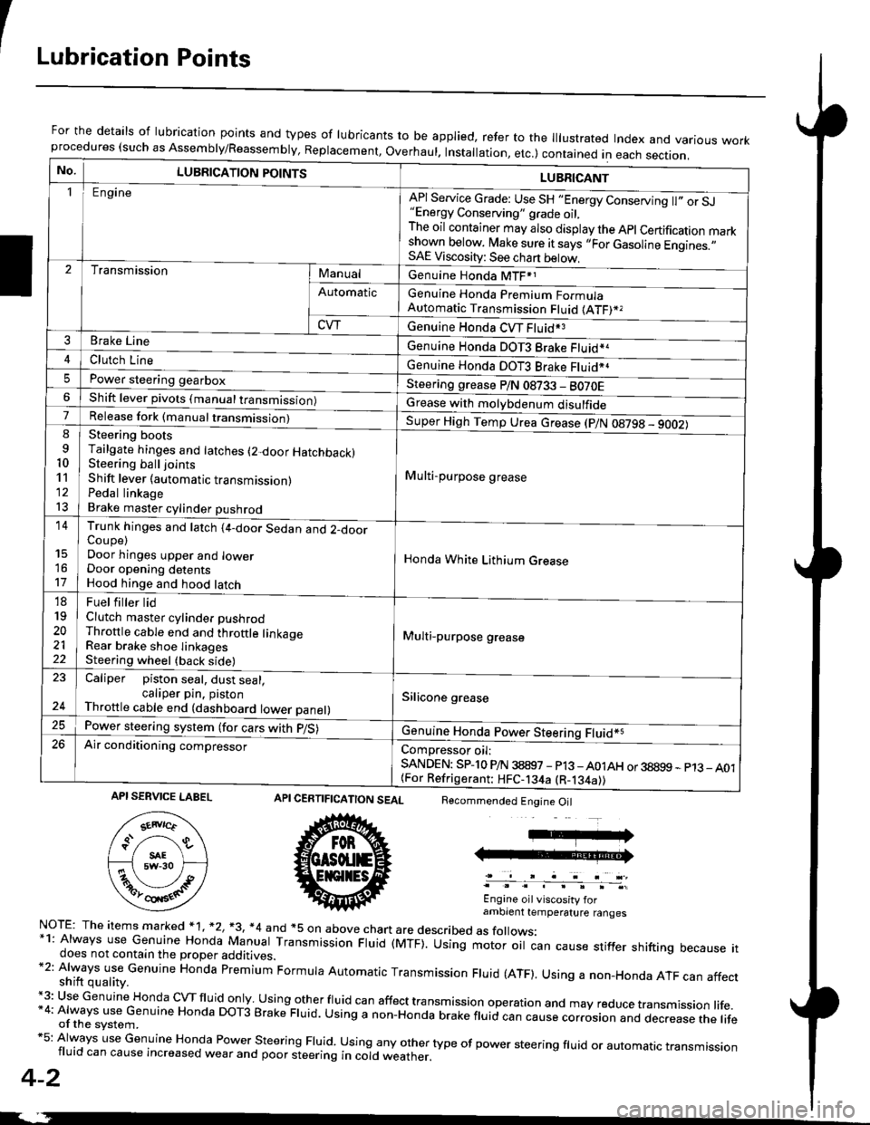
ILubrication Points
For the details of lubrication points and types of lubricants to be applied, refer to the lllustrated Index and various workprocedures (such as Assembly/Reassembly, Replacement, Overhaul. Installation, etc.) contained in each section.
No.LUBRICATION POINTS
Engine
LUBRICANT
"Energy Conserving" grade oil,The oil container may also display the Apl Certification markshown below. Make sure it says ,,For Gasoline Engines.,,SAE Viscosity: See chart below,
I
TransmissionManualGenuine Honda MTF*1
Genuine Honda Premium FormulaAutomatic Transmission Fluid (ATF)*,
Genuine Honda CVT Fluid*3
Genuine Honda DOT3 Brake Fluid*a
Automatic
CVT
3Brake Line
ClL,tci t""e4
I
Genuine Honda DOT3 Brake Fluid*aPower steering gearboxSteering grease P/N 08733 - BO70EShift lever pivots (manual transmission)Grease with molybdenum disulfide7-:ti
9
10'l'l
l3
14
't7
18
19
20
2122
Release fork (manual trancmi
Shift lever (automatic transmission)Pedal linkageBrake master cylinder pushrod
Super High Temp Urea crease (p/N 08798 - 9OO2)
i Multi-purpose grease
I
I
Honda White Lithium Grease
Multi-purpose grease
Silicone grease
@
Trunk hinges and latch (4-door Sedan and 2-doorCoupe)Door hinges upper and lowerDoor opening detentsHood hinge and hood latch-FUet T ter ttd
Clutch master cylinder pushrodThrottle cable end and throttle linkageRear brake shoe linkagesSteering wheel (back side)
23
E-
Caliper piston seal, dust seal,caliper pin. pistonThrottle cable end (dashboard lower panel)
Power steering system (for cars with p/S)
Air conditioning compressorComDressor oil:SANDEN: SPlo P/N 38897 - p13 -A01AH or 38899 - p13_ A01{For Refrigerant: HFC-134a (R-134a))
CERTIFICATION SEAL
ffi
NorE: The items m arked * 1, *2, +3, *4 and +5 on above chan are described as folows:*1: Always use Genuine Honda Manual Transmission Fluid (MTF). Using motor oil can cause stiffer shifting because itdoes not contain the proper additives.*2: Always use Genuine Honda premium Formula Automatic Transmission Fluid (ATF). Using a non-Honda ATF can affectshift quality.+3: Use Genuine Honda cVTfluid only usingotherfluid can affect tra nsmission operation and may reduce transmission life.*4: Always use Genuine Honda DoT3 Brake Fluid. Using a non-Honda brake fluid can cause corrosion and dec.ease the lifeof the svstem.*5: Always use Genuine Honda Power steering Fluid. using any other type of power steering fluid or automatrc transmissionfluid can cause increased wear and poor steering in cold weather.
4-2
Recommended Engine Oil
Engine oil viscosity forambrent temperature ranges
API SERVICE LABEL
Page 1061 of 2189
Steering Gearbox
l.r
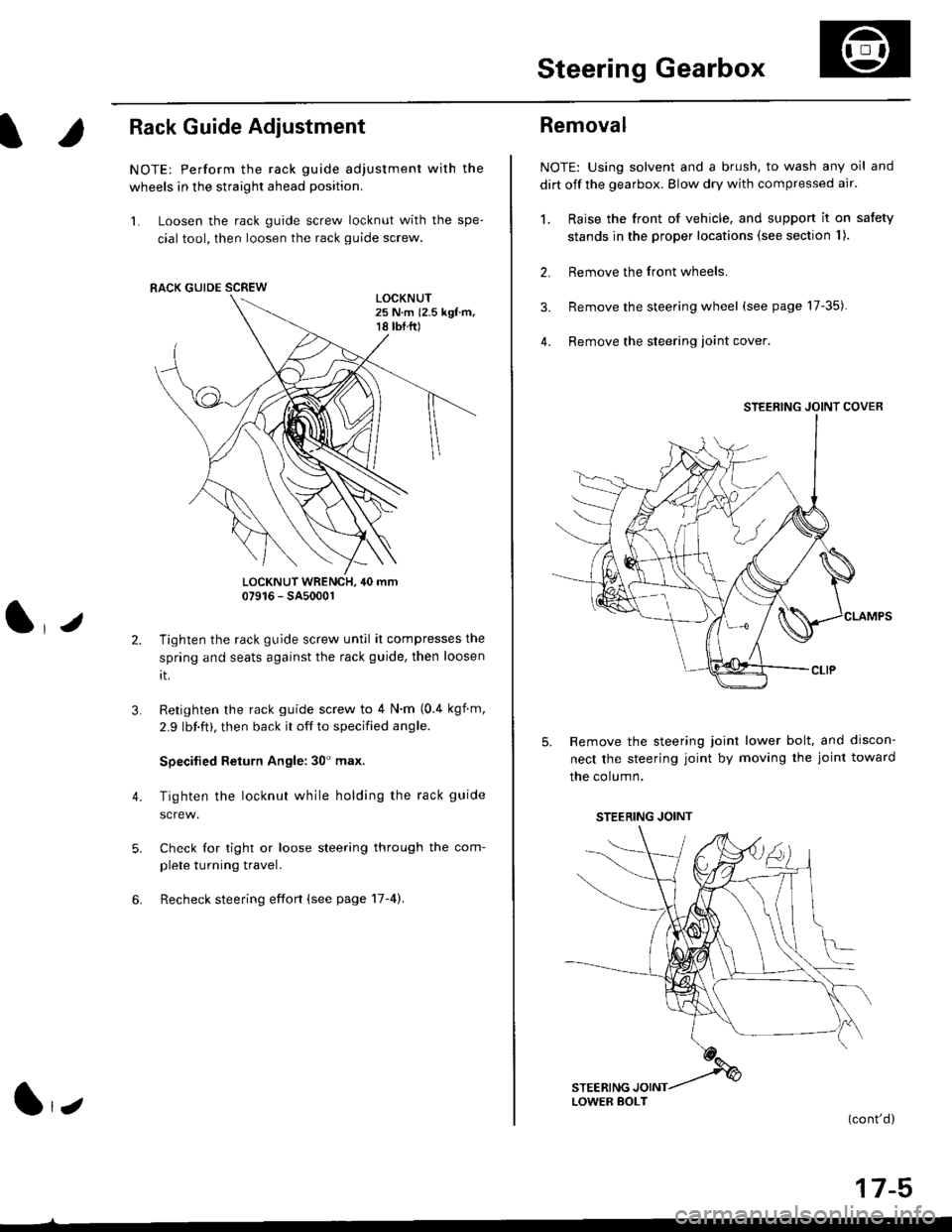
Rack Guide Adjustment
NOTE: Perform the rack guide adjustment with the
wheels in the straight ahead position.
1. Loosen the rack guide screw locknut with the spe-
cial tool, then loosen the rack guide screw.
LOCKNUT WRENCH, 40 mm07916 - SA5000r
Tighten the rack guide screw until it compresses the
spring and seats against the rack guide, then loosen
rt.
Retighten the rack guide screw to 4 N'm (0.4 kgf m,
2.9 lbf.ft), then back it off to specified angle.
Specilied Return Angle: 30' max.
Tighten the locknut while holding the rack guide
Check for tight or loose steering through the com-
plete turning travel.
Recheck steering effort (see page 17-4).
4.
RACK GUIDE SCREW
l,z
Removal
NOTE: Using solvent and a brush, to wash any oil and
dirt off the gearbox. Blow dry with compressed air.
1. Raise the front of vehicle, and support it on satety
stands in the proper locations (see section I ).
2. Remove the front wheels.
3. Remove the steering wheel (see page 17-35).
4. Remove the steering loint cover
Remove the steering joint lower bolt, and discon-
nect the steering joint by moving the joint toward
the column.
(cont'd)
17-5
STEERING JOINT COVER
LOWER BOLT
STEERING JOINT
Page 1074 of 2189
System Description
Steering Pump (cont'dl
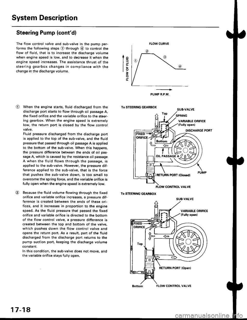
The flow control valve and sub-valve in the pump per-
forms the following steps @ through @ to control the
flow of fluid, that is to increase the discharge volume
when engine speed is low, and to decrease it when the
engine speed increases. The assistance thrust of the
steering gearbox changes in compliance with the
change in the discharge volume.
When the engine starts, fluid discharged from the
discharge port starts to flow through oil passage A,
the fixed orifice and the variable orifice to the steer-
ing gearbox. When the engine speed is extremely
low, the return port is closed by the flow control
Fluid pressure discharged from the discharge port
is applied to the top of the sub-valve, and the fluid
pressure that passed through oil passage A is applied
to the bottom of the sub-valve. When this happens,
the pressure difference between the ends of oil pas-
sage A, which is caused by the resistance oil passage
A when the fluid flows through the passage. is
applied to the sub-valve, However, the pressure dif-
ference applied to the sub-valve. that is the force
that pushes the sub-valve down, is too small to
overcome the spring force, and the variable orifice is
fully open when the engine speed is extremely low.
Because the fluid volume flowing through the fixed
orifice and variable orifice increases, a pressure dif-
terence is created between the ends of these ori-
fices, and it increases in proportion to the engine
speed. As the fluid pressure that passed the fixed
orifice and variable orifice is directed to the bottom
of the flow control valve. a pressure difference is
created between the top and bottom of the valve,
which pushes down the flow control valve and
opens the return port. As a result, pan of the fluid
discharged from the discharge port feturns to the
pump suction port, keeping the discharge volume
constant.
In this condition, the sub-valve does not move. and
the variable orifice stays fully open.
lo
trrtrrlo3
J
o
PUMP R.P.M.
To STEERING GEARBOXSUB.VALVE
To STEEnING GEARBOX
FLOW CURVE
!rs+/f/ffih\
o,,-i^"l^tKzYt)91y ul3Yl
FLOW CONTNOL VALVE
su8-vALvE
ORIFICE
ToP
17-18
FLOW CONTROL VALVE
Page 1075 of 2189
t
To STEERING GEARBOX
To STEERING GEAREOx
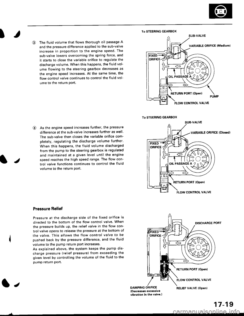
@ The fluid volume that flows thorough oil passage A
and the pressure djfference applied to the sub-valve
increase in proportion to the engine speed. The
sub-valve lowers overcoming the spring force, and
it stans to close the variable orifice to regulate the
discharge volume, When this happens, the fluid vol-
ume flowing to the steering gearbox decreases as
the engine speed increases. At the same time, the
flow control valve continues to control the fluid vol-
ume to the return Port,
@ As the engine speed increases funher, the pressure
difference at the sub-valve increases further as well.
The sub-valve then closes the variable orifice com-
pletely, regulating the discharge volume further.
When this happens, the fluid volume discharged
from the pump to the steering gearbox is regulated
and maintained at a given level until the engine
speed reaches the high speed range The flow con-
trol valve functions continues to control the fluid
volume to the return Port.
Pressure Relief
Pressure at the discharge side of the fixed orifice is
directed to the bottom of the flow control valve. When
the pressure builds up, the relief valve in the flow con-
trol valve opens to release the pressure at the bottom of
the valve. This allows the flow control valve to be
pushed back by the pressure difference, and the fluid
volume to the pump return port increases.
As explained above. the system keeps the pump dis-
charge pressure (relief pressure) from exceeding the
given level by controlling the volume of the fluid to the
pump relurn pon,
1.,DAMPING ORIFICE{Docreases excessiv€vibration in the valv6.)
17-19
)
RELIEF VALVE {Opan)
SUB.VALVE
FLOW CONTROL VALVE
/F ft>..\
'-€/K\A/A
o'.'to"5lo'#2"n af11\D7
FLOW CONTROL VALVE
Page 1081 of 2189
/
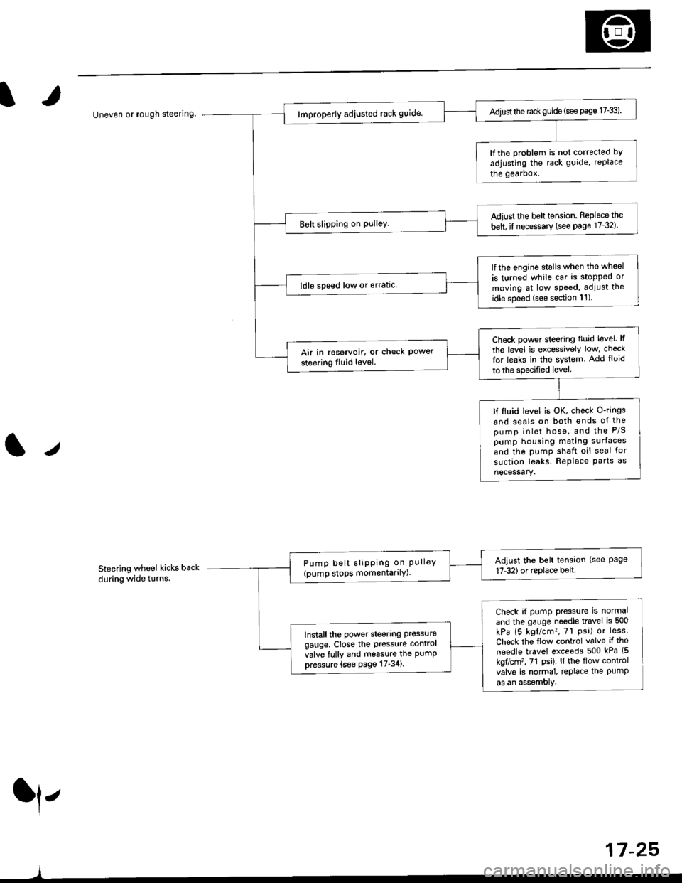
Uneven or rough steering
Steering wheel kicks back
during wide t!rns.
ll,
)
Adjust the rac* guide (see page 17-3).
lf the problem is not corrected bY
adjusting the rack guide, replace
the gearbox.
Adiust the belt tension. Feplace the
belt, il necessary (see Page 17 32).
lfthe engine stalls when the wheel
is turned while car is stopped or
moving at low speed, adjust the
idle spe€d (see section 11)
ldle speed low or erratic.
Check power sleering fluid level lf
the level is excessively low, check
lor leaks in the system. Add lluid
to the specified level.
Air in reservoir, or check Powersteering Iluid level.
lf ltuid level is OK, check O-rings
and seals on both ends of thepump inlet hose, and the P/Spump housing mating surfaces
and the pumP shaft oil seal for
suction leaks. RePlace Parts as
nocessary.
Adjust the belt tension (see Page17 32)or replace belt.Pump belt sliPPing on PLrlleY(pump stops momentarilY)
Check if pump press{rre is normal
and the gauge needle travel is 500
kPa (5 kgl/cm?, 7l Psi) or less.
Chock the flow control valve if the
needle travel exceeds 500 kPa (5
kgflcm'�, 71 Psi). l{ the flow control
valve is normal, replace the PumPas an assemoly.
Install the power steering pressure
gauge, Close the Pressure contrcl
valve fully and m6ssure the PumPpressure {s€e page 17-34}.
17 -25,
Page 1084 of 2189
Troubleshooting
Fluid Leaks
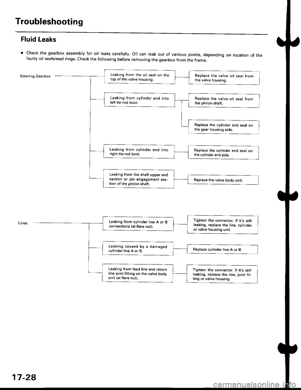
Check the gearbox assembly for oil leaks carefully. Oil can leak out of various points. depending on location of thefaulty oil seals/seal rings. Check the following before removing the gearbox from the frame_
Steering GearboxLeaking from the oil seal on thetop of the valve housing.Replace the valve oil seal fromthe valve housing.
Leaking from cylinder end intoleft tie rod boot.Replace the valve oil seal tromthe pinion shaft.
Replace the cylinder end seal onthe gear housing side.
Leaking lrom cylinder end intoright tie-rod boot.Replace the cylinder end seal onthe cylinder end side.
Leaking lrom the shaft upper endsectron or pin engagement sec,tion ol the pinion shaft.Replace the valve body unit.
Tighten the connector. lf it's stillleakinO, replace the Iine, cylinderor valve housing unit.
Leaking from cylinder line A or Bconnections {at tlare nut}.
Leaking caused by a damagedcylinde.line A or B.Replace cvljnder line A or B.
Leaking from feed line and returnline ioint fitting on the valve bodyunit (at flare nut).
Tighten the connector. ll it's stillleaking, replace the line,,oint fit,ting or valv6 housing.
17-2a
Page 1103 of 2189
Steering Gearbox
)
Removal
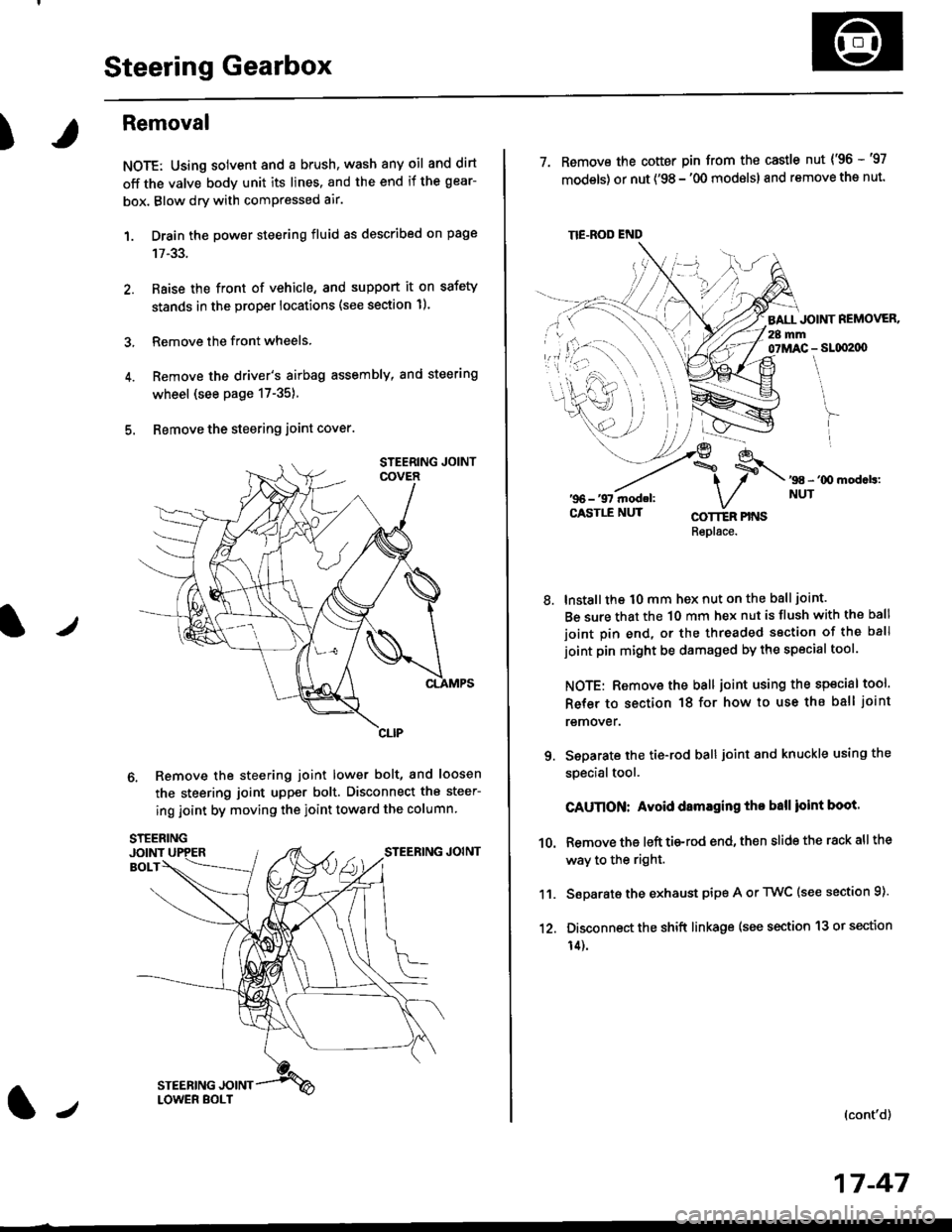
NOTE: Using solvent and a brush, wash any oil and dirt
off the valve body unit its lines. and the end if the gear-
box. Blow dry with comPressed air.
1. Drain the power steering fluid as described on page
2. Raise the front of vehicle, and support it on safety
stands in the proper locations (see section 11.
3, Remove the front wheels.
4. Remove the driver's airbag assembly, and steering
wheel (see page 17-35)
5. Bemove the steering joint cover.
6. Remove the steering joint lower bolt, and loosen
the steering joint upper bolt. Disconnect the steer-
ing joint by moving the ioint toward the column
tJ
17-47
TIE.ROD END
7. Remove the cotter pin from the castle nut {'96 -'97
models) or nut ('98 - '00 modslsl and remove the nut.
BALL JOINT REMOVER.28 mm07MAC - SLqI2|X)
'98 - '00 mod.b:NUT
8.
COTTER PINSRepl6ce.
lnstall the t0 mm hex nut on the ball joint.
Be sure that the 10 mm hex nut is flush with the ball
joint pin end, or the threaded section of the ball
joint pin might be damaged by the special tool.
NOTE: Remove the ball joint using the special tool.
Refer to section 18 for how to use ths ball joint
remover.
Seoarate the tie-rod ball joint and knuckle using the
specialtool.
CAUnON: Avoid damaging tho ball ioint boot.
Remove the left tie-rod end, then slide the rack all the
way to the right.
Separate the exhaust pipe A or TWC (see section 9).
Disconnect the shift linkage (see section 13 or section
14).
(cont'd)
9.
10.
11.
12.