1999 HONDA CIVIC Shift
[x] Cancel search: ShiftPage 867 of 2189
Shift Cable
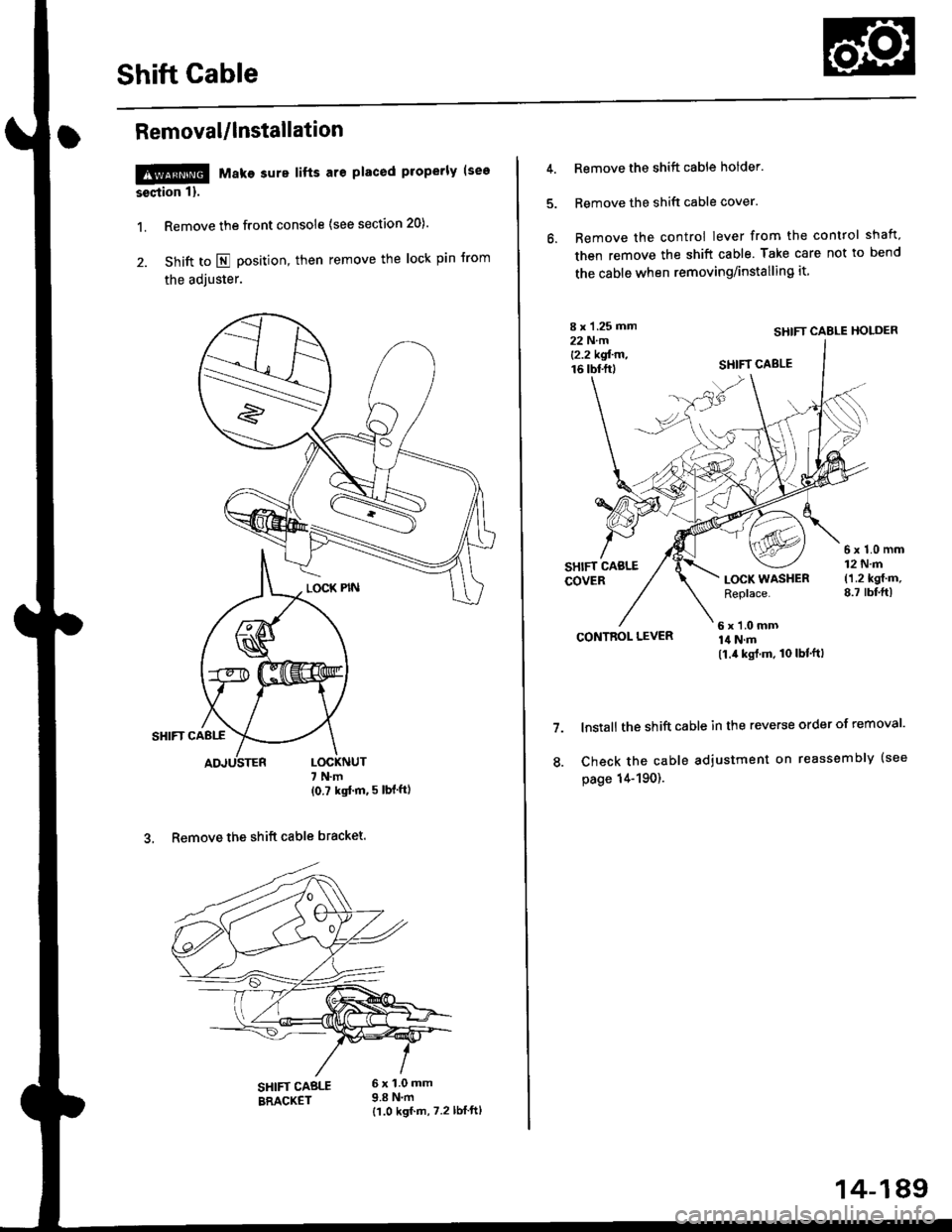
Removal/lnstallation
!@@ Make sure lifts are placed properly (see
seqtion 1).
1. Remove the front console (see section 20).
2. Shift to E position, then remove the lock pin Jrom
the adjuster.
SHIFT CABI.f
7 N.m(07kst'm,5lbl'ftl
3, Remove the shift cable bracket.
SHIFT CABLEBRACKET
6x1.0mm9.8 N.m{1.0 kgf m, 7.2
4. Remove the shift cable holder.
5. Bemove the shift cable cover.
6. Remove the control Iever from the control shaft,
then remove the shift cable. Take care not to bend
the cable when removing/installing it
I x '1.25 mm22 N.m12.2 kgl'm�.16 tbl.ftl
SHIFT CABLE HOLDER
SHIFT CABLE
LOCK WASHERReplace.
6x1.0mm12 N.m('1.2 ksf.m,8.7 rbtftl
CONTBOL LEVER6 x 'l.0 mm14 N.m
7.
(!.il kgt.m. 10lbl.ftl
lnstall the shift cable in the reverse order of removal'
Check the cable adjustment on reassembly (see
page 14-190).
14-189
Page 868 of 2189
Shift Cable
Adjustment
@ Make sure lifts are ptaced properly (see
section 1).
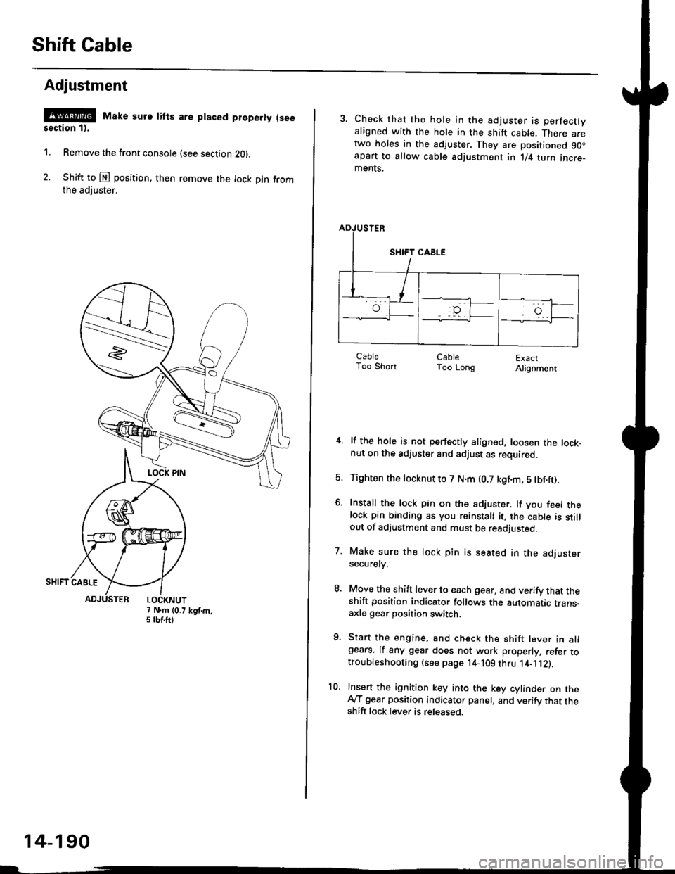
1. Remove the front console (see section Z0l.
2. Shift to @ position. then remove the lock pin fromthe adiuster.
7 N.m (0.75 tbtftlkgtm.
14-190
3. Check that the hole in the adjuster is perfectlyaligned with the hole in the shift cable. There aretwo holes in the adjuster. They are positioned 90.apart to allow cable adjustment in 1/4 turn incre-ments.
ExactAlignment
4. lf the hole is not perfectly aligned, loosen the lock-nut on the adjuster and adjust as required.
5. Tighten the tocknut to 7 N.m (0.7 kgf.m, 5 tbf.ft).
6. Install the lock pin on the adjuster. lf you feel thelock pin binding as you reinstall it, the cable is stillout of adjustment and must be readjusted.
7. Make sure the lock pin is seated in the adjustersecuretv.
8. Move the shift lever to each gear, and verify that theshift position indicator follows the automatic trans-axle gear position switch.
9. Start the engine, and check the shift lever in allgears. lf any gear does not work properly, refer totroubleshooting (see page 14-109 thru 1'4-'112).
10. Insert the ignition key into the key cylinder on theAy'T gear position indicator panel, and verify that theshift lock lever is released.
CableToo ShortCableToo Long
Page 869 of 2189
Shift Lever
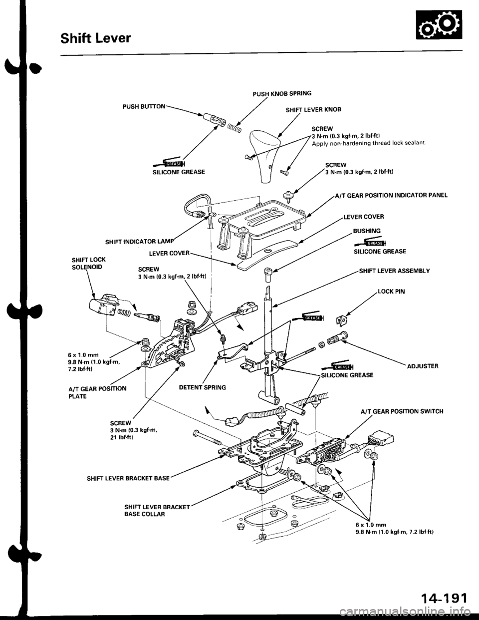
PUSH KNOB SPRING
SILICONE GREASE
SCBEWN.m {0.3 kgtm.2 lbf ft)
Apply non-hardening thread lock sealant
SCREW3 N.m {0.3 kgif m,2 lblft)
GEAR POSITION INDICATOR PANEL
COVER
SHIFT LEVER ASSEMBLY
SHIFT INDICATOR
BUSHING
-61SILICONE GREASELEVERSHIFT LOCK
SCREW3 N.m {0.3
g
6x1.0mm9.8 N.m {1.0 kgf.m,7.2 tbt.ft)
A/T GEAR POSITION
PLATE
SHIFT LEVER BRACKET BASE
SHIFT LEVER
2/""*"
,.@* _.\__r.\
-Rt \ooru.r.,
A/T GEAR POSITION SWITCH
6x1.0mm9.8 N.m 11.0 kgf.m.7.2lbf.ft)
BASE COLLAA
14-191
Page 870 of 2189

Shift Indicator PanelATF Cooler Hoses
Adiustment
'1.Check that the index mark on the indicator alionswith the N mark on the shift indicator panel whenthe transmission is in NEUTRAL.
3 N.m {0.3 kgf.m, 2lbt.ftl
lf not aligned. remove the front console {see section20t.
Remove the shift indicator panel mounting screwsand adjust by moving the panel,
NOTE: Whenever the shift indicator panel is removed,reinstallthe panel as described above,
INDEX MARK
L
14-192
Connection
1. Connect the ATF cooler hoses to the ATF cooler linesand ATF cooler, and secure them with the clips asshown.
TRANSMISSION CLIP
Page 871 of 2189

Continuously Variable Transmission (CVTI
Special Tools ................ 14-194
Description .................... 14-195
Clutches/Reverse Brake/Planetary
Gear/Pulleys .......... 14-198
power Flow ..............,..... 14-200
Electronic Control SYstem(,96 - 98 Modets) ......14-203
Electronic Control System
('99 - oo Models) " 14-205
Hydraulic Control '....... 14-208
Hydraulic Flow .'..-.....'... '14-212
Park Mechanism .....-...'.' 14-222
Eleqtrical Systom
Component Locations'96 - 98 Models """"""' 14-224,99 - 00 Modets ............. 14-225
TCM Circuit Diagram ('96 - 98 Models) ............. 14-226
TCM Terminal Voltage/Measuring Condiiions ('96 - 98 Models) '.... 14-228
PcM Circuit Oiaqram{A/T Control System: '99 - 00 Models} ...--.... 14-230
PCM Terminal Voltage/Measuring Conditions('99 - 00 Models)
A/4 Control System .'.'...14-232
Troubleshooting Procedures ... . .... .....',........."' '14-234
Symptom-to-ComPonent Chart
Electrical System - '96 - 98 Models ......'..... '14-234
Electrical System -'99 - 00 Models ..'....-..-. '11-210
Electrical Troubleshooting
Troubleshooting Flowcharts('96 - 98 Models) """'11-242
Troubleshooting Flowchart
('99 - 0O Modets) ...... 14-265
Linear Solenoids/lnhibitor Solenoid
Test ......................... . ...... 14-29f
Drive Pulley/Driven Pulley/Secondary Gear
Shaft Speed Sensors
Replacement .........'...... .14-292
Start Clutch Control
Start Clutch Calibration Procedure ....... ....,. 14-293
Hydraulic SYstem
Symptom-to-ComPonent Chart
Hydraulic System '.'.......14-294
Road Test ............................ 14-296
Stall Speed
Test......................... ...... 14-294
Fluid Level
Checking/Changing ....... 14-299
Pressure Testing ................. 14-300
Lower Valve BodY AssemblY
Replacement ..........,... 14-302
ATF Filter
Removal/lnstallation ..... 14-303
Transmission
Transmission
Removal ........... . 14-304
lllustrated Index
Transmission/Lower Valve BodY
Assembly ................. 14-308
Transmission Housing/Flywheel Housing ... 14-310
End Cover/f ntermediate Housing ..........'.'.... 14-312
Transmission Housing/Lower Valve Body Assembly
Removal ..........'.... .. " 14-314
Transmission Housing/Flywhesl Housing
Removal ................. ........ 1+316
End Cover/lntermediate Housing
14-318Removal .........,...............
Manual Valve Body
Disassembly/lnspection/Reassemblv .'.'.'..... 1 4-320
Forward Clutch
lltustrated Index ........................................ 14-321
Disassemblv .................. 14-322
Reassemblv , ,, . ',','......14-324
Secondary Gear Shaft
25 x 35 mm Thrust Shim Selection ..'.'....-... 14-324
Differential
lllustrated lndex ...,.....................,.,...-.-.-...'... 14-329
Backlash Inspection .-....14-329
Bearing Replacement ......'........'....'... ....'... 14-330
Differential Carrier Replacement ........'........ 14-330
Oil Seal Removal ........... 14-331
Oil Seal Installation/Side Clearance ....... . . 14-331
Flywheel Housing Input Shaft Oil Seal
Replacement .....,.... ...'.'.. 14-333
Transmission Housing Bearings
Driven Pulley Shaft Bearing
Replacenient ...................'. . ...................'.. 14-334
Secondary Gear Shaft Bearing
Reolacbment ...................... . .......... . ........ 14-335
Flywheel Housing Beating
Secondary Gear Shaft BearingReo1acement..................,........................... 14-335
Ring Gear Bearing
Replacement......... ........ 14-336
Control Shaft Assembly
Removal/lnstallation ....................'........... 14-336
Transmission
Reassembly .................. 14-338
Flywheel/Drive Plate .. . ...... . ...... ... . ....-.....'.'...14-341
Transmission
lnstalation ..................... 14-348
Cooler Flushing .'......... 14-352
shift cable
Removal/lnstallation....'........." """ 14-354
Adjustment .......'........ 14-355
Shift Lever ........................,. 14'356
Shift Indicator Panel
Adjustment ................ 14-357
ATF Cooler/Hoses
lnsta llation ......,,...... .... 14-357
Page 873 of 2189

Description
The Continuously Variable Transmission (CVT) is an electronically controlled automatic transmission with drive and driv
en Oullevs, and a steel belt. The CVT provides non stage speeds forward and one reverse. The entire unit is positioned in
line with the engine.
Transmission
Around the outside of the flywheel is a ring gear which meshes with the starter pinion when the engine is being staned.
The transmission has four parallel shafts: the input shaft, the drive pulley shaft. the driven pulley shaft, and the secondary
gear shaft. The input shaft is in line with the engine crankshaft. The drive pulley shaft and the driven pulley shaft consist of
movable and fixed face pulleys. Both pulleys are linked by the steel belt.
The input shaft includes the sun gear. The drive pulley shaft includes the forward clutch which mounts the carrier assem-
bly on the forward clutch drum. The carrier assembly includes the pinion gears which mesh with the sun gear and the ring
gear. The ring gear has a hub-mounted reverse brake disc.
The driven pulley shaft includes the start clutch and the secondary drive gear which is integral with the park gear' The sec-
ondary gear shaft is positioned between the secondary drive gear and the final driven gear. The secondary gear shaft
includes the secondary driven gear which serves to change the rotation direction. because the drive pulley shaft and the
driven oullev shaft rotate the same direction. When certain combinations of planetary gears in the transmission are
engaged by the clutches and the reverse brake, power is transmitted from the drive pulley shaft to the driven pulley shaft
to provide E, E, E, and El.
Electronic Control'96 - 98 Models:
The electronic control system consists of the Transmission Control Module (TCM), sensors, three linear solenoids, and a
inhibitor solenoid. Shifting is electronically controlled under all conditions'
The TCM is located below the dashboard, behind the kick panel on the driver's side.'99 - 00 Models:
The electronic control svstem consists of a Powertrain Control Module (PCM), sensors, three linear solenoids and an
inhibitor solenoid. Shifting is electronically controlled under all conditions. A Grade Logic Control System to control shift-
ing in E position while the vehicle is ascending or descending a slope.
The PCM is located below the dashboard, under the kick panel on the passenger's side.
Hydraulic Control
The lower valve body assembly includes the main valve body, the Pressure Low (PL) reguiator valve body, the shift valve
body, the start clutch control valve body, and the secondary valve body. They are positioned on the lower part of the
transmission housing.
The main valve body contains the Pressure High (PH) control valve, the lubrication valve, and the pitot regulator valve.
The secondary valve body contains the PH regulator valve, the clutch reducing valve, the start clutch valve accumulator,
and the shift inhibitor valve. The PL regulator valve body contains the PL regulator valve and the PH-PL control valve
which is ioined to the PH,PL control linear solenoid. The inhibitor solenoid valve is bolted on the PL regulator valve body.
The shift valve body contains the shift valve and the shift control valve. which is joined to the shift control linear solenoid.
The start clutch control valve body contains the start clutch control valve, which is joined to the start clutch control linear
solenoid. The linear solenoids and the inhibitor solenoid are controlled by the TCM or PCM. The manual valve body which
contains the manual valve and the reverse inhibitor valve, is bolted on the intermediate housing.
The ATF pump assembly is located on the transmission housing, and is linked with the input shaft by the sprockets and
the sprocket chain. The pulleys and the clutch receive fluid from their respective feed pipes, and the reverse brake receives
fluid from internal hydraulic circuit.
Shift Control Mechanism
Input from various sensors located throughout the vehicle determines which linear solenoid the TCM or PCM will activate.
Activating the shift control linear solenoid changes the shift control valve pressure, causing the shift valve to move. This
pressurizes the drive pulley pressure to the drive pulley and the driven pulley pressure to the driven pulley and changes
their effective pulley ratio. Activating the start clutch control linear solenoid moves the start clutch control valve. The start
clutch control valve uncovers the port, providing pressure to the start clutch to engage it(cont'd)
14-195
,!
Page 874 of 2189
Description
(cont'd)
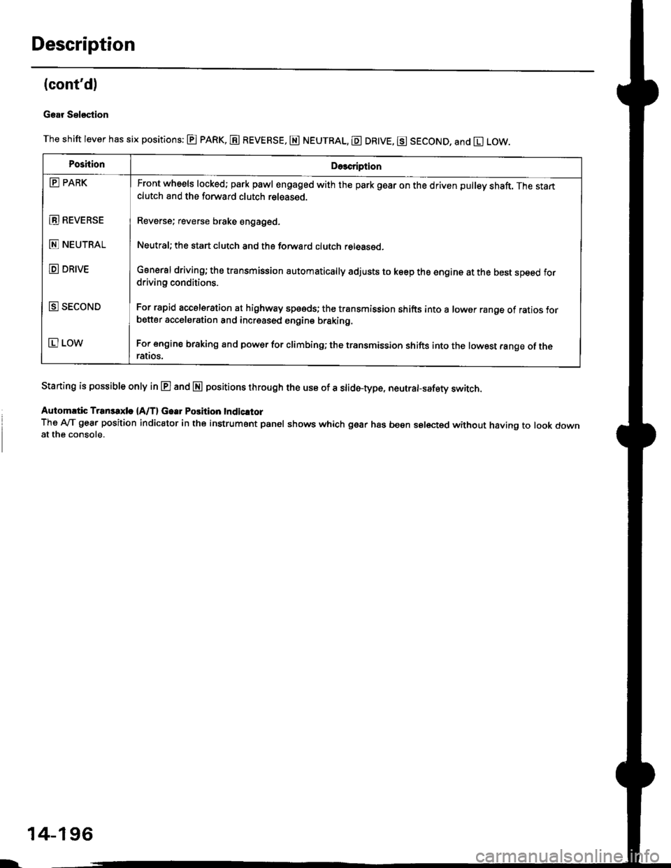
Gear Sel€stion
The shift lever has six positions: @ pARK, E REVERSE, E NEUTRAL, E DR|VE, g SECOND, and El LOW.
Staning is possible only in E and E positions through the use of a slid6-type, neutrafsafety switch.
Automrtic Transaxle {A/T} Gear Position Indicltor
The A-lT gear position indicator in the instrument panel shows which gear has been selected without having to look downat the console.
PoshionDe3cription
E PARK
E REVEBSE
E NEUTRAL
D DRIVE
E SECOND
E LOW
Front wheels locked; park pawl engaged with the park gear on the driven pulley shaft. The startclutch and the forward clutch released.
Reverse; reverse brake engaged.
Neutral; the start clutch and the forward clutch released.
General driving; the transmission automatically adjusts to keep the engine at the best speed fordriving conditions.
For rapid accelsration at highway speeds; the transmission shifts into a lower range of ratios forbetter acceleration and increased engine braking.
For engine braking and power for climbinO; the transmission shifts into the lowest range of theralros.
l-
14-196
Page 881 of 2189
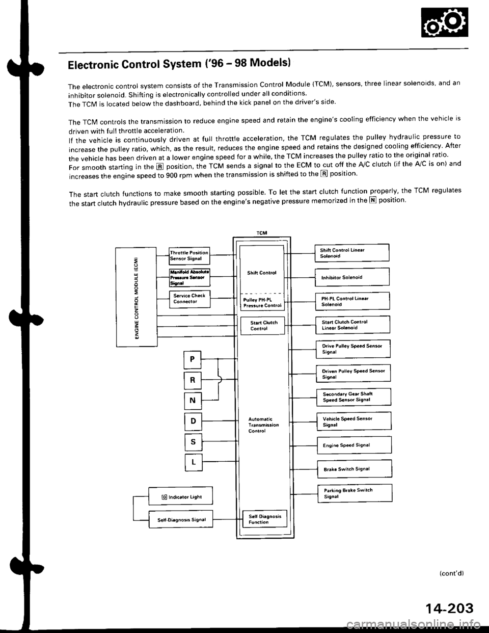
Electronic Control System ('96 - 98 Modelsl
The electronic control system consists of the Transmission control Module (TcM), sensors, three linear solenoids, and an
inhibitor solenoid. Shifting is electronically controlled under all conditions
The TCIM is located below the dashboard, behind the kick panel on the driver's side'
The TcN4 controls the transmission to reduce engine speed and retain the engine's cooling efficiency when the vehicle is
driven with Iull throttle acceleration
lf the vehicle is continuously driven at full throttle acceleration, the TCM regulates the pulley hydraulic pressure to
increase the pulley ratio, which, as the result. reduces the engine speed and retains the designed cooling efficiency After
the vehicle has been driven at a lower engine speed for a while, the TCM increases the pulley ratio to the original ratio.
For smooth starting in the E position, the TcM sends a signal to the EcM to cut off the rvc clutch {if the A!/c is on) and
increases the engine speed to 900 rpm when the transmission is shifted to the E position'
The start clutch functions to make smooth starting possible. To let the start clutch function properly. the TCM regulates
the start clutch hydraulic pressure based on the entine's negative pressure memorized in the E position'
:
:
z
z
z
S*ond.ry G..r Sh:ft
(cont'd)
14-203