Page 766 of 2189
![HONDA CIVIC 1999 6.G Workshop Manual Electrical Troubleshooting (gg - 00 Models)
Troubleshooting Flowchart - A/T Gear position Switch Open {cont,d)
PCM CONNECTORS
B l2sPlD {16P)
124156I
91011)./t5l/11189112
zo ztzzl l//l hsr),41
f ]_c;l HONDA CIVIC 1999 6.G Workshop Manual Electrical Troubleshooting (gg - 00 Models)
Troubleshooting Flowchart - A/T Gear position Switch Open {cont,d)
PCM CONNECTORS
B l2sPlD {16P)
124156I
91011)./t5l/11189112
zo ztzzl l//l hsr),41
f ]_c;l](/manual-img/13/6068/w960_6068-765.png)
Electrical Troubleshooting ('gg - 00 Models)
Troubleshooting Flowchart - A/T Gear position Switch Open {cont,d)
PCM CONNECTORS
B l2sPlD {16P)
124156I
91011)./t5l/11189112
zo ztzzl l//l hsr),41
f ]_c;l
j r-cz tgaNlelxr -ATP D4
Wire side of lemale terminals
(YEL}LGl {BRN/BI.KI
I.G1 IERN/BLKI
B (25P1
LGl IBRN/BLKI
D {16P}
From page 14-87
Moalure ATP 04 Vohago:1. Shift to pll position.2. Measure the voltage betweenthe Dg and 820 or 822 terminals.
Repair opon in the wire betweonthe lrg terminal and the A/T goatposhion switch.
Measure ATP D3 Vohage:1. Shift to l& position.2. Measure the voltage betweenthe D8 and 820 or 822 termi-nats.
Reprir opcn in the wirc b?twoenthe D8 terminrl and tho A/T goarDosition twitch.
Mersurc ATP 2 Voltage:1. Shift to E position.2. Measure the voltage betweenthe Dl4 and 820 or 822 termi-nals,
Reprir opon in the wire betweontho Dl4 te.minal rnd the A/Tgo.r position switch.
Ch6ck tor loose terminal tit in thePCM connectors. ll necossery,subslitute . known-good pCM
and recheck.
LG2IBRN/BLKI
I25l l6l/8
91011)/Itsln78912
ATP 2 IBLUI
t..
14-88
Page 767 of 2189

Troubleshooting Flowchart - Shift Control Solenoid Valve A
NOTE: Record allJreeze data before you troubleshoot.
Possible Cru3.
' Disconnectod 3hift control
solonoid valva A/B a33emblY
connactot. Short or opon in shift cont.ol
solonoid valvo A wits. Faulty shift control .olenoid
. op.n in vB SOL wi.e
To page 14-90
PCM CONNECTOBS
LG1{BRN/BLK} LG2IBRN/BLKI
Wire side of female terminals
LGl IBRN/BI-K)LG2IBBN/BLK)
. OBD ll Scan Tool indic.ts6 Code
Pot53.. Solt-diagno.is E indicrtot light
blinks seven time6.
Chock tor a Short to Power:
1. Turn the ignition switch OFF.
2. Disconnect the g (25P) and D(16P) conneclors from the
PCM,3. Turn the ignirion switch ON (ll)
,1. Measure the voltage between
the D7 and 820 or 822 termi
nals,
Rcpair short to powet in the wile
b€t^reen tho D7 termin.l .nd the
shift control aolonoid valve A.
Mee3ur. Shift Control Solonoid
Valve A Roaisttnce:1. Turn the ignition switch OFF.
2. Measure the resistance
between the D7 and 820 or
822 terminals.
ls the resistance 12 - 25 O?
Me.3uro vB SOL Voh.ge:1. Turn the ignition switch ON (ll).
2. Measure the voltage betweenthe D5 and 820 or 822 termi-
nals.
Check tor blown No. 15 17.5 A)
fuse in tho underdaah fula/rol.Ybox. ll the tusr is OK, .epair oPenin th. wiio betwe.n the D5 ter'min.l and th. underdssh tuso/relav box.
ls there baftery voltage?
Check for loose t6tminalfit in th€
PCM connoctors. It necessary,substitute e known-good PCMand rechock.
I t25Pt ll D {16P)
B rzsPt o trQil
(cont'd)
14-89
Page 768 of 2189

Electrical Troubleshooting ('gg - 00 Models)
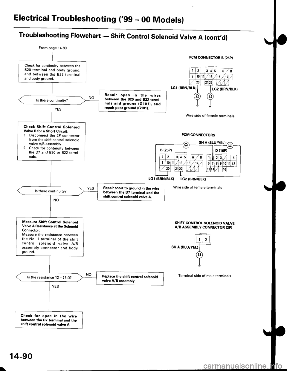
Troubleshooting Flowchart - Shift Control Solenoid Valve A (cont,O)
PCM CONNECTOR B {25P}
LGl (BRN/BLKI
Wire side of female terminals
rcM CONNECTORS
LGl {BBN/BLKI LG2 (BRN/BLKI
Wire side of female terminals
SHIFT CONTROL SO|'INOID VALVEA/B ASSEMBLY CONNECTOR I2PI
SH A {BLU/YELI
From page 14-89
Check lor continuity between the820 terminal and body ground,and between the 822 terminaland body ground.
Repair open in ihe wiresbetween th€ 820 and 822 termi-nals end ground {G10ll. andrepa,r poor ground {G101}.
Check Shitt Control SolenoidValve B for a Short Circuit:1. Disconnect the 2P connectorfrom the shilt control solenoidvalve A,/B assembly.2. Check lor continuity betweenthe D7 and 820 or 822 termi,nals.
R€pair short to ground in the wiiebartwe€n the D7 te.minal and theshift control solonoid valve A.
ls there continuity?
Meesuro Shift Control SolenoidValve A RGistance at the SolenoidConnector:Measure the resistance betweenthe No. 1 terminal of the shiftcontro I solenoid valve A/Bassembty connector and bodygrounct,
Repl.ce tho shift control solenoidvalve A/B rss€mblv.ls the resistance 12 25 O?
Check for open in the wirebetween the D7 termindl and theshift control 3olonoid valve A.
B t25Pt llD t16Pt
\
14-90
Page 769 of 2189

Troubleshooting Flowchart - Shift ControtSolenoid Valve B
NOTE: Record all freeze data before you troubleshoot.
Possiblg Cause
. Disconnectgd ihilt control
solenoid valve A/B conneciotr Short or oDen in shift conlrol
3olgnoid vrlve B wito. Faulty 3hift control solenoid
velve B. Op€n in VB SOL wirercM CONNECTORS
LGlIBRN/BLKI LG2IBRN/BLK)
Wire side of {emale terminals
LGi (BRi|/BLKILG2 IBRN/8LK)
To page 14-92
(cont'd)
14-91
. OBD ll Scan Tool indic.l6 Code
P0758.' Self-diagnosb El indicator light
blinks eighl tim6.
Check tor a Shortto Power:
1. Turn the ignition switch OFF
2. Disconnect the B (25P) and D(16P) connectors from the
PCM.3. Turn the ignition switch ON (lli.
4. Measure the voltage between
the D2 and 820 or 822 termi
nals,
Repaft 3hon to Powor in the wir€
b€tirvoon the D2 termin.l and the
3hift control solenoid valve B.
M€asure Shift Control SolenoidValve B R6isttnce:1. Turn the ignition switch OFF
2. Measure the resistance
between the D2 and 820 or
822 terminals.
ls the resistance 12 - 25 O?
Me.sure VB SOL Vohage:1. Turn the ignition switch ON (ll).
2. Measure the voltage betweenthe D5 and 820 or 822 termi'
nars.
Check lol blown No 15 {7.5 Al
fuse in the under-d.sh luae/rolav
box. ll the fuse is OK, repair open
in ihe wire between tho D5 ter-
minal and the under'dash fus€/relav box.
ls there battery voltage?
Check for loo3e terminal fit in the
PCM connectols. lf necossarY,
substitute a known_good PCM
and rocheck,
B (25Pt - I lD {16P)
B {25P1 D (t6Pl
Page 770 of 2189

Electrical Troubleshoot:ng ('gg - 00 Models)
Troubleshooting Flowchart - Shift Control Solenoid Valve B (cont,dl
PCM CONNECTOR A {25PI
LGl (BRN/BLK)
IBRN/BLKI LG2IBRN/BLK)
Wire side of temale terminals
Wire sid€ ot female terminals
FCM CONNECTORS
SHIFT @NTROL SOENOID VALVEA/A ASSEMBLY CONNECTOR (2PI
.-_
1)2-.T-
I sn e tcanlwxrt
(o
YI
Terminal side oI male terminals
Check for continuity between the820 terminal and body ground,and between the 822 terminaland body ground.
Ropair opan in the wirgsb.twocn the 820 rnd 822 te.mi,n.ls and ground lG10t), and..p.ir poor ground lG10t).
Check Shift Control Sol.noidVrlve B tor a Short Ci.cuit:1. Disconnect the 2P connectorfrom the shift control solenoidvalve A/B assembly.2. Check for continuity betweenthe D2 and 820 or 822 termi-nals.
Repair 3hort to ground in tho wirebotw.en tha 02 torminsl and theshift com.ol rolonoid v.lv. B.
Meaiuro Shift Cont.ol SolonoidVrlve B Raailtrnca at the SolonoidConn€c,toa:Messure the r€sistance belweenthe No. 2 terminal of the 6hiftcontrol solenoid valve A/Bassembly connector and bodyground.
R.pl.co th. 3hift control lolenoidv!lv. A/8.lsombly.ls the resistance 12 - 25 O?
Chack for open in the wi.ebetwoon th€ D2 termin.l and the3hift control lolanoid valv6 8.
B (25P1 - llDt
From page'14-91
SH B (GRN/WHTI
\
14-92
Page 778 of 2189

Electrical Troubleshooting ('99 - 00 Modelsl
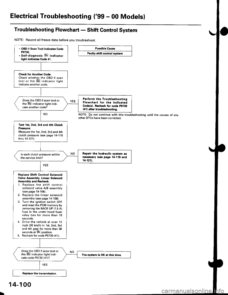
Troubleshooting Flowchart - Shift Control System
NOTE: Record allfreeze data before you troubleshoot.
Po33ibl. Crus6
Frulty 3hift control ryrtom
. OBD ll Scan Tool indicrtd Codem730.. Self-dirgnosis E indicatorlight indicst€. Codo 41.
Check for Anoth€. Code:Check whether the OBD ll scantool or the E indicator lightindicate another code.
Prrf orm tho Troublc!hootingFlowch.rt for th. indicrt.dCod.l3l. R.ch.ck tor cod. m730141| .tt r troubldhootlng.
Doesthe OBD llscan tool orthe E indicator light indi-cate another code?
Test 13t, 2nd, 3rd .nd 4th ClutchPrglture:Measure the 1st, 2nd,3rd and 4thclutch pressure (see page 14-119thru 14 121).
R.prir tho hydrlulic ayrtam aan.c.3t..y lr.o p!9. lil-119 rnd1+1211.
ls each clutch pressure withinthe service limit?
Roplace Shift Control SolenoidValve Asembly. Linoar Sol.noidAssembly .nd Recheck:1. Replace the shift controlsolenoid valve A/B assembly(see page 14-106).2. Replace the linear solenoidassembly {see page 14-108}.3. Turn the ignition switch OFFand reset the PCM memory byremoving the BACK UP (7.5 A)fuse in the under-hood fuse/relay box for more than 10seconds,4. Drive the vehicle at over 12mph (20 kn/h) in 1st, 2nd, 3rdand 4th gear lo. more than 30seconds at lPll position.5. Recheck for code P0730 (41).
Doesthe OBD Ilscan tool orthe E ;ndicator light indi-cate code P0730 (41)?Th. sFtcm b OK .t this time.
NOTE: Do not continue with this lroubleshooting until the causes ot anyother OTCS have beon corrected.
I
14-100
Page 780 of 2189

Electrical Troubleshooting ('99 - 00 Models)
Troubleshooting Flowchart - E Indicator Light Does Not Come On
FCM CONNECTOR B (25P}
LGl {8RN/ALKI{BRN/8LK}
Wire side ol temale terminals
LGl IBNN/BLK} LG2 {BRN/BLK)
i2t5 6q
910t7
LG2
o) (o
The Pll indicator light does notcome on when the ignitionswitch is fi.st turned ON (ll). lltshould come on for about twoseconda.l
Check the Service Check Con-nector:Make sure the special tool (SCS
Service Connector) is not connect-ed to the service check connector?
ls the specialtool {SCS ServiceConnector) is not connected tothe seNice check connector.
Disconnect the special tool fromthe service check connector andr6check.
Check the Dll lndicator LightiShift to d position.
Check for loose terminal fit in thePCM connecto13. It necessary.sub3titute a known-good PCMand recheck.
Does the @ indicator lightcome on?
Check the Ground Circuit:1. Turn the ignition switch OFF.2. Disconnect the B (25P) con-nector from the PCM.3. Check for continuity betweenthe 820 terminal and bodyground, and between the 822terminal and body ground.
Repair open in the wiresbetween the B20 rnd 822 termi-nals and ground (G101), andrep.ir poor ground (G1011.
Measure Power Supply CircuitVoltage:1. Turn the ignition switch ON {ll}.2. Measure the voltage betweenterminals B1 and 822 andbetween terminals Bg and820.
Repair open or short in the wi.obetween th6 81 and/or 89 termi-nals and the PGM-FI main relav,and between th€ PGM-FI mainr€ley rnd the under-hood tus€/relay box.
To page 14''103
14-102
Page 782 of 2189
ElectricalTroubleshooting ('99 - 00 Modelsl
Troubleshooting Flowchart - Brake Switch Signal
PCM CONNECTORS
Wire side of female terminals
Shift lever cannot be moved tromE position with tho b.ake pedaldepressod.
Check Brake Light Operation:Depress the brake pedal.
Repair t ulty brake switch circuit{see s€ction 23}.Are the brake llghts ON?
Mea3ure STOP SW Vohage:1. Turn the ignition switch OFF.2. Disconnect the A (32P) and B{25P} connectors from thePCM,3. Measure the voltage betweenthe A32 and 820 or 822 termi-nals with the brake pedal
depressed.
Repair open in the wire betwsenthe A32 terminal rnd tho brrk6switch.
ls there battery voltage?
. Brak€ switch sign.l is OK.. Check for loose terminal fil inlhe PCM conn€ctors. lf neces-sary. substitute a known-goodPICM and recheck.. InsDect the breke 3witch circuitlsee section 231.
B {25P)
\
14-104