Page 713 of 2189
I
TOROUE CONVERTER
No Lock-up
. Lock-up Control Solenoid Valve A: OFF
. Lock-up Control Solenoid Valve B: OFF
. Linear Solenoid Pressure: High
The pressurized fluid regulated by the modulator works
on both ends of the lock-up shift valve. Under this condi-
tion, the pressures working on both ends of the lock-up
shift valve are equal, the lock-up shift valve is moved to
the right side by the tension of the valve spring alone.
The fluid from the ATF pump will flow through the left
side of the lock-up clutch to the torque convener; that is,
the lock-up clutch is in OFF condition.
NOTE: When used, "left" or "right" indicates direction
on the hydraulic circuit.
MOOULATOR PRESSURE
LINEAR SOLENOIO PRESSURE
(cont'd)
LOCK.UP CONTROLSOLENOID VALVE
RELIEF VALVE
LOCK-UP TIMINGVALVE
9 L ] I COOLER RELIEF VALVE
ATF PUMP
14-35
Page 714 of 2189

Description
Lock-up System (cont'dl
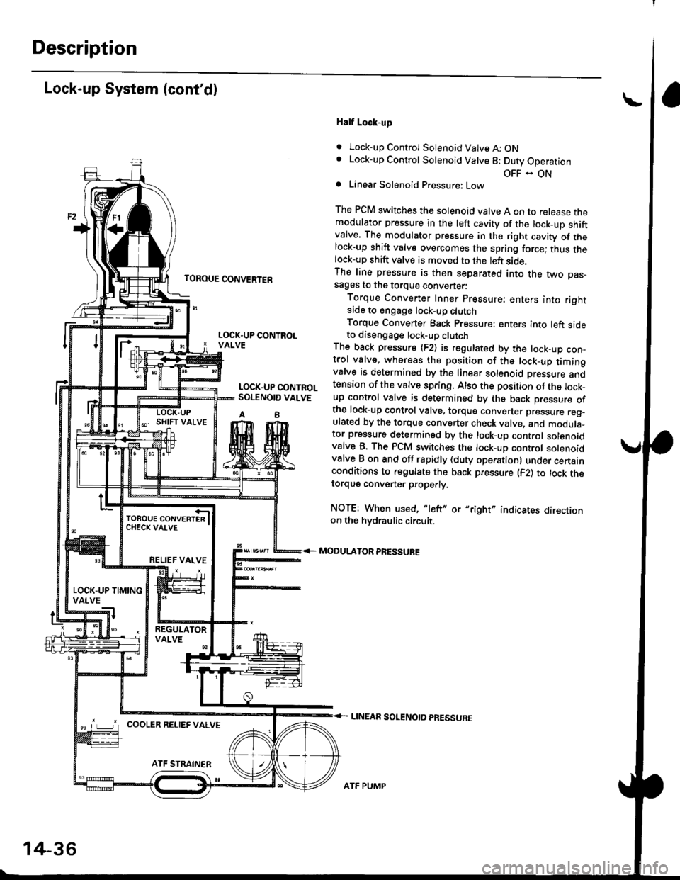
TOROUE CONVERTER
Half Lock-up
. Lock-up Control Solenoid Valve A: ONLock-up Control Solenoid Valve 8: Duty Operation
OFF - ONLinear Solenoid Pressure: Low
The PCM switches the solenoid valve A on to release themodulator pressure in the left cavity of the lock_up shiftvalve. The modulator pressure in the right cavity of thelock-up shift valve overcomes the spring force; thus thelock-up shift valve is moved to the left side.The line pressure is then separated into the two pas-sages to the torque converter:
Torque Converter Inner pressure: enters into rightsade to engage lock-up clutch
Torque Converter Back pressure: enters into left sideto diseogage lock-up clutchThe back pressure (F2) is regulated by the lock-up con-trol valve, whereas the position of the lock-up timingvalve is determined by the linear solenoid Dressure andtension of the valve spring. Also the position of the lock_up control valve is determined by the back pressure ofthe lock-up control valve, torque converter pressure reg_ulated by the torque converter check valve, and modula_tor pressure determined by the lock-up control solenoidvalve B. The PCM switches the lock-up control solenoidvalve B on and off rapidly {duty operation} under certainconditions to regulate the back pressure (F2) to lock thetorque convener properly.
NOTE: When used, "left" or "right" indicates directionon the hvdraulic circuit.
MODULATOR PRESSURE
LINEAR SOLENOTD PRESSURE
LOCK.UP CONTROLVALVE
LOCK.UP CONTROLSOI.TNOID VALVE
A8
TOROUE CONVERTERCHECK VAI-VE
RELIEF VALVE
LOCK-UP TIMINGVALVE
^ L____J'r cooLER RELTEF valvE
14-36
ATF PUMP
Page 721 of 2189

I
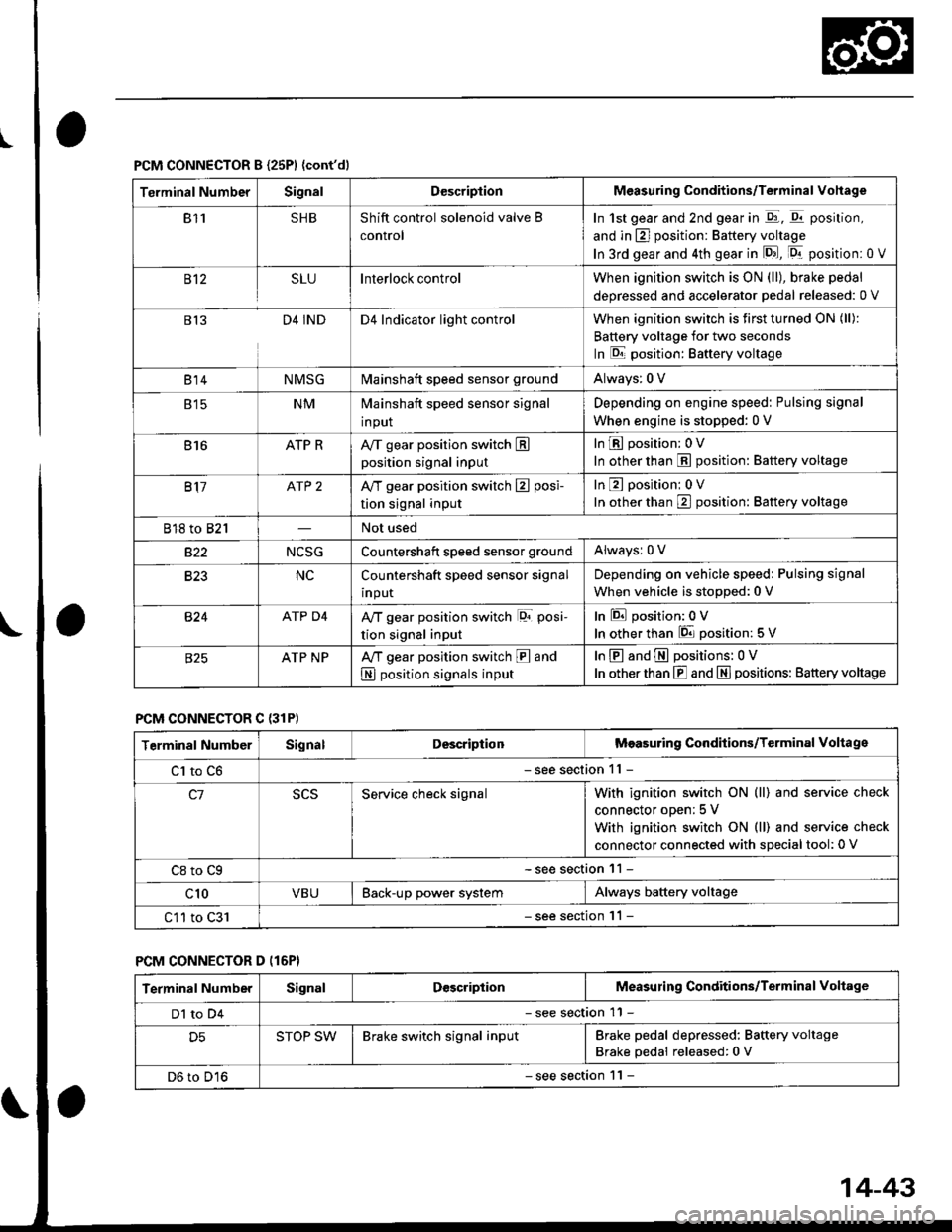
PCM CONNECTOR B {25P1 {cont'dl
Terminal NumberSignalDescriptionMeasuring Conditions/Terminal Vohage
811SHBShift control solenoid valve B
control
In 1st gear and 2nd gear in -q1, q11 position,
and in E] position: Battery voltage
In 3rd gear and 4th gear in lD.J, [Dr- position: 0 V
B't2SLUInterlock controlWhen ignition switch is ON (ll), brake pedal
deoressed and accelerator Dedal released: 0 V
813D4 INDD4 Indicator light controlWhen ignition switch is first turned ON (ll):
Battery voltage for two seconds
In E position: Baftery voltage
B't 4NMSGMainshaft speed sensor groundAlways: 0 V
E tcNMMainshaft speed sensor signal
input
Depending on engine speed: Pulsing signal
When engine is stopped: 0 V
816ATP RAy'T gear position switch Eposition signal input
InE position: 0V
In other than E position: Battery voltage
817ATP 2A/T gear position switch E posi-
tion signal input
InE position: 0V
In orher than E position: Battery voltage
818 to 821Not used
s22NCSGCountershatt speed sensor groundAlwaysr 0 V
B�23NCCountershaft speed sensor signal
input
Depending on vehicle speed: Pulsing signal
When vehicle is stopped: 0 V
B�24ATP D4Ay'T gear position switch lor posi-
tion signal input
InEposition:0V
In other than 6 position: 5 V
ATP NPA,/T gear position switch E and
N position signals input
InE and E positions: 0V
In otherthan E and N] positions: Battery voltage
PCM CONNECTOR C {31P)
Terminal NumberSignalDescriptionMeasuring Conditions/Terminal Voltage
Cl to C6- see section 11 -
c1Service check signalWith ignition switch ON (ll) and service check
connector oDen; 5 V
With ignition switch ON (ll) and service check
connector connected with sDecial tool: 0 V
C8 to Cg- see section 11 -
c10VBUBack-up power systemAlways battery voltage
C11 to C31- see section '11 -
PCM CONNECTOR D (16P}
Terminal NumberSignalDescriptionMeasuring Conditions/Terminal Voltage
Dl to D4- see section 11 -
D5STOP SWBrake switch signal inputBrake pedal depressed: Battery voltage
Brake pedal released: 0 V
D6 to D16- see section 1 l -
14-43
Page 725 of 2189

FCM CONNECTOR D {16P)
\o
14-47
Terminal NumberSignalDo3criptionMeasuring Conditions/Torminal Vohage
D1LCALock-up control solenoid valve A
control
When lock-up is ON: Battery voltage
With no lock-up: 0 V
SHBShift control solenoid valve B
control
In E position, in 1st and 2nd gear in E, E
position: Battery voltage
ln 3rd gear in E, E, in 4th gear in E posi-
tion;0 V
D3LCBLock-up control solenoid valve B
control
When full lock-up: Battery voltage
With half lock-up: Pulsing signal
D4Not used
D5VB SOLLock-up control solenoids, shift
control solenoids and linear
solenoid power supply electrode
with ignition switch oN (ll): Battery voltage
With ignition switch OFF: 0 V
D6ATP RAy'T gear position switch
E position input
tnEposition:0V
In other than E position: Approx. 10 V
SHAShift control solenoid valve A
control
In E] position, in 2nd and 3rd gear in p!, [Q]
position: Battery voltage
In 1st gear in E, @ position, in 4th gear in El
Dosition: 0 V
D8ATP D3A/T gear position switch
E position input
In E position:0V
In otherthan @ position: Approx. 10 V
D9ATP D4Ay'T gear position switch
E position switch
In El position: 0 V
In other than E position: Approx. 5 V
D10NCCountershaft speed sensor signal
input
Depending on vehicle speed: Pulsing signal
When vehicle is stooped: 0 V
D11NMMainshaft speed sensor signal
Inpur
Depending on engine speed: Pulsing signal
When engine is stopped: 0 V
D't2NMSGMainshaft speed sensor ground
D13ATP NPAy'T gear position switch E and
E position input
InE and E positions: 0V
In other than E and E positions: Approx. 10 V
D14AfP 2Ay'T gear position switch
E position input
tnEposition;0V
In other than E position: Approx. 10 V
D16NCSGCountershaft speed sensor
ground
Page 730 of 2189

Symptom-to-Component Ghart
Electrical System -'gG - 98 Models
*1: The DTC in the parentheses is the code E indicator light indicates when the Data Link connector is connected to theHonda PGM Tester.*2: Whenever the Honda PGM Tester or Scan Tool detects an automatic transmission control system DTC, p07OO will beset in the PGM-FI control svstem.
DTCIIE Indicaior
LightMILDotection ltemPage
P1753
fl)BlinksONLock-up control solenoid valve A14-56
P1758
\21BlinksONLock-up control solenoid valve B14-58
P1705
(51BlinksONAy'T gear position switch (short to groundl14-60
P1706
(6)OFFONA,/T gear position switch (open)14-62
P0753
l7lBlinksONShift control solenoid valve A14-64
P0758
{8)ElinksONShift control solenoid valve B14-66
POl20
(9)BlinksONCountershaft speed sensor14-68
P0715
{15)
'96 - 97
models:
OFF'98 model:
Blinks
ON
Mainshaft speed sensor
14-70
P1768
{16)BlinksONLinear solenoid't 4-72
P0740
(40)OFFONLock-up control system14-7 4
P0730
(41)OFFONShift control system14-75
P0700*,
(none)Automatic transmission control svstem in the pGM-Fl
control svstem
14-52
Page 731 of 2189
SYmPtom
E indicator light does not come on tor two seconds after ignition
switch is first turned ON {ll}.
E indicator light is on constantly (not blinking) whenever the ignition
switch is ON (ll).
Shift lever cannot be moved from @ position with the brake pedal
depressed.
Inspection Ref. Page
11-16
14-78
Inspection't4-79
lf the self-diagnostic l-d indicator light does not blink, perform an inspection according to the table below.
NOTE: lf a customer describes the symptom for code Pl706 {6), it will be necessary to recreate the symptom by test-driv-
ing, then recheck the DTC.
14-53
Page 732 of 2189

Symptom-to-Component Chart
Electrical System -'99 - 00 Models
*1: The DTc in the parentheses is the code E indicator tight indicates when the Data Link connector is connected to theHonda PGM Tester.*2: Whenever the Honda PGM Tester or scan Tool detects an automatic transmission control system DTc, p07oo will beset in the PGM-FI control svstem
DTC*IE Indicator
LightMILDotostion ltemPage
P1753
fi)BlinksONLock-up control solenoid valve A'14-80
P1758
t2lBlinksONLock-up control solenoid valve B14-82
P1705
{5}BlinksONAy'T gear position switch {short to ground)14-84
P1706
(6)OFFONy'VT gear position switch {open)14-81
P0753
\71BlinksONShift control solenoid valve A14-89
P0758
(8)BlinksONShift control solenoid valve B14-9r
P0720
(9)BlinksONCountershaft speed sensorr4-93
P0715
(15)B linksONMainshaft speed sensor14-95
P1768
(16)BlinksONLinear solenoid't 4-97
PO7 40(40)OFFONLock-up control system14-99
P0730
(41)OFFONShift control svstem14- 100
P0700*,
(none)OFFAutomatic transmission control system in the pGM_Fl
controt svstem
14-54
Page 733 of 2189
E i"dl.r." fiSh, 1."""". y{*fu
Reference page
14- 101
lE indicator light does not come on for two seconds after ignition switch is first turned oN (ll).14-102
Shift lever cannot be moved from E position with the brake pedal deprsssed'14-104
lf the self-diagnostic E indicator light does not blink and following symptoms appear, perform an inspection according to
the table below.
14-55