Page 639 of 2189

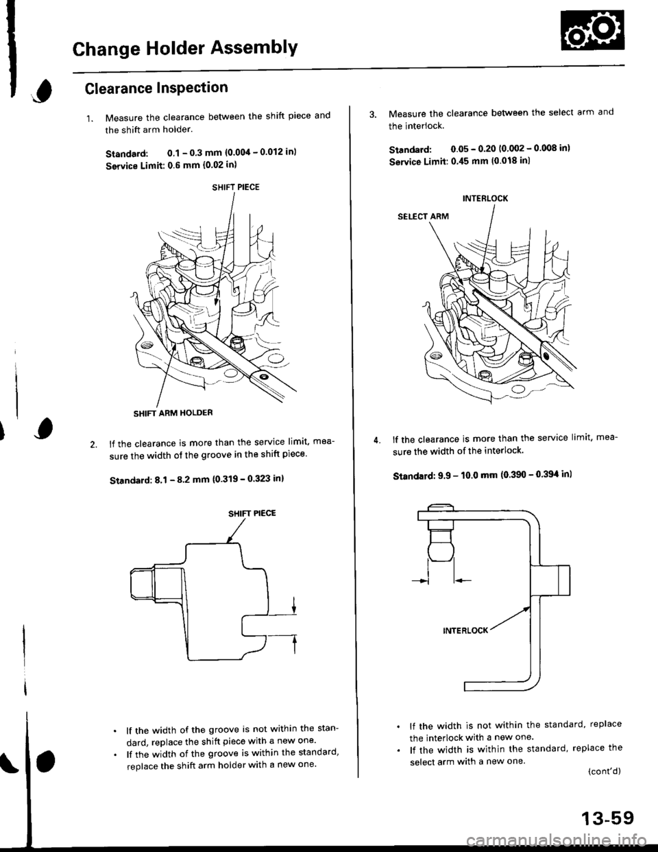
Change Holder AssemblY
,Glearance InsPection
1.Measure the clearance between the shift piece and
the shift arm holder.
Standard: 0.1 - 0.3 mm {0.004 - 0.012 in)
service Limit: 0.6 mm {0.02 in)
lf the clearance is more than the service limit, mea-
sure the width of the groove in the shift piece'
Standard: 8.1 - 8 2 mm {0'319 - 0.323 in}
lf the width of the groove is not within the stan-
dard, replace the shift piece with a new one'
lf the width of the groove is within the standard,
replace the shift arm holder with a new one'
SHIFT PIECE
SHIFT ARM HOLDER
SHIFT PIECE
4.
3. Measure the clearance between the select arm and
the interlock.
Standard: 0.05 - 0.20 10 002 - 0.008 inl
Service Limit:0.45 mm (0.018 inl
lf the clearance is more than the service limit, mea-
sure the width of the interlock.
Standatd: 9.9 - 10.0 mm (0.390 - 0.39't in)
lf the width is not within the standard, replace
the interlock with a new one.
lf the width is within the standard, replace the
select arm with a new one.(cont'd)
INTERLOCK
13-59
Page 640 of 2189

Change Holder Assembly
Clearance Inspection (cont'd)
7. Measure the clearance between the select arm andthe 10 mm shim.
Standard: 0.01 - 0.2 mm (0.0004 - 0.008 in)
lf the clearance is not within the standard, selectand install the appropriate l0 mm shim for the cor-rect clearance from the chart below.
mm Shim
8.
SELECT ARM
l0 mm SHIM
Part NumberThickness
24435-689-0000.8 mm (0.031 in)
B24436-589-0001.0 mm (0.039 in)
c24437-689-0001.2 mm (0.047 in)
D24438-689-0001.4 mm (0.055 in)
E24439-689-0001.6 mm {0.063 in)
13-60
I
9. Measure the clearance between the shift arm holderand the change piece.
Standard; 0.05 - 0.35 (0.fi)2 - 0.014 inlService Limit: 0.8 mm (0.03 in)
lf the clearance is more than the service limit. mea_sure the groove of the change piece.
Standard: 12.05 - 12.15 mm {0.i[7it4 - 0.47txt inl
lf the groove is not within the standard, replacethe change piece with a new one.lf the groove is within the standard, replace theshift arm holder with a new one.
vo
SHIFT ARM HOLOER
CHANGE PIECE
Page 641 of 2189
UO
11. Measure the clearance between the select arm and
the change Piece.
Standard: 0.05 - O'25 mm 10'002 - 0'010 in)
Servica Limii: 0.5 mm {0.02 in)
lf the clearance is more than the service limit, mea-
sure the width of the change Plece.
Standard: 12.05 - 12.15 mm {0.47'|{ - 0 47tI| inl
CHANGE PIECE
lf the width is not within the standard, replace
the change Piece with a new one'
lf the width is within the standard, replace the
select arm with a new one.
't2.
a
a
SELECT ARM
Removal
1. Bemove the shift piece shaft. then remove the shift
piece and the interlock.
SHIFT PIECE SHAFT
INTERLOCK
2. Remove the change holder assembly'
13-61
Page 643 of 2189
Mainshaft, Countershaft, Shift Fork
Removal
1.Remove the mainshaft and the countershaft assem-
blies with the shift forks from the clutch housing.
NOTE: Tape the mainshaft spline before removing
the mainshaft and the countershaft assemblies.
Remove the spring washer and the washer'
v
MAINSHAFT
COUNTERSHAFT
Remove the differential assembly from the clutch
housing.
Tape the
splrnes.
WASHER
DIFF€RENTIAL ASSEMBLY
4. Remove the chamber Plate.
CLUTCH HOUSING
CHAMEEF PLATE
CLUTCH HOUSING
13-63
Page 644 of 2189
Shift Rod
Removal
1. Remove the shift rod boots.
2. Remove the change piece attaching bolt and thespring washer.
3, Bemove the set screw. then remove the spring andthe steel ball.
4, Remove the shift rod, then remove the changepiece,
5. Remove the oil seal.
l_
CHANGE PIECE
SPRINGL. 25.611.01 inl
STEEL(D. s/16
SPRING WASHEN
OIL SEALR€placs.
*ry
SHIFTnoDBOOTS
\,,rl
ATTACHING AOLI
SET SCREW
13-64
Page 645 of 2189
Shift Fork AssemblY
lndex
-A erior ro reassemblinq. clean all the parts in solvent, dry them and apply lubricant to any contact pans
I
mm PIN PUNCH
sTH/REVERSESI{IFT FORK
3RD/4TH SHIFT FORK
Page 646 of 2189

Shift Fork Assembly
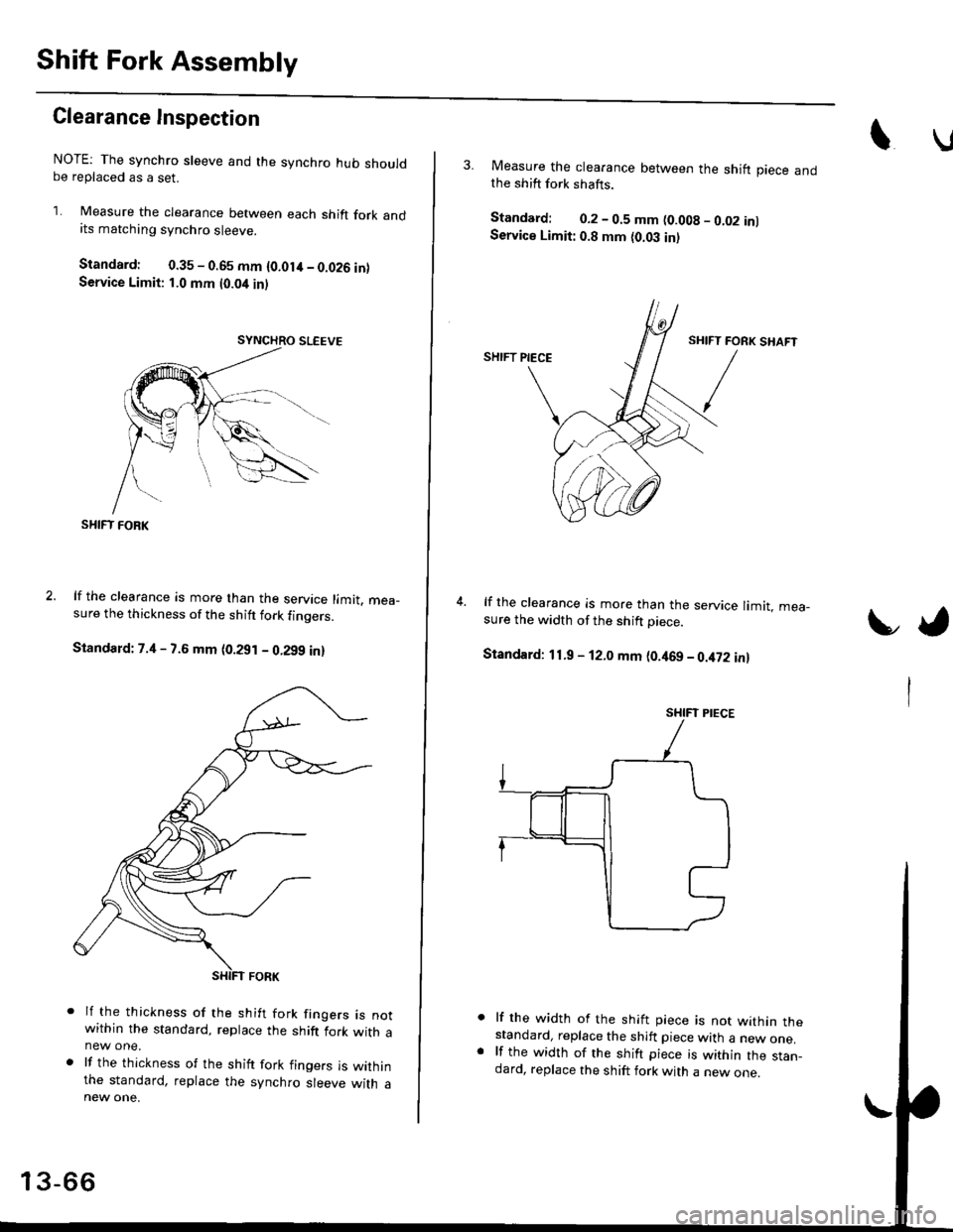
Clearance Inspection
NOTE: The synchro sleeve and the synchro hub shouldbe replaced as a set.
1. Measure the clearance between each shift fork andits matching synchro sleeve.
Standard: 0.35 - 0.65 mm {O.Olit - 0.026 inlService Limit: 1.0 mm t0.04 inl
SHIFT FOBK
lf the clearance is more than the service limit. mea_sure the thickness of the shitt fork finoers.
Standard: 7.4 - 7.6 mm (0.291 - 0.299 in)
lf the thickness of the shift fork frngers rs notwithin the standard, replace the shift fork with anew one.
lf the thickness of the shift fork fingers is withinthe standard, replace the synchro sleeve with a
13-66
3. Measure the clearance between the shift piece andthe shift fork shafts.
Standard: 0.2 - 0.5 mm (0.008 - 0.02 inlService Limit: 0.8 mm {0.03 in)
lf the clearance is more than the service limit. mea-sure the width of the shift Diece.
Standard: 11.9 - 12.0 mm (0.469 - 0.it72 in)
lf the width of the shift piece is not within thestandard, replace the shift piece with a new one.lf the width of the shift piece is within the stan_dard, replace the shift fork with a new one.
t,
SHIFT PIECE
Page 671 of 2189
Transmission
ReassemblY
1. Install the new oil seal
2. Set the change Piece.
3. Install the shift rod
4. Install the steel ball' the spring, and the set screw'
5. Install the spring washer and change piece attach-
ing bolt.
6. Install the shift rod boots.
8x1.0mm31 N.m 13.1 kg-m,22lb-ltl
CHANGEPIECE
@:4OIL SEALReplace.SPRINGWASHER
7. Install the oil chamber Plate'
6 x '1.0 mm12 N.m (1.2 kg-m,9lb-ft|
SPRING
, /L.256fim B()(
@ / t't o'ti"l I
{zw"y-6@
q
10.
Set the spring washer and the washer'
lnstall the mainshaft, the countershaft, and the shift
fork assemblies.
NOTE: Align the finger of the interlock with the
groove in the shift fork shaft.
SHIFT FORKS
13-91