1999 HONDA CIVIC Shift
[x] Cancel search: ShiftPage 373 of 2189

PGM-FI System
System Description
CKP/TDC/CYP Sensor
MAP Sensor
IAT SensorTP SensorEGR Valve Lift Sensor*'Primary H02SSecondary HO2SVSSBARO SensorELD*'KS€Starter SignalALT FR SignalAir Conditioning SignalA/T Gear Position SignalBattery Voltage {lGN.1}Erake Switch SignalPSP Switch SignalFuel Tank Pressure Sensor*iVTEC Pressure Switch*5Clutch Switch Signal*6Countershaft Speed SensornBMainshaft Speed Sensorrs
-\
----t /
F;ilrr j"-----fi-tri-'r.;l
Fb"t."'i" d" c;;il
F,h"'c;;tr*".io";-l
@."r.l"sc;;ll
EaM/PcM B""k-p F"""till
r\
-:/
Fuel IniectorsPGM-Fl Main Belay {Fuel Pump)MILIAC Valve!y'C Compressor Clutch RelayRadiator Fan Relay*,Condenser Fan RelayALT*'lcMEVAP Purge Control Solenoid
Primary HO2S HeaterSecondary H02S HeaterEGR Control Solenoid Valve*rEGR valve*6EVAP Bypass Solenoid Valve*'EVAP Control Canister Vent Shut
VTEC Solenoid Valve*5DLCLock-up Control Solenoid Valve*aShift Control Solenoid Valve*3Linear Solenoid Valve*3
*1: Dl6Y5 engine*2: USA model*3: CW (D16Y5 ensine), D16Y8 engine and 81642 ensine*4: '96 D16Y8 engine lcoupe),'97 Dl6Y7 engine (coupe: KL model, sedan: KL (LX) model),'97 D16Y8 engine {coupe: all models, sedan: KLmodel),'98-all models,'99'all models,'00-all models+5: D16Y5, D16Y8,816A2 engine*6: M/T (D16Y5 enginei*7: CVT 1D'l6Y5 engine)+8: A/T (D16Y7, D16Y8 engine)*9: '96 D16Y5 engine,'96 D16Y7 engine,'96 Dl6Y8 engine (sedan),'97 D16Y5 engine,'97 Dl6Y7 engine (coupe: KA, KC models, sedan:KA, KC, KL (LX) models, hatchback: all models),'97 D16Y8 engine (sedan: KA, KC modelsi
PGM-FI Sy3lem
The PGM-Fl system on this model is a sequential multipon fuel injection system.
Fuel iniector Timing and Duration
The ECM/PCM contains memories for the basic discharge durations at various engine speeds and manifold air flow rates.
The basic discharge duration, after being read out from the memory. is further modified by signals sent from various sen-
sors to obtain the final discharge duration.
ldle Air Control
ldle Air Control Valve llAC Valve)
When the engine is cold. the A,/C compressor is on, the transmission is in gear, the brake pedal is depressed, the P/S load
is high, or the alternator is charging, the ECM/PCM controls current to the IAC Valve to maintain the correct idle speed.
lgnition Timing Control
. The ECM/PCM contains memories for basic ignition timing at various engine speeds and manifold air flow rates.
lgnition timing is also adjusted for engine coolant temperature.
. Aknockcontrol system was adopted which sets the ideal ignition timing for the octane rating ofthegasoline used.*3
Othgr Control Funqtions
1. Starting Control
When the engine is started, the ECM/PCM provides a rich mixture by increasing fuel injector duration.
2. Fuel Pump Control
. When the ignition switch is initially turned on, the ECM/PCM supplies ground to the PGM-Fl main relay that sup-plies current to the fuel pump for two seconds to pressurize the fuel system.. When the engine is running, the ECI\4PCM supplies ground to the PGM-FI majn relay that supplies current to the fuel
oumo.
. When the engine is not running and the ignition is on, the ECM/PCM cuts ground to the PGM-FI main relay which
cuts current to the fuel pump.
11-104
INPUTS
ENGINE CONTROL MODULE (ECMY
POWERTRAIN CONTROL MODULE (PCM) OUTPUTS
Page 485 of 2189
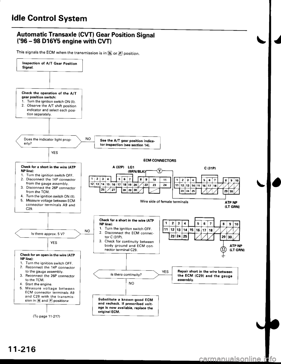
ldle Control System
Automatic Transaxle (CVTI Gear Position Signal
('96 -98 D16Y5 engine with CW)
ATP NP{LT GRNI
INP
GBN)
This signals the ECM when the transmission is in @ or @ position.
Check the operation oI the A/Tgear position switch:1. Turn the ignition switch ON flt).2. Observe the A/T shift positionindicator and select each position separately.
See lhe A/T gear position indica-tor insp€ction {see sec{ion l/tl.
Check tor a short in the wir6 (ATpNP line):1. Turn the ignition switch OFF.2. Disconnect the 14P connectorIrom the gauge assembly.3. Disconnect the 26P connectorfrom the TCM.4. Turn the ignition switch ON fll).5. Measure voltage between ECMconnector terminals A9 andc29.
Check for a short in the wire lATpNP linell1. Turn the ignition switch OFF.2. Disconnect the ECM connector C (31P).
3. Check for continuity betweenbody ground and ECM connector terminal C29.
ls there approx. 5 V?
Check for an open in the wire lATpNP lina):1. Turn the ignition switch OFF_2. Beconnect the 14P connectorto the gauge assembly.3. Reconnect the 26P connectorto the TCM.4. Sta rt the engine.5. Measure voltage betweenECM connector terminals A9and C29 with the transmission in E and E posationt
Repair short in the wire betweenthe ECM {C291 and the gaugeassemblv,
Substitute a known-good ECMand recheck. lf prescribed volt-age is now avrilable, replace theo.iginalECM.
Wire side ot female terminals
2457I910
t112131a15151718
2321252930
ATP(LT io
(To page 11'217)
11-216
Page 581 of 2189
\
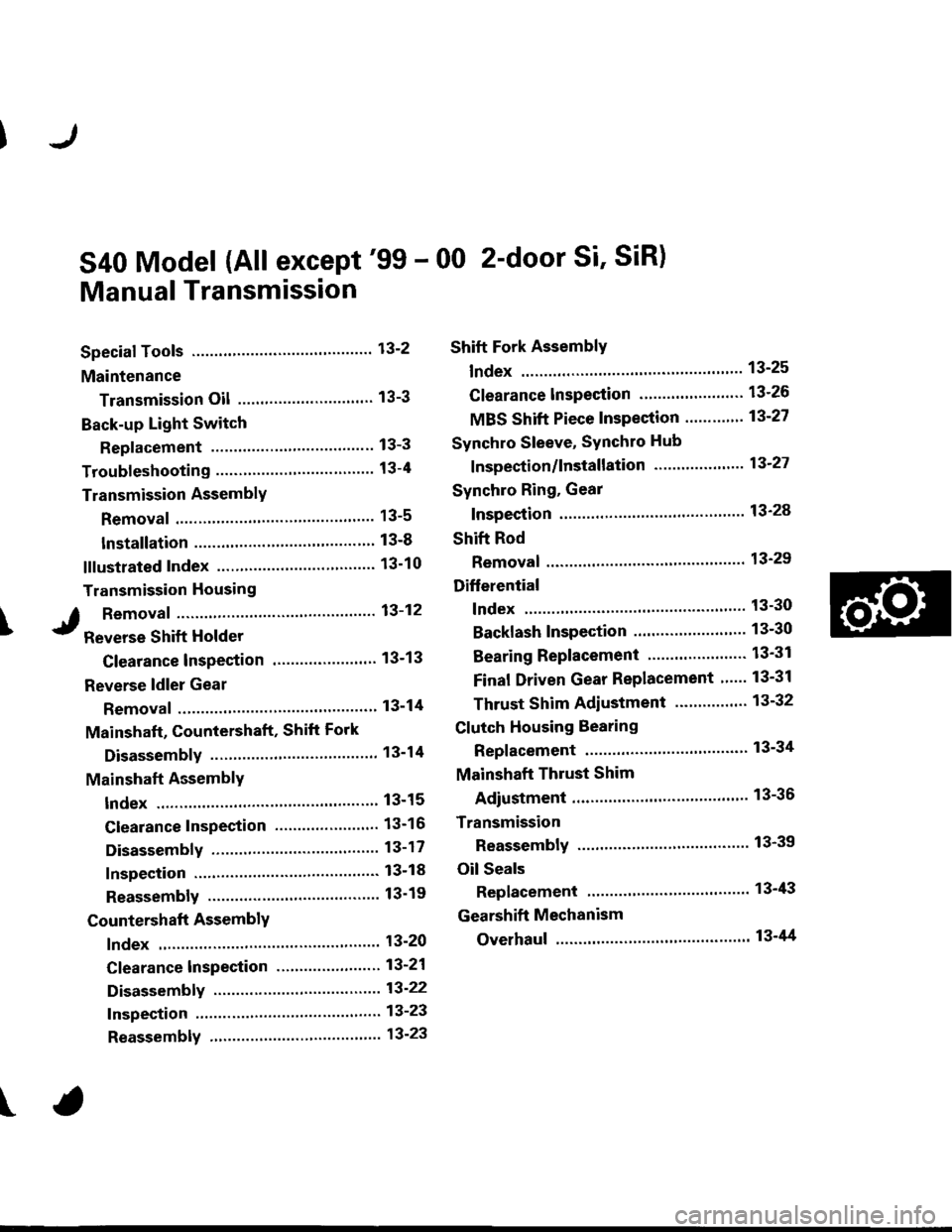
S40 Model (All except'99 - 00 2-door Si' SiR)
Manual Transmission
Special Tools ..'.......... 13-2
Maintenance
Transmission Oil .............................. 13-3
Back-up Light Switch
Replacement ......... 13-3
Troubleshooting '....... 13-4
Transmission AssemblY
Removal ................. 13-5
lnstallation ............. 13-8
lllustrated Index ...............'........."........ 13-10
Transmission Housing
I Removaf .."""""""' 13-12
J R"rr"r"" Shift Holder
Clearance lnspection ....................... 13-13
Reverse ldler Gear
Removal ....'.........." 13-14
Mainshaft, Countershaft, Shift Fork
Disassembly ......'... 13-14
Mainshaft AcsemblY
Index ............... ....... 13-15
Clearance Inspection ..'.................... 13-16
Disassembly .......... 13-17
Inspection ....'......... 13-18
Reassembly ........... 13-19
Countershaft AssemblY
lndex ................ ...... 13-20
Clearance lnspection ."..........'......." 13-21
Disassembly ..."""' 13-22
Inspection .............. 13-23
Reassembly ..'.""... 13-23
Shift Fork AssemblY
lndex ............... ."'... 13-25
Clearance lnspection ."......."........'.. 13'26
MBS Shift Piece Inspection ....-.....'.. 13'27
Synchro Sleeve, Synchro Hub
f nspection/lnstallation .......'...... ".... 13'27
Synchro Ring, Gear
Inspection '....'..".... 13'28
Shift Rod
Removal .'......".""" 13'29
Differential
lndex ......."'...... .'."' 13-30
Backlash Inspection ..........."......."... 13-30
Bearing Beplacement'.............'.".... 13'31
Final Driven Gear Replacement '..... 13-31
Thrust Shim Adiustment ..."........... 13-32
Clutch Housing Bearing
Replacement .......'. 13-34
Mainshaft Thrust Shim
Adiustment '....'..".. 13-36
Transmission
Reassembly ........... 13-39
Oil Seals
Replacement ......... 13-43
Gearshift Mechanism
Overhaul ................ 13-44
\
Page 583 of 2189
MaintenanceBack-up Light Switch
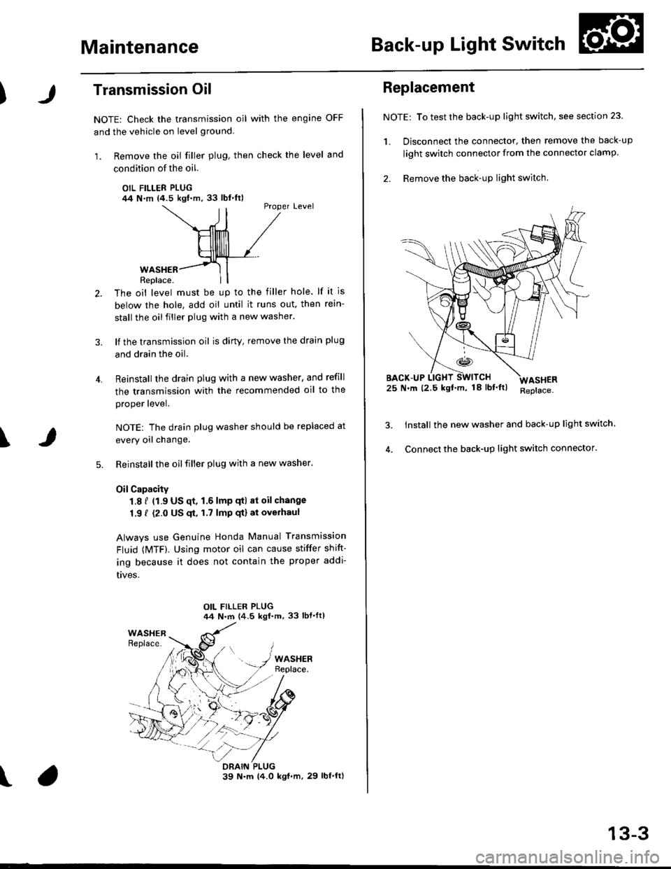
Transmission Oil
NOTE: Check the transmission oil with the engine OFF
and the vehicle on level ground.
1. Remove the oil filler plug, then check the level and
condition of the oil.
OIL FILLER PLUG/14 N.m (4.5 kgl.m,33 lbl.ft)Proper Level
4.
WASHERReplace.
The oil level must be up to the filler hole. lf it is
below the hole, add oil until it runs out. then rein-
stall the oil filler plug with a new washer.
lf the transmission oil is dirty, remove the drain plug
and drain the oil.
Reinstall the drain plug with a new washer, and refill
the transmission with the recommended oil to the
proper lever.
NOTE: The drain plug washer should be replaced at
every oil change.
Reinstall the oil filler plug with a new washer.
OilCapacity
1.8 f (1.9 US qt. 1.6 lmp qtl at oil change
1.9 { (2.0 US $, 1.7 lmp qt) at overhaul
Always use Genuine Honda Manual Transmission
Fluid {MTF). Using motor oil can cause stiffer shift-
ing because it does not contain the proper addi-
t|ves.
\
\
Replacement
NOTE: To test the back-up light switch, see section 23
1. Disconnect the connector, then remove the back-up
light swirch connector from the connector clamp.
2. Remove the back-up light switch.
25 N.m (2.5 kgf'm, 18lbf'ltl
Install the new washer and back-up light switch
Connect the back-up light switch connector.
ASHER
13-3
Page 584 of 2189
Troubleshooting
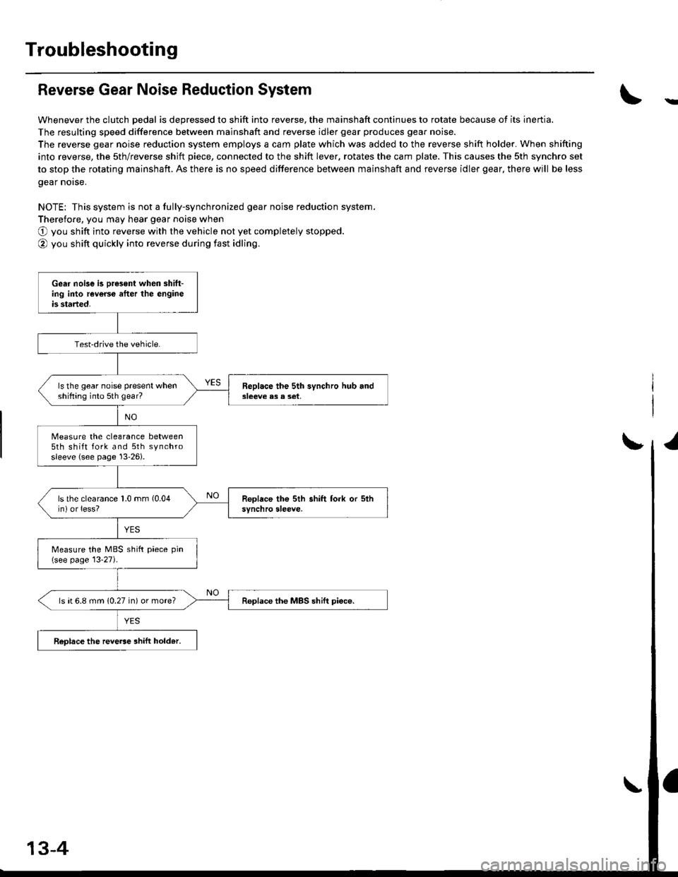
Reverse Gear Noise Reduction System
Whenever the clutch pedal is depressed to shift into reverse, the mainshaft continues to rotate because of its inertia.
The resulting speed difference between mainshaft and reverse idler gear produces gear noise.
The reverse gear noise reduction system employs a cam plate which was added to the reverse shift holder. When shifting
into reverse, the sth/reverse shjft piece, connected to the shift lever, rotates the cam plate. This causes the sth synchro set
to stop the rotating mainshaft. As there is no speed difference between mainshaft and reverse idler gear, there will be less
gear norse.
NOTE: This system is not a fully-synchronized gear noise reduction system.
Therefore, you may hear gear noise when
O you shift into reverse with the vehicle not yet completely stopped.
@ you shift quickly into reverse during fast idling.
-
Gear noise is oresent when shift-ing into reverce after the engineis started.
Test-drive the vehicle.
ls the gear noise present whenshifting into 5th gear?Beplace the 5th synchro hub and3leeve e3 a set,
Measure the clearance between5th shift fork and 5th synchrosleeve {see page 13'26).
ls the clearance 1.0 mm (0.04
in) or less?
Measure the MBS shift piece pin(see page 13-27).
ls ( 6.8 mm (0.27 in) or more?Replace the MBS shift piece.
ReDlace the reve6e ahift hold.r.
13-4
Page 586 of 2189

Transmission Assembly
Removal (cont'dl
8. Remove the driveshafts (see section 161.
NOTE: Coat all the precision finished surfaces with
clean engine oil or grease. Tie plastic bags over the
driveshaft ends,
DRIVESHAFT
10 x 1.25 mrn43 N.m 14.4 kgt.m,32 rbf.frl
COTTER PINReplace. SELF12 x 1.25 mm49-59 N.m (5.0 -6.0 kgt.m,36-43 lbf.ft)
9. Remove exhaust pipe A.
Replace.12 x 1.25 mm64 N.m {6.5 kgt.m,47 lbf.tr)
GASKETSReplace.
IF\sELF-LocKtNG NUT.''1/Replace.8 x 1.25 mm16 N.m {1.6 kgf'm,12 tbf.ft)
EXHAUSTPIPE A
SELF-LOCKING NUTReplace.I x 1.25 mm22 N.m (2.2 kgf.m,16 tbt'fr)
SELF-LOCKING NUTReplace.D16Y5, D16Y7 engines:
33 N.m {3.4 kgf.m,25 lbt.ft)D16YB engine:10 x 1.25 mm54 N.m 15.5 kgl'm,40 lbf.ttl
SET RING
13-6
v'10. Remove the shift rod and extension rod.
SI'IIFT BOD
8x22mmSPRING PINReplace.
EXTENSION ROD
PIN PUNCH, 8.O mm(Commercially available)f-
'1'1. Remove the engine stiffeners and clutch cover.
D16Y5, D16Y8 engines:
10 x 1.25 mm44 N.m (4.5 kgt.m,33 tbf.tr)
I x 1.25 mm24 N.m (2.4 kgf.m17 lbt.frl
COVER
8 x 1.25 mm24 N.m 12.4 kgf'tn,17 tbt.tr)
Page 589 of 2189

. Torque the mounting bolt and nuts in the sequence
shown.
O 12 x 1.25 mm64 N.m {6.5 kgt.m,47 lbf.fr)
@ 12 x 1.25 mm74 N.m (7.5 kgl'm,54 tbt.fr)
Check that the bushings are not twisted or offset.
Install the clip as shown.
SHIFT ROD
Turn the boot so the hole is facing down.
Make sure the boot is installed on the shift rod.
O) 12 x 'l.25 mm64 N.m 16.5 kgl.m,47 tbt.ft)
I
a
a
a
a
8 x 1.25 mmN.m t2.2 kgt.m, l6 lbl'tt)
6 x 1.0 mm9.8 N.m (1.0 kgl.m.7.2 tbf.tr)
. Apply grease to the slave cylinder push rod.
NOTE: Use only Super High Temp Urea Grease
{P/N 08798 - 9002}.
CLUTCHUNE
a
a
(P/N-6tl
08798-9002)
8 x 1.25 mm22 N.m 12.2 kgl.n.16 tbf.frl
. Turn the breather cap so that the "F" mark points at
the front of the car as shown.
Refill the transmission with the recommended oil
(see page 13-3).
Connect the positive (+) cable first, then the negative
(-) cable to the battery.
Check the clutch oDeration,
Shift the transmission and check for smooth opera-
tion.
Check the front wheel alignment (see section 18).
FRONT
13-9
Page 591 of 2189
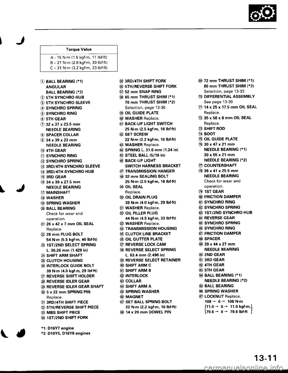
Torque Value
A - 15 N.m (1.5 kgf.m, 1'1 lbf.ft)
B - 27 N.m (2.8 kgf.m. 20 lbift)
C - 31 N.m {3.2 kgnm, 23 lbift)
\
O BALL BEARING (*T)
ANGULAR
BALL BEARING {*2I
O 5TH SYNCHRO HUB
O 5TH SYNCHRO SLEEVE
€) SYNCHRO SPRING
o SYNCHRO B|NG
@ 5TH GEAR
@ gz xgt x 23.5 mm
NEEDLE BEARING
@ SPACER COLLAR
@34x39x23mm
NEEDLE BEARING
(D 4TH GEAR
O SYNCHRO RING
C) SYNCHRO SPRING
CO 3RD/4TH SYNCHRO SLEEVE
@ 3RD/4TH SYNCHRO HUB
(} 3RD GEAR
@34x39x27.5mmNEEDLE BEARING
G) MAINSHAFT
G) WASHER
@ SPRING WASHER
@ BALL BEARING
Check for wear and
operation.(E 26x42x7 mm OIL SEAL
Replace.
@ 28 mm PLUG BOLT
5,1 N.m {5.5 kgf'm, /t0 lbt'ft)
@ lsT/zND SELECT SPRING
L. 36.26 mm (1./P8 in)
@ SHIFT ARM SHAFT
@ CLUTCH HOUSING
@ INTEELOCK GUIDE BOLT
39 N.m (4.0 kgf.m, 29 lbf.ftl
@ REVERSE SHIFT HOLDER
@ REVERSE IDLER GEAR
@ REVERSE IDLER GEAR SHAFT
@ 5 x 22 mm SPRING PIN
Replace.
@ 3RD/4TH SHIFT PIECE
@ 5TH/REVERSE SHIFT PIECE
@ MBS SHIFT PIECE
@ 1ST/2ND SHIFI FORK
*1:D16Y7 engine*2: D16Y5, D16Y8 engines
@ 3RD//|TH SHIFT FORK
@ 5TH/REVERSE SHIFT FORK
@ 52 mm SNAP RING
@ 65 mm THRUST SHIM (*11
70 mm THRUST SHIM (*21
Selection, page 13-36
@ OIL GUIDE PLATE
@ wASHER Replace.
@ BACK.UP LIGHT SWITCH
25 N.m (2.5 kgf'm, 18 lbf'ft)
@ sET SCREW
22 N.m {2.2 kgf.m, 16 lbl.ft}
@ WASHER Replace.
@D SPRING 1.31.6 mm (1.2,1inl
@ STEEL BALL 15/16 in)
@ BACK-UP LIGHT
SWITCH HARNESS BRACKET
@ TRANSMISSION HANGER
@ 32 MM SEALING BOLT
25 N.m (2.5 kgf.m, 18 lbt'ft)
@ OIL SEAL
Replace.
@ OIL DRAIN PLUG
39 N.m (4.0 kgf.m, 29 lbf.ft)
@ WASHER Replace.
@} OIL FILLER PLUG
44 N.m (4.5 kgf.m, 33 lbf'ftl
@ WASHER Replace.
@) TRANSMISSION HOUSING
€) CLUTCH LINE BRACKET
@ OIL GUTTER PLATE
@ REVERSE LOCK CAM
@ REVEBSE SELECT SPRING
L. 63.4 mm {2.,196 in)
@ REVERSE SELECT RETAINER
@ SHIFT ARM C
@ SHIFT ARM B
@ INTERLoCK
@ COLLAR
@ SHIFT ARM A
@ SPRING WASHER
@ MAGNET
@ sET BALL SPRING BOLT
22 N.m (2.2 kgf.m, 16 lbf.ftl
@ 14 x 20 mm DOWEL PIN
@ 72 mm THRUST SHIM l*11
80 mm THRUST SHIM (*21
Selection, page '13-33
@ DIFFERENTIAL ASSEMBLY
See page 13-30
@ 14 x 25 x 17.5 mm OIL SEAL
Replace.
@ 35 x 56 x 8 mm OIL SEAL
Replace.
@ SHIFT ROD
@ BOOr
@ OIL GUIDE PLATE
@30x47x21 mm
NEEDLE BEARING (* 1}
30x55x21 mm
NEEDLE BEARING {'2)
@ COUNTERSHAFT
@36x41 x 25.5 mm
NEEDLE BEARING
Check for wear and
operatron.
@ lsT GEAR
@ FRICTION DAMPER
@ SYNCHRO RING
@ SYNCHRO SPRTNG
@ lST/2ND SYNCHRO HUB
@ REVERSE GEAR
@ SYNCHRO SPRING
@ SYNCHRO RING
@ FRICTION DAMPER
@ SPACER
@39x4lx27mm
NEEDLE BEARING
@ 2ND GEAR
@ 3RD GEAR
@ 4TH GEAR
@ sTH GEAR
@) BALL BEARING {* 1}
NEEDLE BEARING (*2}
@ BALL BEARING
@) SPRING WASHER
@ LoCKNUT Replace.
108 - 0- 108 N.m
ftt.o* o- 1r.o kst.m,l
179.6- 0- 79.6 rbtft I
13-1 1