1999 HONDA CIVIC page 257
[x] Cancel search: page 257Page 525 of 2189

Emission Control System
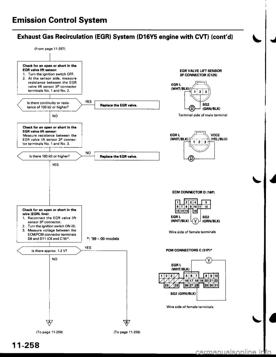
Exhaust Gas Recirculation (EGR) System (D16Y5 engine with GWI (cont'dl
lTl49il T_he scan tool indicates Diagnostic Trouble Code (OTC) P1491: A malfunction in the Exhaust Gas Recirculation- lEgh) svstem.
CvT lM/T see page 1l-2611:
J
EGR VALVELIFT SENSOR#16 HOSE
PUMP/GAUGE,0- 30 in.HsA973X-041-XXXXX
EGRVALVE
The MIL has been reoorted on.DTC P1491 is stoled.
Problem verification:1. Do the ECM/PCM Reset Proce-du re.2. Connect the SCS service con'
3. Start the engine. Hold theengine at 3,000 rpm with noload {in Park or neutral) untilthe radiator fan comes on,4. Drive the vehicle on the roadfor approx. 10 minutes. Try tokeep the engine speed in the1,700 - 2,500 rpm range.
Intermittonl failure, system is OKat this time. Check for Door con-nections or loose wires at, C144{EGR velve} and ECM/PCM.
ls DTC P l49l indicated?
Check fo. vacuum to ihe EGR
1. Disconnect the No. 16 hose fromthe EGR valve.2. Connect a vacuum pump/gauge to the hose.3. Start the engine and let it idle.
ls there any vacuum?
Check tor a malfunction in theEGR control solenoid valve:'1. Disconnect the EGR controlsolenoid valve 2P connector,2. Becheck the No. 16 hose for
Check vacuum hose routing o,the entire EGR svstem. lf hoserouting is OK, replac€ the EGRcontrol solenoidvalv6.
ls there any vacuum?
Substitute a known-good ECM/PCM and recheck. It symptom/indicalion goes away, replacethe original ECM/PCM.
(To page 11 257)
11-256
Page 526 of 2189
![HONDA CIVIC 1999 6.G Workshop Manual \EGR VALVELIFT SENSOR#16 HOSE
I
(From page 11-256)
EGR VALVE LIFT SENSOR3P CONNECTOR lC14.l)
zF vcczI- . ] IYEL/BLU)ll 2l3l---l-r_ 7 |
v-,, ISG2IGRN/BLK) I ^ II{Vts
ECM CONNECTOR D {16P)
PUMP/GAUGE,0 HONDA CIVIC 1999 6.G Workshop Manual \EGR VALVELIFT SENSOR#16 HOSE
I
(From page 11-256)
EGR VALVE LIFT SENSOR3P CONNECTOR lC14.l)
zF vcczI- . ] IYEL/BLU)ll 2l3l---l-r_ 7 |
v-,, ISG2IGRN/BLK) I ^ II{Vts
ECM CONNECTOR D {16P)
PUMP/GAUGE,0](/manual-img/13/6068/w960_6068-525.png)
\EGR VALVELIFT SENSOR#16 HOSE
I
(From page 11-256)
EGR VALVE LIFT SENSOR3P CONNECTOR lC14.l)
zF vcczI- . ] IYEL/BLU)ll 2l3l---l-r_ 7 |
v-,, ISG2IGRN/BLK) I ^ II{Vts
ECM CONNECTOR D {16P)
PUMP/GAUGE,0 - 30 in.Hs4973X-041-XXXXX
sG2(GRN/BLKIvcc2IYEL/BLU}
Wire side ol temale terminals
PCM CONNECTORS C (31P}'
YES
Wire side of female terminals
1
(cont'd)
1-257
Check fo. a mallunction in theEGF valv€:1. ldove the vacuum pump/gauge
to the EGR valve.2. With the engine at idle, apply
26.7 kPa (200 mmHg,8.0 in.Hg)
ofvacuum to the EGR valve.
Does the engine stall or runrough and does the EGR valvehold vacuum?
Check for an open in the wire
IVCC2linel:1. Turn the ignition switch OFF.2. Disconnect the EGR valve liftsensor 3P connector.3. Turn the ignition switch ON (ll).
4. Measure voltage between theEGR valve lift sensor 3P con'
nector terminals No. 3 and
No.2.
ls lhere approx.5 V?
Check for an oDen in the wire
{VCC2 line}:Measure voltage between theECM/PCM connector terminalsD10 and Dl1 (C18 and C28)*.
Rep.ir open in the wire betweenrhe EGR valve snd ECM/PCM
{Dl0 {C28)*).lsthere approx.5 V?
Sub3titute t known-good ECM/PCM end recheck. lt 3ymptom/indication goos eway, replaceth6 original ECM/PCM.(To page 1l-258)*: '99 - 00 models
Page 527 of 2189

Emission Gontrol System
Exhaust Gas Recirculation (EGRI System (Dl6Y5 engine with CW) (cont'dl
EGR VALVE LIFT SENSOR3P CONNECTOR {Cl251
./
EGR L(WHT/BLKI
EGR LIWHT/BLKI
EGR L{WHT/BLKI
sG2
{GRN/BLK}
sG2{GRN/BLK}
Terminal side ol male terminal
ECIT'I CONNECTOR D II6PI
Wir€ side of f€male terminals
PCM CONNECTORS C (31PI*
{To page 11-259)
11-258
{From page 11-257}
Chock lor an opcn or short in th.EGR v.lve lift .€nsor'1. Turn the ignition switch OFF.2. At the sensor sid€, measur€resistance between the EGRvalve lift sensor 3P connectorterminals No. 1 and No.2.
ls there continuity or resis'tance ot 100 k0 or higher?
Chock tor sn op€n or lhort in theEGR valve lift lonror:Measure resistancg between theEGR valve lift s€nsor 3P connec-tor terminals No. 1 and No. 3.
ls there 100 k0 or higher?
Ch.ck tor an ooon or rhon in thcwiro IEGRL linc):1. Beconnect tho EGR v6lve liftsensor 3P connector.2. Turn tho ignition switch ON (ll).
3. Measure voltage between theECM/PCM connector terminalsD9 and Dl1 (C6 and C18l*.
ls there approx. 1.2 V?
(To page 11-259)
Wire side of female terminals
Page 556 of 2189

I
ECM/PCM CONNECTOR A (32P)
2WBS(BLUIWiro side olIemaleterminalsJUMPER _
WIRE
EVAP BYPASS SOLENOIDVALVE 2P CONNECTOR {C793I
Wire side of
femal€terminals
\
ECM/P,CM CONNECTOR a l32Pl
Wir€ side of femaleterminals
(cont'dl
11-2A7
(From page 11-286)
Check the EVAP bypa3s 3olenoid
1. Turn the ignition switch OFF.
2. Connect ECM/PCM connectorterminal A28 and body ground
with a jumper wire.3. Turn the ignition switch ON (ll).ChGck tor an opon in lho wite(lGl lin6l:1. Turn the ignition switch OFF
2. Disconnect the 2P connectortrom the EVAP bypass sole-noid valve.3. Turn the ignition switch ON (ll).
4. Measure voltage between the
EVAP bypass solenoid valve
2P connector terminal No- 1
and body ground.
R.pair open in tha wil€ botwoonEVAP purg. cor|trol 3olenoid valve
.nd tho No. 15 ALTERNATOR SP
SENSOR 17.5 Al tu3e.
Check lor an open in the wire
{2WBS line):l. Turn the ignition switch OFF.
2. Reconnsct the 2P connectorto the EVAP bypass solenoid
3. Turn the ignition switch ON (ll)
4. Measure voltage between
ECM/rcM connector terminalsA28 and Al0.
Ch6ck the following P..ts for
l6akage to atmosPhere, and
roplir or rephco if neca3aary:' fuel fill c.D. tu6l t.nk. tuel vapor pipe. EVAP two way v3lvo. EVAP bypa3! solanoid vtlY., fuel tlnk pra63uro 3on3or. EVAP control canBte.. EVAP control crnistor vent
shut vtlvo. EVAP purgo control lolonoid
. vscuum hoseS and connoction3
Roprir opon in tho wiro betwoen
th. EVAP byp.$ 3ol6noid valve
rnd tho EcM/PcM lA28l.ls there battery voltage?
I2578t011'12tt15t6t8t9202321
2726293o
PGl (BLKI
I
II7l lslel ro lr' I't2r3,"l!j'"EBUP)._3)_!J
Ent ll4al*l 4 l,-'l
2WaS {BLUI
\
Page 915 of 2189

Symptom-to-Component Chart
Electrical System -'96 - 98 Models
*: The DTC in parentheses is the code @ indicator light indicates when the Data Link Connector is connected to the HondaPGM Tester.
DTC*O Indicator
LightMILDetection ltemPage
P1790
(3)BlinksONThrottle position sensor14-242
P179'l
(4)BlinksONVehicle speed sensor14-243
P1705
(5)BlinksONAy'T gear position switch (short to groundl't 4-244
P1706
(6)OFFONA/T gear position switch {open)14-246
P0725
(11)BlinksONlgnition coil14-248
P1793
112lBlinksONManifold absolute pressure sensor14-249
P 1870(30)BlinksONShift control linear solenoid14-250
P'1873
(311BlinksONPH-PL control linear solenoid14-25'l
P1879(32)BlinksONStart clutch control linear sotenoid14-252
P1882BlinksONInhibitor solenoid14-253
P1885
(34)BlinksONDrive pulley speed sensor1l-Zb4
P1886(35)BlinksONDriven pulley speed sensor14-255
P1888
(36)BlinksONSecondary gear shaft speed sensor14-256
T to55
(37)BlinksONECM or TCM14-257
P1890
l42lBlinksONShift control system14-259
P1891
(43)BlinksONStart clutch control svstem14-260
14-23a
Page 934 of 2189

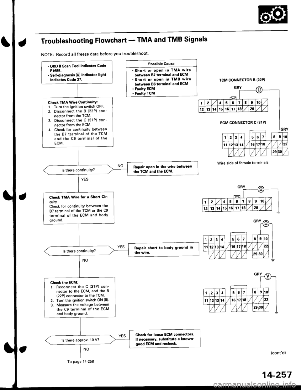
Troubleshooting Flowchart - TMA and TMB Signals
NOTE: Record all freeze data before you troubleshoot'
Possible Cause
. Shorl or op.n in TMA wi.o
botwo6n 87 terminal and ECM. Short or open in TMB wiro
bdtwoon BG to.min.l .nd ECM. F.ulty ECM. Faulty TCM
TCM CONNECTOR B (22P)
GRY
Wire side oI temale terminals
o
I2a58910
1213111516171820
GRY
ECM CONNECTOR C 13lPI
123a56l89r0
1112t3la1618//
29130 /
::)
I2a568910
12t3141516171820
. OBD ll Scsn Tool indicate3 Codo
P1655.. Self-diagnosb E indicator light
indicales Cod6 37.
Check TMA Wire Continuity:1. Turn the ignition switch OFF.
2- Disconnect the I (22P) con-
nector lrom the TCM
3. Disconnect the c (31P) con'
nector from the ECM
4. Check for continuity between
the 87 terminal of the TCM
and the Cg terminal oI the
ECM,
Ropail open in the wire betwcen
the TCM and the ECM.
Check TMA Wir€ for a Short Cir-
cuit:Check for continuity between the
87 terminal of the TCM or the Cg
terminal ol the ECM and bodyground.
check rhe EcM:1. Reconnect the C (31P) con'
nector to lhe ECM, and the B(22P) connector to the TCM
2. Turn the ignition switch ON (ll).
3. Measure the voltage between
the C9 terminal oI the ECM
and body ground.
Chock tor loose ECM connectors.
lf nscossary, subdituta a known'good ECM .nd lecheck.ls there approx. 10 V?
To page 14 258
(cont'd)
14-257
Page 935 of 2189

Electrical Troubleshooting ('96 - 98 Models)
Troubleshooting Flowchart - TMA and TMB Sigrrals (cont,d)
TCM CONNECTOR 8 {22P}
Wire side of female terminals
PNK
PNK
PNK
from page 14 257
Check TMB Wire Continuity:1. Turn the ignirion switch OFF.2. Disconnect the C (31P) connec,tor from the ECM, and the I(22P) connector from the TCM.3. Check for continuity betweenthe 86 terminal ol the TCMand the C30 terminal of theECM,
Repair open in the wire betwe€nrhe TcM and the EcM.
Check TMB Wire tor a Short Cir-cuit:Check for continuity between the86 terminal ot the TCM or theC30 terminal ot the ECM andbody ground.
ls there continuity?
Check the TCM:1. Reconnect the B (22p) con-nector to the TCM, and the C(31P) connector to the ECM.2. Turn the ignition switch ON (ll).3. Measure the voltage betweenthe B6 terminat of the TCMand body ground.
ls there approx. S V?
Check for loose TCM connoctors.lf necessary, substitute e lnown-good TCM and recheck.
o
2I67t8I10
12131416171820
ECM CONNECTOR C 131P}
2a5678I10
ll1213la17118
/l/l )/)/l/l )aol'ol/
PNK
o
2456,8910
1213111516111E20
2157810
1213141516171820
It
Page 1721 of 2189

Power Door Locks
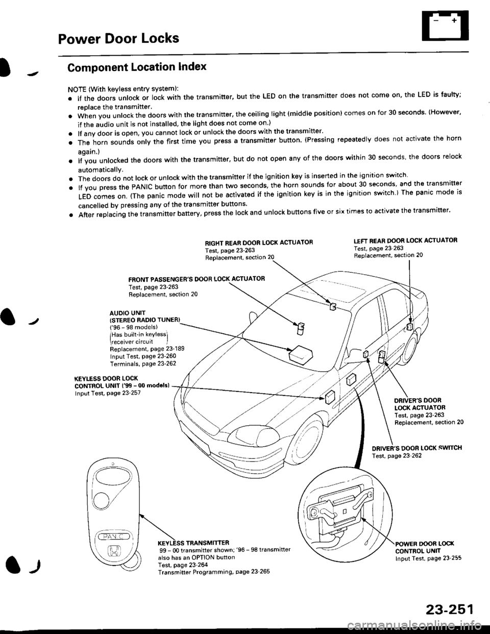
Component Location Index
NOTE (With keyless entry systeml:
. It the doors unlock or lock with the transmitter, but the LED on the transmitter does not come on, the LED is faulty;
replace the transmitter'
. when vou unlock the doors with the transmitter, the ceiling light (middle position) comes on for 30 seconds. (However,
if the audio unit is not installed, the light does not come on )
. lf any door is open, you cannot lock or unlockthe doors with the transmitter'
. The horn sounds only the first time you press a transmitter button. (Pressing repeatedly does not activate the horn
again.)
o lf vou unlocked the doors with the transmitter, but do not open any of the doors within 30 seconds, the doors relock
automatically.
. The doors do not lock or unlock with the transmitter if the ignition key is inserted in the ignition switch
. lf you press the PANIC button for more than two seconds, the horn sounds for about 30 seconds, and the transm'fer
LED comes on. (The panic mode will not be activated iJ the ignition key is in the ignition switch ) The panic mode is
cancelled by pressing any of the transmitter buttons'
o After replacing the transmitter battery, press the lock and unlock buttons five or six times to activate the transmitter'
Replacement, section 20
FRONT PASSENGER'S DOOR LOCK ACTUATOR
RIGHT REAR DOOR LOCK ACTUATOR
Test, page 23-263
I.IFT REAR DOOR LOCK ACTUATOR
Test, page 23 263Replacement, section 20
LOCK ACTUATORTest, page 23-263Replacement, section 20
ORIVER'S DOOR LOCK SWITCH
Test, page 23'262
DOOR L@XCONTROL UN]TInput Test, page 23 255
23-251
Test, page 23-263Replacement, section 20
AUDIO UNIT(STER€O RADIO TUNER)
{'96 - 98 models)
lHas built-in keylessl
eceiver circuit IReplacement, page 23-189
Input Test, page 23-260
Terminals, page 23-262
KEYLESS DOOR LOCKCONTROL UNIT l'99 - 00 modelsl
Input Test, Page 23-257
l-l
TRANSMITTER99 - 0O transmitter shown;'96 -98 transmifter
also has an OPTION buttonTest, page 23-264Transmitter Programming, page 23_265
Qi,,a/
/----
L(ru
i'.-8,-'l
/'-'6