1999 DODGE RAM engine
[x] Cancel search: enginePage 633 of 1691
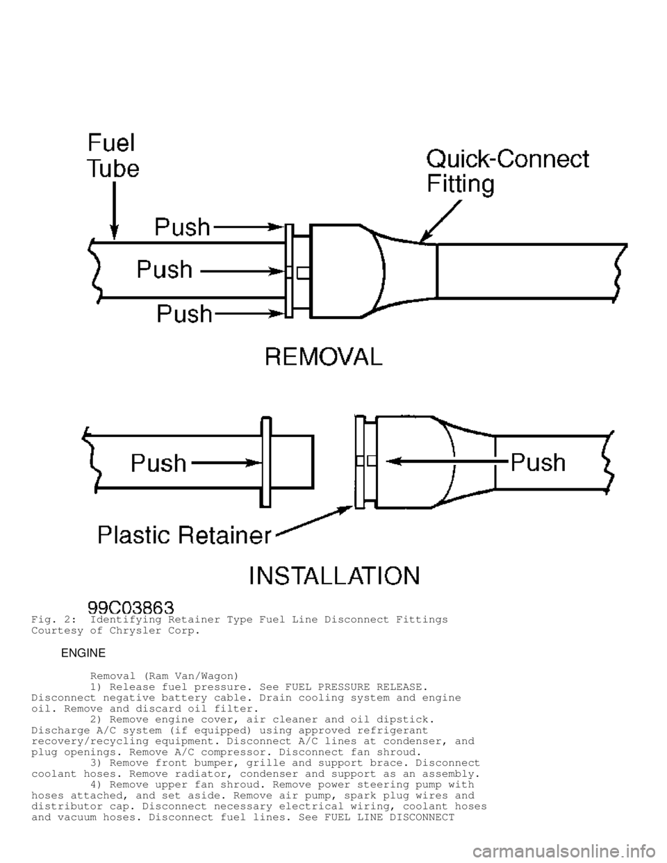
Fig. 2: Identifying Retainer Type Fuel Line Disconnect Fittings
Courtesy of Chrysler Corp.
ENGINE
Removal (Ram Van/Wagon)
1) Release fuel pressure. See FUEL PRESSURE RELEASE.
Disconnect negative battery cable. Drain cooling system and engine
oil. Remove and discard oil filter.
2) Remove engine cover, air cleaner and oil dipstick.
Discharge A/C system (if equipped) using approved refrigerant
recovery/recycling equipment. Disconnect A/C lines at condenser, and
plug openings. Remove A/C compressor. Disconnect fan shroud.
3) Remove front bumper, grille and support brace. Disconnect
coolant hoses. Remove radiator, condenser and support as an assembly.
4) Remove upper fan shroud. Remove power steering pump with
hoses attached, and set aside. Remove air pump, spark plug wires and
distributor cap. Disconnect necessary electrical wiring, coolant hoses
and vacuum hoses. Disconnect fuel lines. See FUEL LINE DISCONNECT
Page 634 of 1691
FITTINGS. Remove air cleaner, throttle body, drive belts, generator,
fan and fan pulley. Remove lower fan shroud.
CAUTION: When removing engine, DO NOT lift engine by intake manifold.
5) Remove intake manifold. See INTAKE MANIFOLD. Raise and
support vehicle. Remove starter. Remove exhaust pipe and heat shields.
Disconnect transmission shift linkage. Remove crank sensor.
6) On A/T models, remove transmission inspection cover. Mark
torque converter-to-flexplate position for installation reference.
Remove torque converter-to-flexplate bolts. On M/T models, disconnect
clutch release mechanism at clutch housing.
7) Attach engine hoist to cylinder heads (at intake manifold
flanges). On all models, support transmission using a floor jack.
Remove transmission or clutch housing-to-cylinder block bolts. Remove
engine mount bolts. Remove engine out front of vehicle.
Installation
To install, reverse removal procedure. Tighten bolts/nuts to
specification. See TORQUE SPECIFICATIONS table. On A/T models, ensure
reference marks on torque converter and flexplate are aligned.
Evacuate and charge A/C system.
Removal ( Dakota 2WD, Durango 2WD, Grand Cherokee & Ram
Pickup)
1) Release fuel pressure. See FUEL PRESSURE RELEASE.
Disconnect and remove battery. On all except Pickup, scribe hood
hinges for installation reference and remove hood.
2) On all models, drain cooling system. Disconnect coolant
hoses. Remove radiator, fan and shroud. Discharge A/C system (if
equipped) using approved refrigerant recovery/recycling equipment.
Disconnect A/C lines, and plug openings. On Pickup, remove upper core
support, transmission cooler and A/C condenser. On all models, remove
belt, air cleaner, vacuum lines, distributor cap and wiring.
3) Disconnect necessary electrical wiring. Disconnect fuel
lines. See FUEL LINE DISCONNECT FITTINGS. Remove throttle body and
linkage. Remove intake manifold. Remove starter, generator, charcoal
canister and horns. Disconnect power steering hoses (if equipped).
Raise and support vehicle. Drain oil. Disconnect exhaust pipe at
exhaust manifold.
4) On A/T models, remove transmission housing inspection
plate. Mark torque converter-to-flexplate position for installation
reference. Remove torque converter-to-flexplate bolts. Remove bracket
for transmission cooler lines.
NOTE: It may be necessary to remove manual transmission if
transmission cannot be supported using floor jack.
5) On M/T models, disconnect clutch release mechanism at
clutch housing. On all models, support transmission using a floor
jack. Remove transmission or clutch housing-to-cylinder block bolts.
Install engine lifting fixture, and attach chain.
CAUTION: When removing engine, DO NOT lift engine by intake manifold.
6) On Ram Pickup and Grand Cherokee, remove front engine
mount bolts. Remove engine from vehicle. On Dakota 2WD and Durango 2WD
models, remove front engine mount through-bolts. See Fig. 3. Remove
engine from vehicle.
Installation
To install, reverse removal procedure. Tighten bolts/nuts to
specification. See TORQUE SPECIFICATIONS table. On A/T models, ensure
Page 635 of 1691

reference marks on torque converter and flexplate are aligned.
Evacuate and charge A/C system.
Removal (Durango 4WD & Dakota 4WD)
1) Release fuel pressure. See FUEL PRESSURE RELEASE.
Disconnect and remove battery. Scribe hood hinges for installation
reference and remove hood.
2) Drain cooling system. Disconnect coolant hoses. Remove
radiator, fan and shroud. Discharge A/C system (if equipped) using
approved refrigerant recovery/recycling equipment. Disconnect A/C
lines, and plug openings. Remove air cleaner, vacuum lines,
distributor cap and wiring.
3) Disconnect necessary electrical wiring. Disconnect fuel
lines. See FUEL LINE DISCONNECT FITTINGS. Disconnect accelerator
linkage. Remove throttle body. Remove starter and generator.
Disconnect power steering hoses. Raise and support vehicle. Drain oil.
Disconnect exhaust pipe at exhaust manifold.
NOTE: Engine, transmission and front axle are connected and
supported with insulators and brackets. See Fig. 3.
4) On left side, remove 2 bolts attaching differential pinion
nose bracket-to-bellhousing bolts. Remove pinion nose bracket-to-
adapter bolts (located on top of differential, near pinion). Separate
engine from engine mount by removing engine mount through-bolt and nut
located on top of engine mount.
5) On right side, remove 2 axle-to-bracket bolts and bracket-
to-bellhousing bolt. Separate engine from engine mount by removing
engine mount through-bolt and nut located on top of engine mount.
Remove engine from vehicle.
Page 636 of 1691
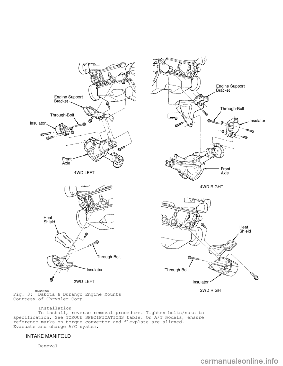
Fig. 3: Dakota & Durango Engine Mounts
Courtesy of Chrysler Corp.
Installation
To install, reverse removal procedure. Tighten bolts/nuts to
specification. See TORQUE SPECIFICATIONS table. On A/T models, ensure
reference marks on torque converter and flexplate are aligned.
Evacuate and charge A/C system.
INTAKE MANIFOLD
Removal
Page 637 of 1691

1) Release fuel pressure. See FUEL PRESSURE RELEASE.
Disconnect negative battery cable. Drain cooling system. Disconnect
accelerator, cruise control, and transmission kickdown cables.
Disconnect fuel lines at throttle body. See FUEL LINE DISCONNECT
FITTINGS.
2) Remove engine cover (Ram Van/Wagon), air cleaner and
generator. Disconnect necessary electrical wiring, coolant hoses and
vacuum hoses. Remove distributor cap and spark plug wires. Remove
valve covers (if necessary).
3) Remove bolts, intake manifold and gaskets. Separate
throttle body from intake manifold (if necessary). Turn intake
manifold upside-down and remove plenum pan (if necessary).
Fig. 4: Plenum Pan Bolt Tightening Sequence
Courtesy of Chrysler Corp.
Installation
1) Install plenum pan and install all bolts finger tight.
Page 640 of 1691
CAUTION: Install NEW studs in cylinder head if studs came out when
removing exhaust manifold. Apply sealant to coarse threads of
studs before installing in head.
Installation
To install, reverse removal procedure. Ensure conical washers
are installed in original locations. Tighten bolts/nuts to
specification, starting at center and working outward. See TORQUE
SPECIFICATIONS table.
CYLINDER HEAD
Removal
1) On Van, remove engine cover and heat shields. On all
models, disconnect battery, and drain coolant. Remove generator
bracket support rod and generator. Remove intake and exhaust manifold.
See INTAKE MANIFOLD and EXHAUST MANIFOLD.
2) Remove rocker arms and push rods. See ROCKER ARMS. Remove
cylinder head bolts, cylinder head and gasket.
Inspection
Check cylinder head warpage. Repair or replace cylinder head
if warpage exceeds specification. See CYLINDER HEAD table under ENGINE
SPECIFICATIONS.
Installation
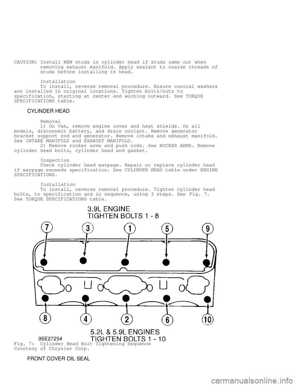
To install, reverse removal procedure. Tighten cylinder head
bolts, to specification and in sequence, using 3 steps. See Fig. 7.
See TORQUE SPECIFICATIONS table.
Fig. 7: Cylinder Head Bolt Tightening Sequence
Courtesy of Chrysler Corp.
FRONT COVER OIL SEAL
Page 641 of 1691
Removal
Disconnect negative battery cable. Remove drive belts from
crankshaft pulley. Remove fan and shroud. Remove crankshaft pulley and
vibration damper. Pry oil seal from front cover.
Installation
1) Use Seal Installer (6635) for seal installation. Installe\
r
should fit with minimum interference. If installer does not fit, front
cover must be removed and installed properly.
2) Position small diameter of oil seal over seal installer.
Using vibration damper bolt, tighten seal installer to draw seal into
position. Remove vibration damper bolt and seal installer. To complete
installation, reverse removal procedure.
FRONT COVER
Removal
1) Disconnect battery. Drain coolant. Remove power steering
pump (if equipped). Remove water pump. See WATER PUMP.
2) Remove crankshaft pulley and vibration damper. Loosen oil
pan bolts. Remove oil pan-to-front cover bolts on each side of oil
pan. Remove bolts, front cover and gasket. DO not damage oil pan
gasket.
Installation
1) Ensure sealing surfaces are clean. Apply a 1/8" (3.17 mm)\
bead of RTV sealant to oil pan gasket. Install gasket, front cover and
bolts. DO NOT tighten bolts at this time.
2) Install front cover oil seal. See FRONT COVER OIL SEAL.
Tighten front cover, oil pan and then vibration damper bolts to
specification. See TORQUE SPECIFICATIONS table. To complete
installation, reverse removal procedure.
TIMING CHAIN
Inspection
1) Remove front cover. See FRONT COVER. Position ruler at
camshaft sprocket, near timing chain link, to check timing chain
stretch.
NOTE: When applying torque to camshaft sprocket bolt, DO NOT allow
crankshaft to move. It may be necessary to hold crankshaft.
2) Place torque wrench on camshaft sprocket bolt. Apply 30
ft. lbs. (41 N.m) torque with cylinder heads installed, or 15 ft. lbs.\
(20 N.m) with cylinder heads removed, on camshaft sprocket bolt in
direction of engine rotation. Note reading on ruler.
3) Apply same amount of torque in opposite direction and note
amount of timing chain movement on ruler. If movement exceeds 1/8" (3.
17 mm), replace timing chain.
Removal
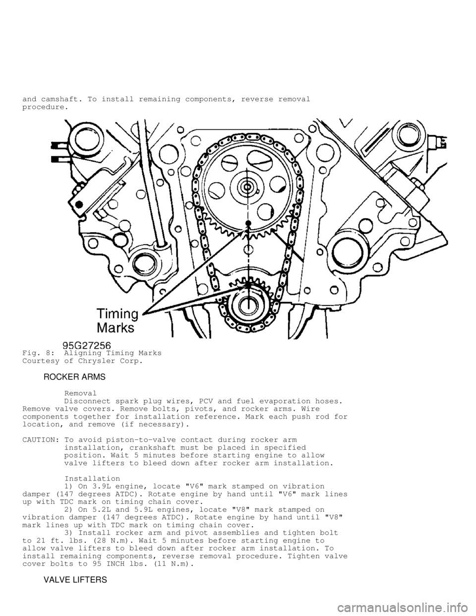
Rotate crankshaft so timing marks are aligned. See Fig. 8.
Remove camshaft sprocket bolt, camshaft sprocket, timing chain and
crankshaft sprocket.
Installation
1) Install timing chain and sprockets. Ensure timing marks
are aligned. See Fig. 8. Install camshaft sprocket bolt and tighten to
specification. See TORQUE SPECIFICATIONS table.
2) Ensure camshaft end play is within specification. See
CAMSHAFT table under ENGINE SPECIFICATIONS. If end play is not within
specification, replace thrust plate located between camshaft sprocket
Page 642 of 1691
and camshaft. To install remaining components, reverse removal
procedure.
Fig. 8: Aligning Timing Marks
Courtesy of Chrysler Corp.
ROCKER ARMS
Removal
Disconnect spark plug wires, PCV and fuel evaporation hoses.
Remove valve covers. Remove bolts, pivots, and rocker arms. Wire
components together for installation reference. Mark each push rod for
location, and remove (if necessary).
CAUTION: To avoid piston-to-valve contact during rocker arm
installation, crankshaft must be placed in specified
position. Wait 5 minutes before starting engine to allow
valve lifters to bleed down after rocker arm installation.
Installation
1) On 3.9L engine, locate "V6" mark stamped on vibration
damper (147 degrees ATDC). Rotate engine by hand until "V6" mark lines\
up with TDC mark on timing chain cover.
2) On 5.2L and 5.9L engines, locate "V8" mark stamped on
vibration damper (147 degrees ATDC). Rotate engine by hand until "V8"
mark lines up with TDC mark on timing chain cover.
3) Install rocker arm and pivot assemblies and tighten bolt
to 21 ft. lbs. (28 N.m). Wait 5 minutes before starting engine to
allow valve lifters to bleed down after rocker arm installation. To
install remaining components, reverse removal procedure. Tighten valve
cover bolts to 95 INCH lbs. (11 N.m).
VALVE LIFTERS