1999 DODGE RAM battery
[x] Cancel search: batteryPage 924 of 1691
CAUTION: If turbocharger failure exists, intercooler must be cleaned.
See INTERCOOLER under AIR INDUCTION SYSTEMS.
Removal
1) Disconnect negative battery cables. Disconnect air inlet
tube and exhaust pipe from turbocharger. Disconnect intercooler inlet
duct from turbocharger. See Fig. 2.
2) Disconnect and plug turbocharger oil supply line and
turbocharger oil drain line at turbocharger. Remove turbocharger
retaining nuts, turbocharger and gasket from exhaust manifold. Plug
all air intake openings.
Installation
1) Apply anti-seize compound on turbocharger mounting studs.
Using NEW gasket, install turbocharger. Install and tighten
turbocharger retaining nuts to specification. See TORQUE
SPECIFICATIONS.
2) Using NEW gasket, install turbocharger oil drain line on
turbocharger. Install and tighten turbocharger oil drain line bolts to
specification. See TORQUE SPECIFICATIONS.
CAUTION: Turbocharger must be pre-lubricated by pouring clean engine
oil in turbocharger oil supply line fitting on turbocharger
before starting the engine.
WARNING: DO NOT rotate turbine wheel in turbocharger with your finger,
as sharp edges may exist.
3) Pour 3 ozs. (60 cc) of clean engine oil into turbocharger\
oil supply line fitting on turbocharger while using soft object to
rotate turbine wheel in turbocharger. This must be done to pre-
lubricate the turbocharger.
4) Install turbocharger oil supply line on turbocharger and
tighten nut to specification. See TORQUE SPECIFICATIONS. To install
remaining components, reverse removal procedure. Tighten bolts/nuts to
specification. See TORQUE SPECIFICATIONS.
TURBOCHARGER WASTEGATE ADJUSTMENT
NOTE: For turbocharger wastegate adjustment, see CONTROL ROD
ADJUSTMENT under TURBOCHARGER WASTEGATE in ON-VEHICLE
ADJUSTMENTS - DIESEL article.
ENGINE SENSORS & SWITCHES
ENGINE COOLANT TEMPERATURE SENSOR
Removal & Installation
1) Engine coolant temperature sensor is located at front of
cylinder head near thermostat. See Fig. 3.
2) Partially drain cooling system until coolant level is
below the cylinder head. Disconnect ECT sensor electrical connector.
Remove ECT sensor from cylinder head. Discard "O" ring. To install,
reverse removal procedure. Use new "O" ring.
CRANKSHAFT POSITION SENSOR (CKP)
NOTE: Crankshaft Position (CKP) sensor may be referred to as engine\
speed sensor.
Removal & Installation
1) CKP sensor is located on left rear side of engine block
Page 925 of 1691
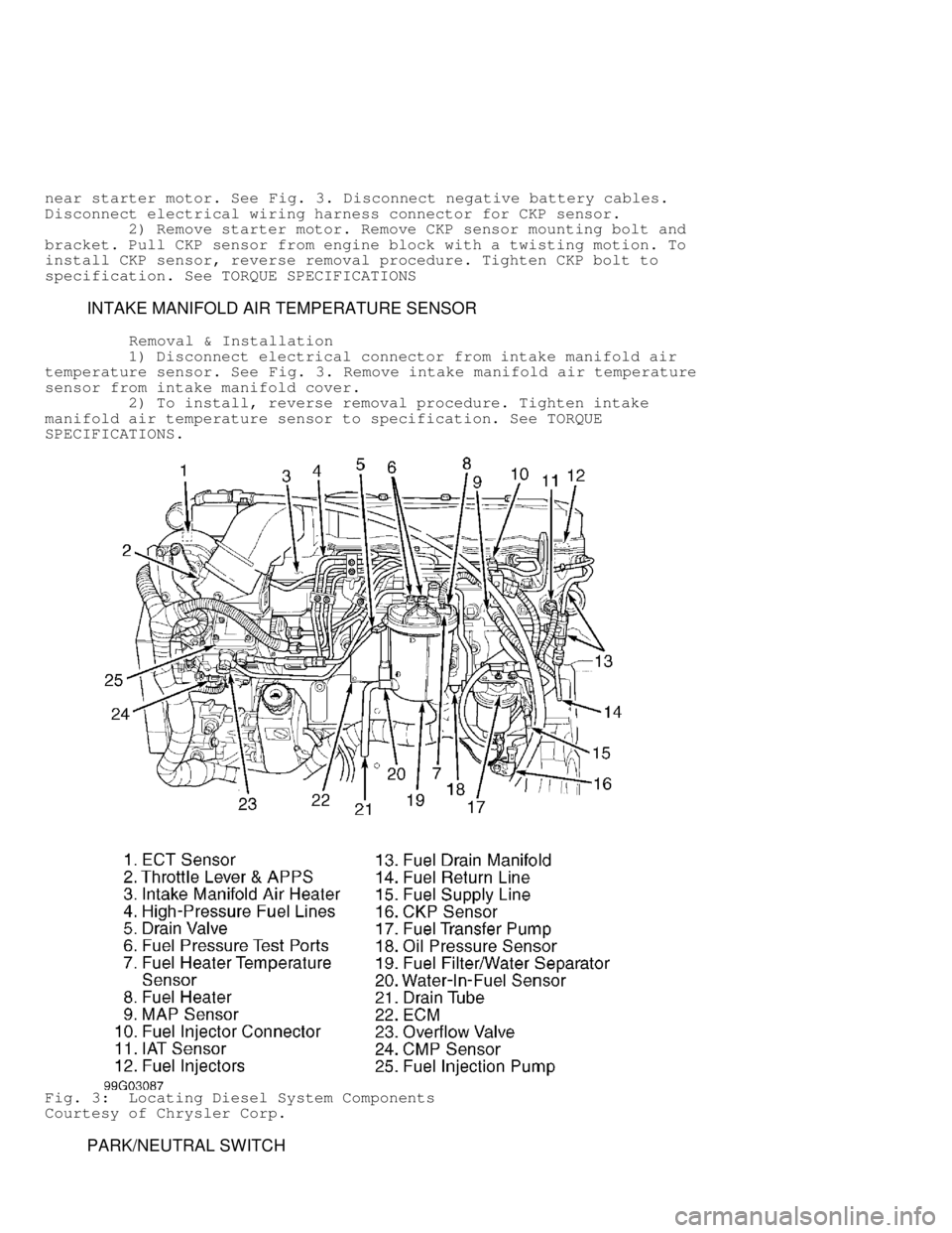
near starter motor. See Fig. 3. Disconnect negative battery cables.
Disconnect electrical wiring harness connector for CKP sensor.
2) Remove starter motor. Remove CKP sensor mounting bolt and
bracket. Pull CKP sensor from engine block with a twisting motion. To
install CKP sensor, reverse removal procedure. Tighten CKP bolt to
specification. See TORQUE SPECIFICATIONS
INTAKE MANIFOLD AIR TEMPERATURE SENSOR
Removal & Installation
1) Disconnect electrical connector from intake manifold air
temperature sensor. See Fig. 3. Remove intake manifold air temperature
sensor from intake manifold cover.
2) To install, reverse removal procedure. Tighten intake
manifold air temperature sensor to specification. See TORQUE
SPECIFICATIONS.
Fig. 3: Locating Diesel System Components
Courtesy of Chrysler Corp.
PARK/NEUTRAL SWITCH
Page 926 of 1691
Removal (A/T Models)
Raise and support vehicle. Disconnect electrical connector
from park/neutral switch. Park/neutral switch is located on side of
transmission case, near shift linkage. Unscrew park/neutral switch
from transmission case. Remove seal ring from park/neutral switch.
Installation
1) Apply parking brake. Place shift lever in Park and
Neutral. Ensure park/neutral switch operating levers in transmission
are centered in the park/neutral switch opening on transmission case.
2) Using NEW seal ring, install park/neutral switch. Tighten
park/neutral switch to specification. See TORQUE SPECIFICATIONS.
Install electrical connector. Add ATF as necessary.
ACCELERATOR PEDAL POSITION SENSOR (APPS)
NOTE: APPS is replaced as assembly, including lever, brackets, and
sensor.
Removal
1) Disconnect negative battery cables. Remove cable cover.
Using finger pressure only, disconnect end of speed control servo
cable from throttle lever pin by pulling forward on connector while
holding lever rearward. Using 2 small screwdrivers, pry throttle cable
connector socket from throttle lever ball.
2) Disconnect transmission kickdown cable (if equipped).
Compress pinch tabs on cruise control and throttle cables. Pull cables
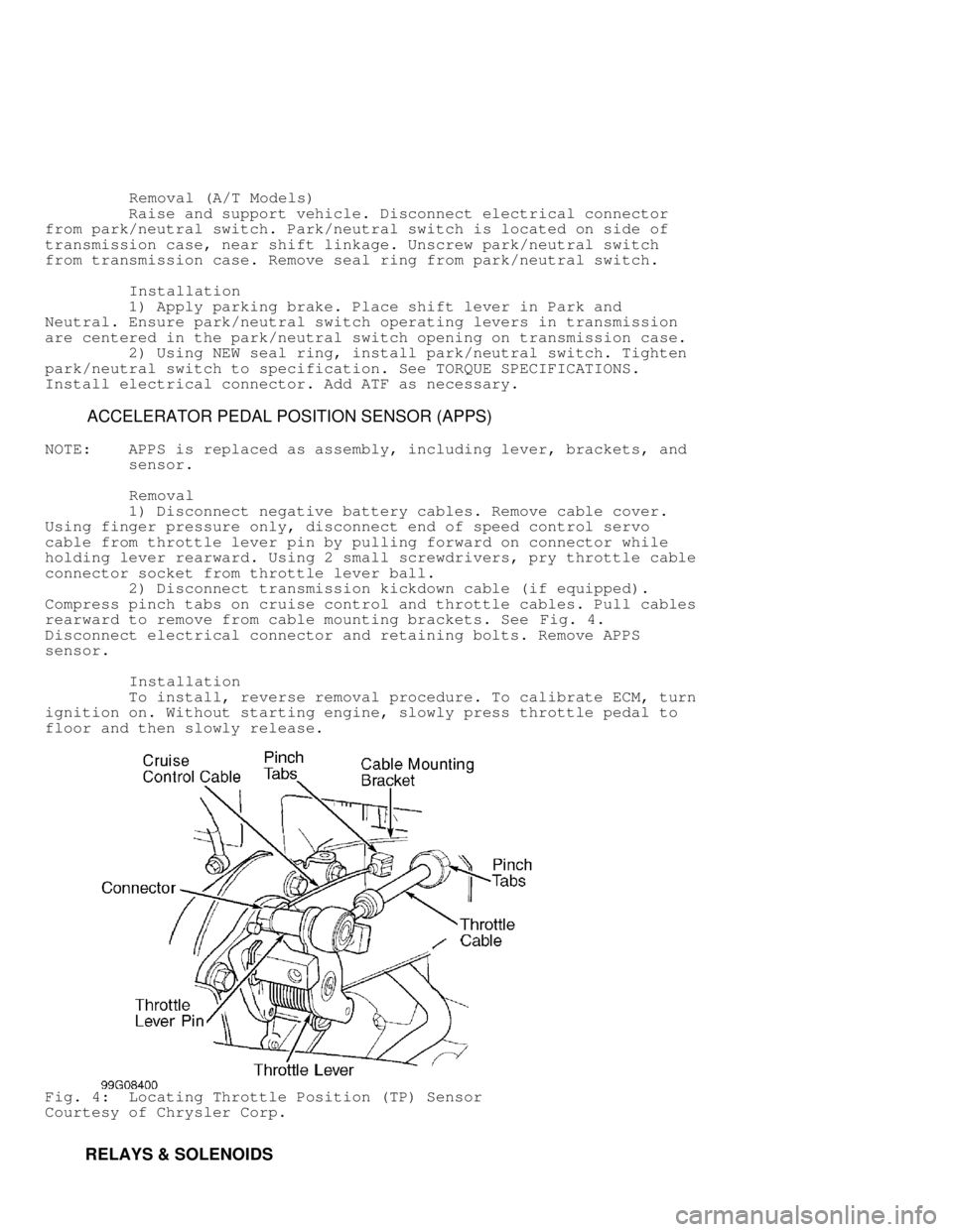
rearward to remove from cable mounting brackets. See Fig. 4.
Disconnect electrical connector and retaining bolts. Remove APPS
sensor.
Installation
To install, reverse removal procedure. To calibrate ECM, turn
ignition on. Without starting engine, slowly press throttle pedal to
floor and then slowly release.
Fig. 4: Locating Throttle Position (TP) Sensor
Courtesy of Chrysler Corp.
RELAYS & SOLENOIDS
Page 927 of 1691
FUEL HEATER RELAY
Removal & Installation
Fuel heater relay is located in Power Distribution Center
(PDC). Check label under PDC cover for relay location. To install,
reverse removal procedure.
INTAKE MANIFOLD AIR HEATER RELAYS
Removal & Installation
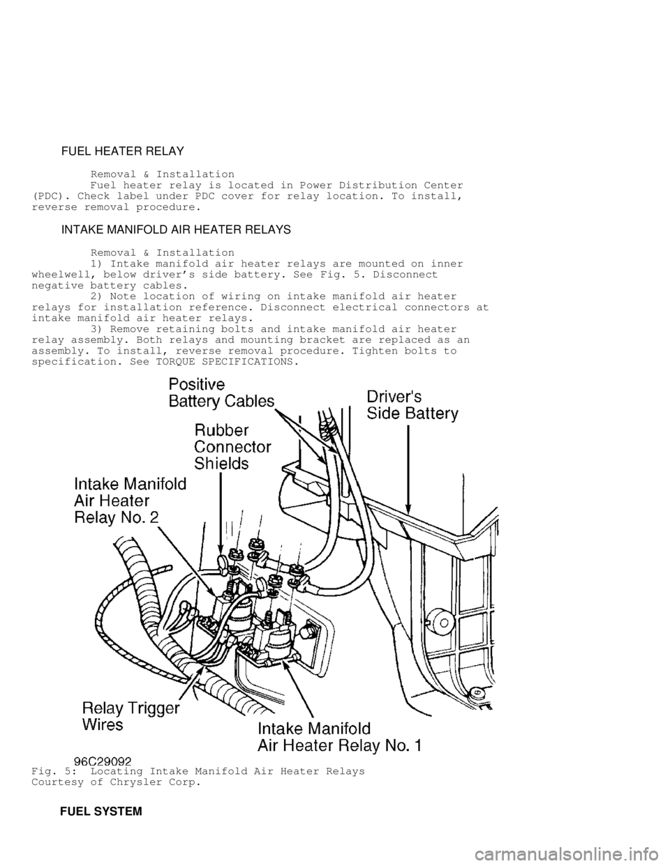
1) Intake manifold air heater relays are mounted on inner
wheelwell, below driver's side battery. See Fig. 5. Disconnect
negative battery cables.
2) Note location of wiring on intake manifold air heater
relays for installation reference. Disconnect electrical connectors at
intake manifold air heater relays.
3) Remove retaining bolts and intake manifold air heater
relay assembly. Both relays and mounting bracket are replaced as an
assembly. To install, reverse removal procedure. Tighten bolts to
specification. See TORQUE SPECIFICATIONS.
Fig. 5: Locating Intake Manifold Air Heater Relays
Courtesy of Chrysler Corp.
FUEL SYSTEM
Page 928 of 1691
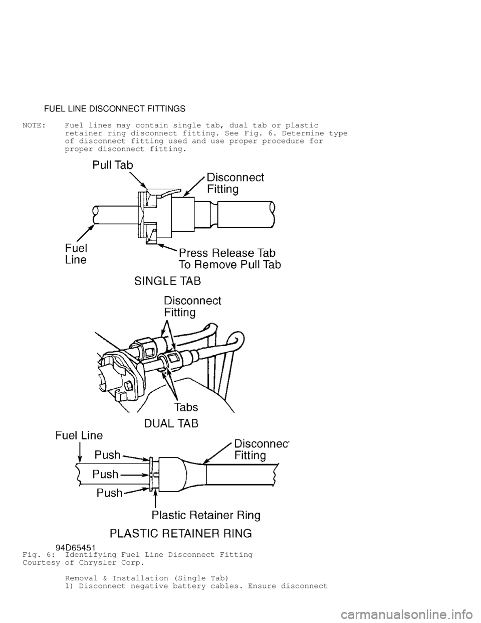
FUEL LINE DISCONNECT FITTINGS
NOTE: Fuel lines may contain single tab, dual tab or plastic
retainer ring disconnect fitting. See Fig. 6. Determine type
of disconnect fitting used and use proper procedure for
proper disconnect fitting.
Fig. 6: Identifying Fuel Line Disconnect Fitting
Courtesy of Chrysler Corp.
Removal & Installation (Single Tab)
1) Disconnect negative battery cables. Ensure disconnect
Page 929 of 1691
fitting and fuel lines are clean. Note location of release tab and
pull tab on disconnect fitting. See Fig. 6.
CAUTION: Release tab must be pressed downward before removing pull tab
or pull tab will be damaged.
2) Press release tab downward. Use screwdriver to pry pull
tab upward until pull tab separates from disconnect fitting. Remove
disconnect fitting from fuel line. Inspect components for damage. If
disconnect fitting is damaged, entire assembly must be replaced, as
only pull tab can be replaced.
3) To install, ensure fuel line and disconnect fitting are
clean. Lubricate fuel line and disconnect fitting with engine oil.
Install disconnect fitting on fuel line until disconnect fitting
bottoms on fuel line.
4) Install NEW pull tab until pull tab locks in disconnect
fitting. DO NOT reuse old pull tab. Pull on fuel line and disconnect
fitting to ensure components are properly locked together. Reconnect
negative battery cables. Start engine and check for leaks.
Removal & Installation (Dual Tab)
1) Disconnect negative battery cables. Ensure disconnect
fitting and fuel lines are clean. Note location of tabs on disconnect
fitting. See Fig. 6.
2) Squeeze both tabs against disconnect fitting. Pull
disconnect fitting from fuel line. The plastic retainer will remain on
the fuel system component being serviced. The "O" rings and spacer
will remain in the disconnect fitting.
3) Inspect components for damage. If disconnect fitting is
damaged, entire assembly must be replaced. The only component that may
be replaced is the plastic retainer. If plastic retainer must be
removed from fuel system component, carefully release the plastic
retainer from the fuel system component using 2 screwdrivers. Inspect
plastic retainer for cracks or damage. Replace plastic retainer if
defective.
4) To install, ensure fuel line and disconnect fitting are
clean. Lubricate fuel line and disconnect fitting with engine oil.
Install disconnect fitting on fuel line until click sound is heard.
5) Pull on fuel line and disconnect fitting to ensure
components are properly locked together. Reconnect negative battery
cables. Start engine and check for leaks.
Removal & Installation (Plastic Retainer Ring)
1) Disconnect negative battery cables. Ensure disconnect
fitting and fuel lines are clean. Note location of plastic retainer
ring on disconnect fitting. See Fig. 6.
NOTE: Plastic retainer ring must be pressed evenly into disconnect
fitting. If plastic retainer is not even, it will be
difficult to remove disconnect fitting from fuel line.
2) Firmly push disconnect fitting toward the fuel line while
pushing plastic retainer ring evenly into disconnect fitting. With
plastic retainer ring fully depressed, pull disconnect fitting from
fuel line.
3) Inspect components for damage. If disconnect fitting is
damaged, entire assembly must be replaced.
4) To install, ensure fuel line and disconnect fitting are
clean. Lubricate fuel line and disconnect fitting with engine oil.
Install disconnect fitting on fuel line until click sound is heard.
5) Pull on fuel line and disconnect fitting to ensure
components are properly locked together. Reconnect negative battery
cables. Start engine and check for leaks.
Page 932 of 1691
Removal
1) Raise and support vehicle. Disconnect negative battery
cables. Drain fuel tank. Remove fuel tank filler tube bolts from body.
Support fuel tank with transmission jack. Remove fuel tank straps and
heat shields (if equipped).
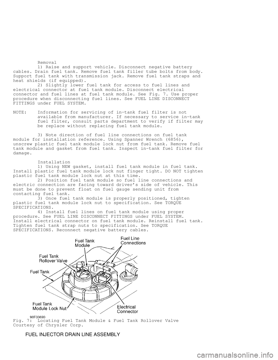
2) Slightly lower fuel tank for access to fuel lines and
electrical connector at fuel tank module. Disconnect electrical
connector and fuel lines at fuel tank module. See Fig. 7. Use proper
procedure when disconnecting fuel lines. See FUEL LINE DISCONNECT
FITTINGS under FUEL SYSTEM.
NOTE: Information for servicing of in-tank fuel filter is not
available from manufacturer. If necessary to service in-tank
fuel filter, consult parts department to verify if filter may
be replace without replacing fuel tank module.
3) Note direction of fuel line connections on fuel tank
module for installation reference. Using Spanner Wrench (6856),
unscrew plastic fuel tank module lock nut from fuel tank. Remove fuel
tank module and gasket from fuel tank. Inspect in-tank fuel filter for
damage.
Installation
1) Using NEW gasket, install fuel tank module in fuel tank.
Install plastic fuel tank module lock nut finger tight. DO NOT tighten
plastic fuel tank module lock nut at this time.
2) Position fuel tank module so fuel line connections and
electric connection are facing toward driver's side of vehicle. This
must be done to prevent float on fuel gauge sending unit from
contacting fuel tank.
3) Once fuel tank module is properly positioned, tighten
plastic fuel tank module lock nut to specification. See TORQUE
SPECIFICATIONS.
4) Install fuel lines on fuel tank module using proper
procedure. See FUEL LINE DISCONNECT FITTINGS under FUEL SYSTEM.
Install electrical connector on fuel tank module. Reinstall fuel tank.
Tighten fuel tank strap nuts to specification. See TORQUE
SPECIFICATIONS. Reconnect negative battery cables.
Fig. 7: Locating Fuel Tank Module & Fuel Tank Rollover Valve
Courtesy of Chrysler Corp.
FUEL INJECTOR DRAIN LINE ASSEMBLY
Page 933 of 1691
Removal
1) Remove nameplate located above rocker lever covers. Remove
fuel injector drain line-to-fuel injector banjo bolt and seal washer
from each fuel injector. Plug all fuel openings.
2) Remove fuel injector drain line assembly retaining clamp
at rear of intake manifold. Remove fuel injector drain line bolt with
seal washers at filter mounting head. See Fig. 3. Remove fuel injector
drain line assembly.
Installation
To install, reverse removal procedure using NEW seal washers.
Tighten bolts to specification. See TORQUE SPECIFICATIONS.
FUEL HEATER
Removal & Installation
Fuel heater is located in FUEL FILTER/WATER SEPARATOR &
WATER-IN-FUEL SENSOR. See FUEL FILTER/WATER SEPARATOR & WATER-IN-FUEL
SENSOR.
FUEL INJECTOR
Removal
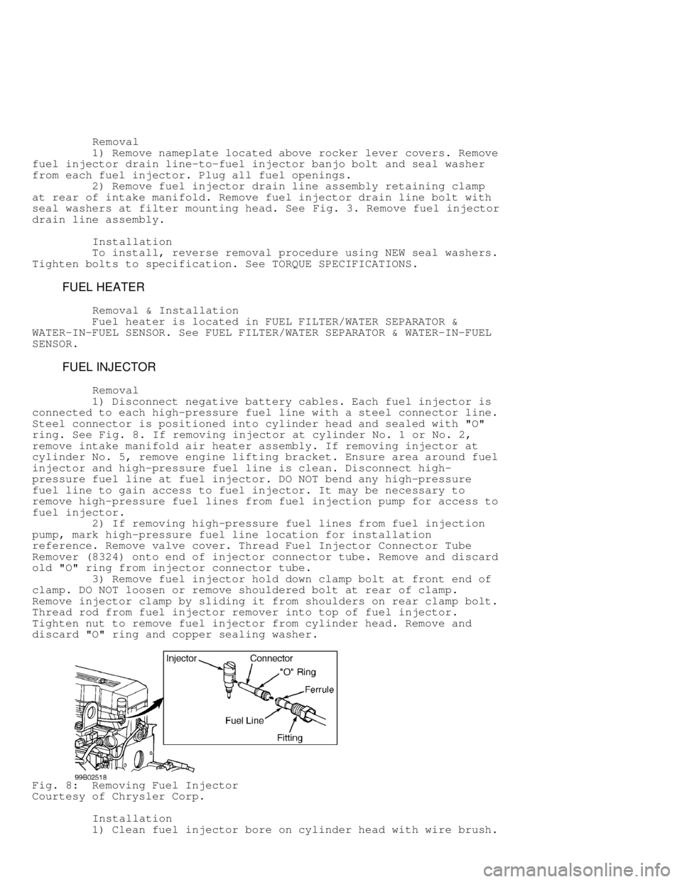
1) Disconnect negative battery cables. Each fuel injector is
connected to each high-pressure fuel line with a steel connector line.
Steel connector is positioned into cylinder head and sealed with "O"
ring. See Fig. 8. If removing injector at cylinder No. 1 or No. 2,
remove intake manifold air heater assembly. If removing injector at
cylinder No. 5, remove engine lifting bracket. Ensure area around fuel
injector and high-pressure fuel line is clean. Disconnect high-
pressure fuel line at fuel injector. DO NOT bend any high-pressure
fuel line to gain access to fuel injector. It may be necessary to
remove high-pressure fuel lines from fuel injection pump for access to
fuel injector.
2) If removing high-pressure fuel lines from fuel injection
pump, mark high-pressure fuel line location for installation
reference. Remove valve cover. Thread Fuel Injector Connector Tube
Remover (8324) onto end of injector connector tube. Remove and discard\
old "O" ring from injector connector tube.
3) Remove fuel injector hold down clamp bolt at front end of
clamp. DO NOT loosen or remove shouldered bolt at rear of clamp.
Remove injector clamp by sliding it from shoulders on rear clamp bolt.
Thread rod from fuel injector remover into top of fuel injector.
Tighten nut to remove fuel injector from cylinder head. Remove and
discard "O" ring and copper sealing washer.
Fig. 8: Removing Fuel Injector
Courtesy of Chrysler Corp.
Installation
1) Clean fuel injector bore on cylinder head with wire brush.