1999 DODGE RAM wiring
[x] Cancel search: wiringPage 396 of 1691

* PNP switch defective.
* PNP switch sense circuit open or shorted.
* PNP switch stuck.
* PCM defective.
NOTE: For component locations, see COMPONENT LOCATIONS. For
connector terminal identification, see CONNECTOR
IDENTIFICATION. For wiring diagram, see WIRING DIAGRAMS.
1) Turn ignition on. Using scan tool, read PNP switch state.
While observing scan tool, move gear selector between Park and
Reverse. If scan tool displays P/N and D/R, go to next step. If scan
tool does not display P/N and D/R, go to step 3).
2) Turn ignition off. Inspect wiring and connectors related
to PNP switch. Repair as necessary. Perform TEST VER-5A under
VERIFICATION TESTS. If wiring and connectors are okay, condition to
set FTC is not present at this time. Test is complete. Use freeze
frame data to determine conditions when FTC was set.
3) Turn ignition off. Disconnect PCM. Inspect connectors.
Clean or repair as necessary. Using an ohmmeter, check resistance
between ground and PNP switch sense circuit at PCM connector C1,
terminal No. 6 (Black/White wire). While observing ohmmeter, move gear\
selector from Park to Reverse and back to Park. If resistance switched
from less than 10 ohms to more than 10 ohms, replace PCM. Perform TEST
VER-5A under VERIFICATION TESTS. If resistance was less than 10 ohms
at all times, go to next step. If resistance was more than 10 ohms at
all times, go to step 5).
4) Disconnect PNP switch. Inspect connectors. Clean or repair
as necessary. Using an ohmmeter, check resistance between ground and
PNP switch sense circuit. If resistance is less than 5 ohms, repair
short to ground. Perform TEST VER-5A under VERIFICATION TESTS. If
resistance is 5 ohms or more, repair or replace stuck PNP switch.
Perform TEST VER-5A under VERIFICATION TESTS.
5) Using an ohmmeter, check resistance of PNP switch circuit
between PNP switch connector and PCM connector C1, terminal No. 6
(Black/White wire). If resistance is 5 ohms or more, repair open
circuit. Perform TEST VER-5A under VERIFICATION TESTS. If resistance
is less than 5 ohms, replace PNP switch. Perform TEST VER-5A under
VERIFICATION TESTS.
SYSTEM TESTS
NOTE: For component locations, See COMPONENT LOCATIONS. For
connector terminal identification, see CONNECTOR
IDENTIFICATION. For wiring diagram, see WIRING DIAGRAMS.
CHECKING SPEED CONTROL OPERATION
NOTE: Perform this test only if there are no DTCs.
1) Turn ignition on. Using scan tool, monitor S/C switch
inputs. Press S/C ON/OFF switch several times. If scan tool displays
speed control switch on and off, go to next step. If scan tool does
not display speed control switch on and off, go to NTC-3: SPEED
CONTROL ON/OFF SWITCH.
2) While observing scan tool, press RESUME/ACCEL switch
several times. If scan tool displays RESUME/ACCEL switch PRESSED and
RELEASED, go to next step. If scan tool does not display PRESSED and
RELEASED, go to NTC-4: SPEED CONTROL RESUME/ACCEL SWITCH.
3) While observing scan tool, press brake pedal several
times. If scan tool displays brake pedal PRESSED and RELEASED, go to
Page 402 of 1691

Fully depress brake pedal and rotate brake switch
counterclockwise approximately 30 degrees. Remove brake switch from
bracket. Depress lock tabs holding brake switch mounting bracket and
separate harness connector from brake switch.
Installation
1) Before installing brake switch, reset adjustable plunger
by pulling on plunger head until plunger reaches end of travel.
Connect harness connector to brake switch. Depress brake pedal and
insert brake switch into keyed hole in mounting bracket. Rotate brake
switch clockwise into locked position.
2) Gently pull back on brake pedal until pedal will go no
further. This causes the brake switch plunger to ratchet backward to
the correct position. No further adjustment is required.
SPEED CONTROL SERVO
Removal (Except Ram Van & Ram Wagon)
1) Disconnect negative battery cable. Disconnect electrical
connector and vacuum hose from servo. Using finger pressure only, push
servo cable connector from throttle body bellcrank pin. DO NOT pull
cable connector perpendicular to bellcrank.
2) Remove 2 servo cable mounting nuts. Pull servo cable
sleeve away from mounting bracket to expose cable retaining clip.
Remove retaining clip. Remove servo.
Removal (Ram Van & Ram Wagon)
1) Disconnect negative battery cable. Remove engine cover.
Remove air cleaner assembly. Using finger pressure only, push servo
cable connector from throttle body bellcrank pin. DO NOT pull cable
connector perpendicular to bellcrank.
2) Remove right headlight assembly. Disconnect vacuum hose
and electrical connector at servo. Remove 2 servo mounting bracket
bolts. Remove 2 servo cable mounting nuts. Pull servo cable sleeve
away from mounting bracket to expose cable retaining clip. Remove
retaining clip. Remove servo.
Installation (All Models)
With throttle in full open position, align hole in speed
control cable sleeve with hole in servo pin. Install retaining clip.
To complete installation, reverse removal procedure. Tighten mounting
bolts/nuts to 75 INCH lbs. (8.5 N.m).
SPEED CONTROL SWITCHES
Removal & Installation
Turn ignition off. Disconnect negative battery cable. Wait 2
minutes for air bag system to discharge reserve voltage. Remove 2
screws holding air bag assembly to steering column. Separate air bag
assembly from steering column and disconnect air bag, horn and speed
control switch connectors. Remove screws securing speed control switch
to air bag assembly. Separate speed control switch from air bag
assembly. To install, reverse removal procedure.
WIRING DIAGRAMS
Page 403 of 1691

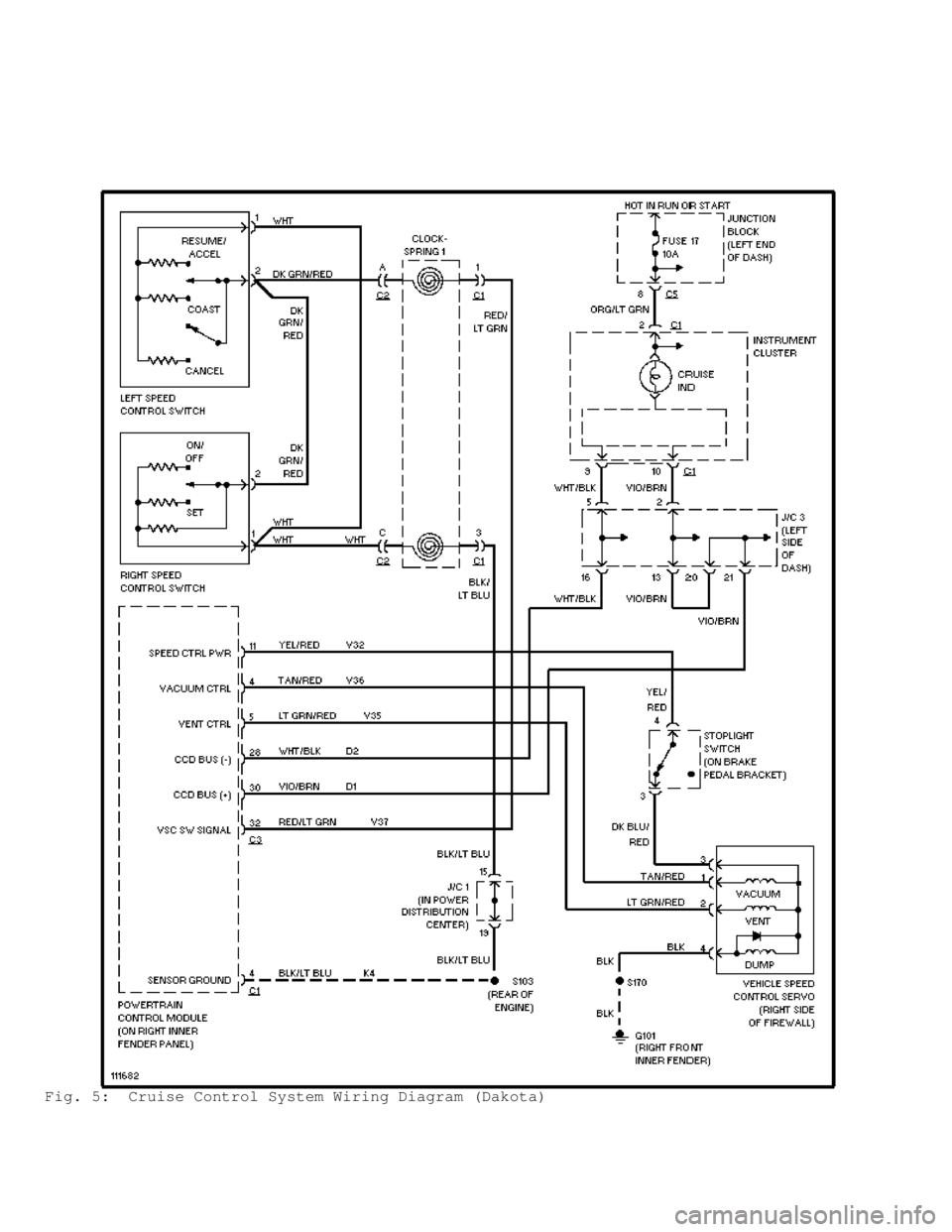
Fig. 5: Cruise Control System Wiring Diagram (Dakota)
Page 404 of 1691

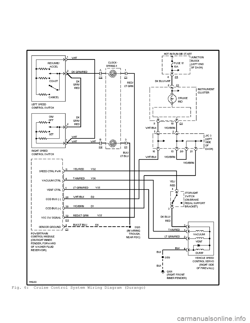
Fig. 6: Cruise Control System Wiring Diagram (Durango)
Page 405 of 1691

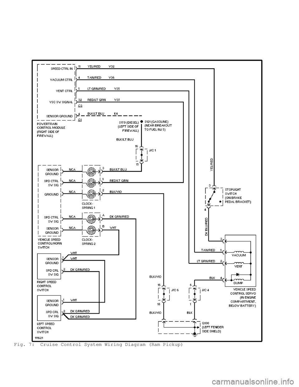
Fig. 7: Cruise Control System Wiring Diagram (Ram Pickup)
Page 406 of 1691

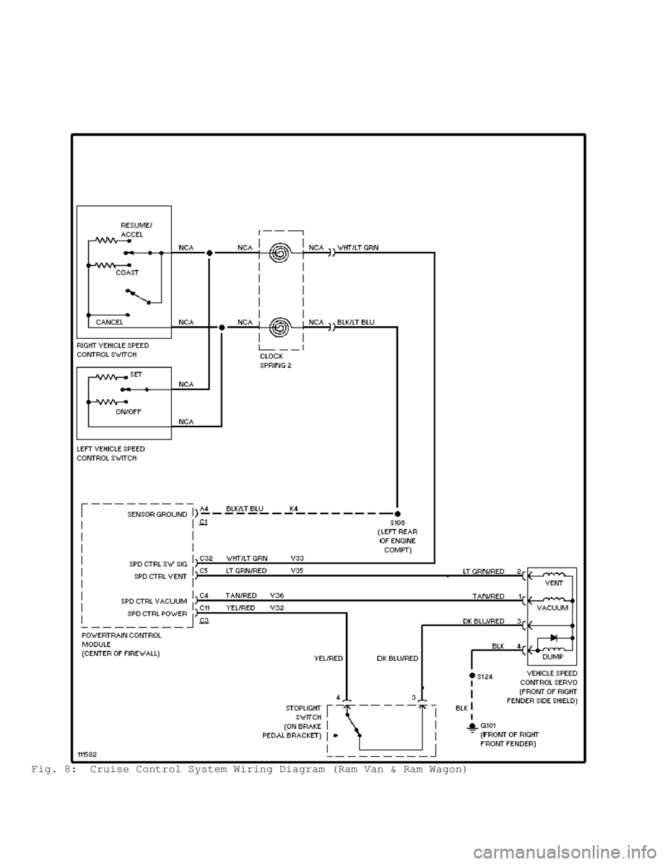
Fig. 8: Cruise Control System Wiring Diagram (Ram Van & Ram Wagon)
Page 410 of 1691

and fill if necessary.
STEERING KNUCKLES
Removal & Installation
1) Raise and support vehicle. Remove hub bearing and axle
shaft. Remove tie rod or drag link end from steering knuckle arm.
Remove ABS sensor harness and bracket from steering knuckle.
2) Remove cotter pin from upper ball stud nut. Remove upper
and lower ball stud nuts. Using a brass hammer, strike steering
knuckle to remove knuckle from axle tube yokes.
3) To install, reverse removal procedure. On 216 FBI axles,
tighten lower and upper ball stud nuts to specification. See TORQUE
SPECIFICATIONS table.
4) On 248 FBI axles, tighten lower ball stud nut to
specification. DO NOT install cotter pin at this time. Install and
tighten upper ball stud nut to specification. Retorque lower ball stud
nut to specification. See TORQUE SPECIFICATIONS table.
AXLE SHIFT MOTOR
Removal & Installation
1) Disconnect vacuum and wiring connector from shift housing.
Remove indicator switch, shift motor housing cover, gasket and shield
from housing.
2) To install, reverse removal procedure. Ensure shift fork
is correctly guided into shift collar groove. Tighten mounting bolts
to 96 INCH lbs. (11 N.m). Add 5 ounces (148 ml) of GL-5 gear lubrica\
nt
to shift motor housing through indicator switch mounting hole.
DIFFERENTIAL ASSEMBLY
NOTE: Differential assembly consists of differential case and
components mounted in axle housing. For differential assembly
servicing, see DIFFERENTIAL ASSEMBLY under OVERHAUL.
OVERHAUL
DIFFERENTIAL ASSEMBLY
Disassembly
1) Remove axle shafts from differential. See AXLE SHAFT & HUB
BEARING under REMOVAL & INSTALLATION.
2) Note identification marks on bearing caps and axle housing
for reassembly reference. Bearing caps must be installed in original
location. If marks are not present, place marks on bearing caps and
axle housing.
3) Remove bolts and bearing caps. Place Axle Housing Spreader
(W-129-B) on axle housing so dowel pins engage with locating holes.
See Fig. 1 . Install hold-down clamps. Finger tighten turnbuckle on
axle housing spreader.
4) Install pilot stud and dial indicator on axle housing.
Position dial indicator so stem is resting against opposite side of
axle housing, with pressure on stem.
CAUTION: DO NOT spread axle housing more than .020" (.50 mm), or axle
housing may be damaged.
5) Adjust dial indicator to zero. Tighten turnbuckle enough
to spread axle housing for differential case removal while noting
reading on dial indicator. Dial indicator reading should not exceed .
020" (.50 mm).
Page 472 of 1691

VEHICLE SPEED SENSORS
VENTS
VIBRATION DAMPERS
WHEEL ATTACHMENT HARDWARE
WHEEL SPEED SENSORS
WIRING HARNESSES AND CONNECTORS
YOKES AND SLIP YOKES
INTRODUCTION TO MOTORIST ASSURANCE PROGRAM (MAP)
OVERVIEW OF MOTORIST ASSURANCE PROGRAM
The Motorist Assurance Program is the consumer outreach
effort of the Automotive Maintenance and Repair Association, Inc.
(AMRA). Participation in the Motorist Assurance Program is drawn from
retailers, suppliers, independent repair facilities, vehicle
manufacturers and industry associations.
Our organization's mission is to strengthen the relationship
between the consumer and the auto repair industry. We produce
materials that give motorists the information and encouragement to
take greater responsibility for their vehicles-through proper,
manufacturer-recommended, maintenance. We encourage participating
service and repair shops (including franchisees and dealers) to adopt
(1) a Pledge of Assurance to their Customers and (2) the Motorist
Assurance Program Standards of Service. All participating service
providers have agreed to subscribe to this Pledge and to adhere to the
promulgated Standards of Service demonstrating to their customers that
they are serious about customer satisfaction.
These Standards of Service require that an inspection of the
vehicle's (problem) system be made and the results communicated to the\
customer according to industry standards. Given that the industry did
not have such standards, the Motorist Assurance Program successfully
promulgated industry inspection communication standards in 1994-95 for
the following systems: Exhaust, Brakes, ABS, Steering and Suspension,
Engine Maintenance and Performance, HVAC, and Electrical Systems.
Further, revisions to all of these inspection were recently published.
Further, revisions to all of these inspection communication standards
are continually republished. In addition to these, standards for Drive
Train and Transmissions have recently been promulgated. Participating
shops utilize these Uniform Inspection & Communication Standards as
part of the inspection process and for communicating their findings to
their customers.
The Motorist Assurance Program continues to work
cooperatively and proactively with government agencies and consumer
groups toward solutions that both benefit the customer and are
mutually acceptable to both regulators and industry. We maintain the
belief that industry must retain control over how we conduct our
business, and we must be viewed as part of the solution and not part
of the problem. Meetings with state and other government officials
(and their representatives), concerned with auto repair and/or
consumer protection, are conducted. Feedback from these sessions is
brought back to the association, and the program adjusted as needed.
To assure auto repair customers recourse if they were not
satisfied with a repair transaction, the Motorist Assurance Program
offers mediation and arbitration through MAP/BBB-CARE and other non-
profit organizations. MAP conducted pilot programs in twelve states
before announcing the program nationally in October, 1998. During the
pilots, participating repair shops demonstrated their adherence to the
Pledge and Standards and agreed to follow the UICS in communicating
the results of their inspection to their customers. To put some
"teeth" in the program, an accreditation requirement for shops was
initiated. The requirements are stringent, and a self-policing method