1999 DODGE NEON oil temperature
[x] Cancel search: oil temperaturePage 883 of 1200
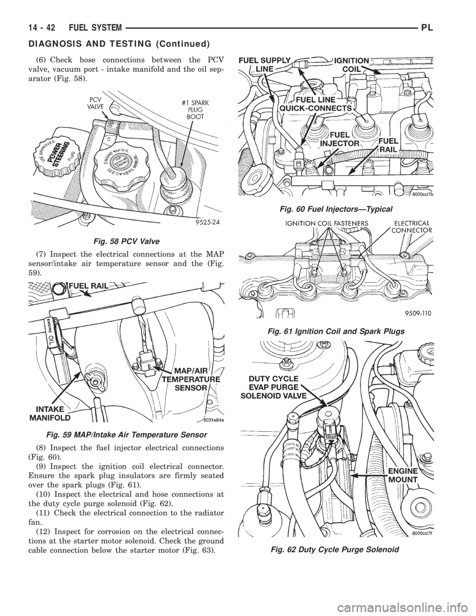
(6) Check hose connections between the PCV
valve, vacuum port - intake manifold and the oil sep-
arator (Fig. 58).
(7) Inspect the electrical connections at the MAP
sensor/intake air temperature sensor and the (Fig.
59).
(8) Inspect the fuel injector electrical connections
(Fig. 60).
(9) Inspect the ignition coil electrical connector.
Ensure the spark plug insulators are firmly seated
over the spark plugs (Fig. 61).
(10) Inspect the electrical and hose connections at
the duty cycle purge solenoid (Fig. 62).
(11) Check the electrical connection to the radiator
fan.
(12) Inspect for corrosion on the electrical connec-
tions at the starter motor solenoid. Check the ground
cable connection below the starter motor (Fig. 63).
Fig. 58 PCV Valve
Fig. 59 MAP/Intake Air Temperature Sensor
Fig. 60 Fuel InjectorsÐTypical
Fig. 61 Ignition Coil and Spark Plugs
Fig. 62 Duty Cycle Purge Solenoid
14 - 42 FUEL SYSTEMPL
DIAGNOSIS AND TESTING (Continued)
Page 911 of 1200
Rectangular pumping vanes in the shaft driven
rotor, move power steering fluid from the intake to
the cam ring pressure cavities of the power steering
pump. As the rotor begins to turn, centrifugal force
throws the vanes against the inside surface of the
cam ring to pickup residual oil. This oil is then forced
into the high pressure area. As more oil is picked up
by the vanes, the additional oil is forced into the cav-
ities of the thrust plate through two crossover holes
in the cam ring and pressure plate. The crossover
holes empty into the high pressure area between the
pressure plate and the housing end cover.
As the high pressure area is filled, oil flows under
the vanes in the rotor slots, forcing the vanes to fol-
low the inside surface of the cam ring. As the vanes
reach the restricted area of the cam ring, oil is forced
out from between the vanes. When excess oil flow is
generated during high-speed operation, a regulated
amount of oil returns to the pump intake side
through a flow control valve. The flow control valve
reduces the power required to drive the pump and
holds down temperature build-up.
When steering conditions exceed maximum pres-
sure requirements, such as when the wheels are
turned against the stops. The pressure built up in
the steering gear exerts pressure on the spring end of
the flow control valve. The high pressure lifts the
relief valve ball from its seat and allows oil to flow
through a trigger orifice located in the outlet fitting.
This reduces pressure on the spring end of the flow
control valve which then opens and allows the oil to
return to the intake side of the pump. This action
limits maximum pressure output of the pump to a
safe level.
Under normal power steering pump operating con-
ditions, pressure requirements of the pump are below
maximum, causing the pressure relief valve to
remain closed.
DIAGNOSIS AND TESTING
POWER STEERING SYSTEM TEST PROCEDURE
The following procedure can be used to test the
operation of the power steering system on the vehi-
cle. This test will provide the flow rate of the power
steering pump along with the maximum relief pres-
sure. This test is to be performed any time a power
steering system problem is present to determine if
the power steering pump or power steering gear is
not functioning properly. The following pressure and
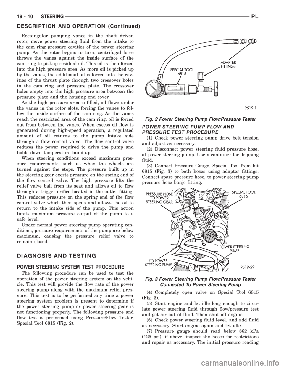
flow test is performed using Pressure/Flow Tester,
Special Tool 6815 (Fig. 2).
POWER STEERING PUMP FLOW AND
PRESSURE TEST PROCEDURE
(1) Check power steering pump drive belt tension
and adjust as necessary.
(2) Disconnect power steering fluid pressure hose,
at power steering pump. Use a container for dripping
fluid.
(3) Connect Pressure Gauge, Special Tool from kit
6815 (Fig. 3) to both hoses using adapter fittings.
Connect spare pressure hose, to power steering pump
pressure hose banjo fitting.
(4) Completely open valve on Special Tool 6815
(Fig. 3).
(5) Start engine and let idle long enough to circu-
late power steering fluid through flow/pressure test
and get air out of fluid. Then shut off engine.
(6) Check power steering fluid level, and add fluid
as necessary. Start engine again and let idle.
(7) Pressure gauge should read below 862 kPa
(125 psi), if above, inspect the hoses for restrictions
and repair as necessary. The initial pressure reading
Fig. 2 Power Steering Pump Flow/Pressure Tester
Fig. 3 Power Steering Pump Flow/Pressure Tester
Connected To Power Steering Pump
19 - 10 STEERINGPL
DESCRIPTION AND OPERATION (Continued)
Page 984 of 1200
NOTE: Transaxle operation requirements are differ-
ent for each vehicle and engine combination. Some
internal parts will be different to provide for this.
Therefore, when replacing parts, refer to the seven
digit part number stamped on rear of the transaxle
oil pan flange.
Within this transaxle, there are three primary
areas:
(1) Main center line plus valve body.
(2) Transfer shaft center line (includes governor
and parking sprag).
(3) Differential center line.
Center distances between the main rotating parts
in these three areas are held precise to maintain a
low noise level.
The torque converter, transaxle area, and differen-
tial are housed in an integral aluminum die casting.
The differential oil sump is common with the
transaxle sump. Separate filling of the differen-
tial is NOT necessary.
The torque converter is attached to the crankshaft
through a flexible driving plate. Cooling of the con-
verter is accomplished by circulating the transaxle
fluid through a remote cooler. There are two types of
coolers used. An oil-to-water type cooler located in
the radiator side tank and/or an oil-to-air heat
exchanger. The torque converter assembly is a sealed
unit that cannot be disassembled.
The transaxle fluid is filtered by an internal filter
attached to the lower side of the valve body assembly.
Engine torque is transmitted to the torque con-
verter and then through the input shaft to multiple-
disc clutches in the transaxle. The power flow
depends on the application of the clutches and bands.
Refer to Elements in Use Chart in Diagnosis and
Tests section.
The transaxle consists of:
²Two multiple-disc clutches
²An overrunning clutch
²Two servos
²A hydraulic accumulator
²Two bands
²Two planetary gear sets
This provides three forward ratios and a reverse
ratio. The common sun gear of the planetary gear
sets is connected to the front clutch by a driving
shell. The driving shell is splined to the sun gear and
front clutch retainer. The hydraulic system consists
of an oil pump and a single valve body which con-
tains all of the valves except the governor valves.
The transaxle sump and differential sump are both
vented through the dipstick. Output torque from the
main center line is delivered through helical gears to
the transfer shaft. This gear set is a factor in the
transaxle final drive (axle) ratio. The shaft also car-
ries the governor and parking sprag. An integral heli-cal gear on the transfer shaft drives the differential
ring gear. The final drive gearing is completed with
one of two gear ratios; 2.98 or 3.19 depending on
model and application.
FLUID LEVEL AND CONDITION
NOTE: The transmission and differential sump have
a common oil sump with a communicating opening
between the two.
The torque converter fills in both the P (Park) and
N (Neutral) positions. Place the selector lever in P
(Park) to be sure that the fluid level check is accu-
rate.The engine should be running at idle
speed for at least one minute, with the vehicle
on level ground. This will ensure complete oil
level stabilization between differential and
transmission.The fluid should be at normal operat-
ing temperature (approximately 82É C. or 180É F.).
The fluid level is correct if it is in the HOT region
(cross-hatched area) on the dipstick.
Low fluid level can cause a variety of conditions,
because it allows the pump to take in air along with
the fluid. As in any hydraulic system, air bubbles
make the fluid spongy therefore, pressures will be
low and will build up slowly.
Improper filling also can raise the fluid level too
high. When the transaxle has too much fluid, the
gears churn up foam and cause the same conditions
that occur with a low fluid level.
In either case, the air bubbles can cause overheat-
ing, fluid oxidation, and varnishing. This can inter-
fere with normal valve, clutch, and servo operation.
Foaming also can result in fluid escaping from the
transaxle dipstick, where it may be mistaken for a
leak.
Along with fluid level, it is important to check the
condition of the fluid. When the fluid smells burned,
or is contaminated with metal or friction material
particles, a complete transaxle overhaul is needed.
Be sure to examine the fluid on the dipstick closely.
If there is any doubt about its condition, drain out a
sample for a double check.
SELECTION OF LUBRICANT
It is important that the proper lubricant be used in
these transmissions. Mopar ATF PLUS 3 (Automatic
Transmission Fluid- type 7176) should be used to aid
in ensuring optimum transmission performance. It is
important that the transmission fluid be maintained
at the prescribed level using the recommended fluids.
SPECIAL ADDITIVES
Chrysler Corporation does not recommend the
addition of any fluids to the transmission, other than
that fluid listed above. An exception to this policy is
PLTRANSAXLE 21 - 41
GENERAL INFORMATION (Continued)
Page 999 of 1200
position should not be possible when the ignition
switch is in the LOCK or the ACCESSORY position.
(3) If the interlock system, operates in any way
other than as described above, repair of the interlock
system is required. See Adjustment and Repair pro-
cedures in this section for the required procedures.
SERVICE PROCEDURES
FLUID AND FILTER CHANGE
When the factory fill fluid is changed, only fluids
labeled MOPARtATF PLUS 3 (Automatic Transmis-
sion fluid) Type 7176 should be used.
If the transaxle is disassembled for any reason, the
fluid and filter should be changed.
30,000 MILE TRANSAXLE OIL CHANGE
When a vehicle attains 30,000 miles on its odome-
ter it is recommended that the transaxle oil be
changed. To change the oil, use the procedure that
follows:
It is recommended that a transaxle fluid exchanger
(ATF 2000+ or equivalent) be used to replace the
used fluid in the transaxle. If a fluid exchanger is not
available use a fluid suction pump (Vaculayor equiv-
alent) to draw the fluid out of the dipstick tube. If a
fluid suction pump is not available remove the oil
pan and drain the fluid.
CAUTION: Chrysler Corporation does not recom-
mend using any fluid exchanger that introduces
additives into the transaxle.
TRANSAXLE FLUID EXCHANGER METHOD
(1) To perform the transaxle fluid exchange, the
transaxle must be at operating temperature. Drive
the vehicle till it reaches full operating temperature.
(2) Verify that the fill tank on the transaxle fluid
exchanger (ATF 2000+ or equivalent) is clean and
dry.
(3) Fill the tank to the recommended fill capacity
with Mopar ATF Plus 3 Type 7176.
(4) Hookup the vehicle to the machine following
the manufacturers instructions. Perform the
exchange procedure following the instructions pro-
vided with the machine.
(5) Once machine has completed the fluid
exchange. Check the fluid level and condition and fill
to proper level with Mopar ATF Plus 3 Type 7176.
NOTE: Verify that the transaxle cooler lines are
tightened to proper specifications. Cooler line
torque specification is 2 N²m (18 in. lbs.).DIPSTICK TUBE FLUID SUCTION METHOD
(1) When performing the fluid suction method,
make sure the transaxle is at full operating temper-
ature.
(2) To perform the dipstick tube fluid suction
method, use a suitable fluid suction device (Vaculay
or equivalent).
(3) Insert the fluid suction line into the dipstick
tube.
NOTE: Verify that the suction line is inserted to the
lowest point of the transaxle oil pan. This will
ensure complete evacuation of the fluid in the pan.
(4) Follow the manufacturers recommended proce-
dure and evacuate the fluid from the transaxle.
(5) Remove the suction line from the dipstick tube.
(6) Add 4 Quarts of Mopar ATF Plus 3 Type 7176
transaxle fluid.
(7) Start the engine and allow it to idle for a min-
imum of one minute. With the parking brake applied,
press your foot on the service brake and cycle the
transaxle from park to all gear positions ending in
neutral or park.
(8) Check the transaxle fluid level and add an
appropriate amount to bring the transaxle fluid level
to 3mm (1/8 in.) below the ADD mark on the dip-
stick.
(9) Recheck the fluid level after the transaxle is at
normal operating temperature. The level should be in
the HOT range.
TRANSAXLE OIL PAN DROP METHOD
This procedure involves removing the transaxle oil
pan to drain the transaxle fluid.
(1) Bring the vehicle up to normal operating tem-
perature. Drive the vehicle a minimum of 10 miles.
(2) Raise the vehicle on the hoist.
(3) Loosen the transaxle oil pan and drain the
fluid into a suitable container.
(4) Remove the pan and clean all sealant from the
pan and transaxle mating surfaces. Clean the mag-
net and the inside of the pan.
(5) Apply a 1/8 inch bead of Mopar RTV Sealant to
the mounting flange of the transaxle oil pan. Apply
RTV Sealant to the underside of the attaching bolts.
Attach the oil pan to the transaxle. Tighten the bolts
to 19 N²m (165 in. lbs.).
(6) Lower the vehicle and add 4 Quarts of Mopar
ATF Plus 3 Type 7176 transaxle fluid.
(7) Start the engine and allow it to idle for a min-
imum of one minute. With the parking brake applied,
press your foot on the service brake and cycle the
transaxle from park to all gear positions ending in
neutral or park.
(8) Check the transaxle fluid level and add an
appropriate amount to bring the transaxle fluid level
21 - 56 TRANSAXLEPL
DIAGNOSIS AND TESTING (Continued)
Page 1000 of 1200
to 3mm (1/8 in.) below the ADD mark on the dip-
stick.
(9) Recheck the fluid level after the transaxle is at
normal operating temperature. The level should be in
the HOT range. Drive the vehicle a minimum of 10
miles.
(10) Raise the vehicle on the hoist.
(11) Check for leaks around the transaxle oil pan
sealing surfaces.
(12) Recheck the fluid level. The level should be in
the HOT range.
SEVERE USAGE SERVICE
If the vehicle exhibits any of the following symp-
toms, it is recommended that the transaxle oil and
filter be replaced.
²Transaxle oil discolored
²Transaxle oil has high mileage
²Oil feels grimy when rubbed between fingertips
²Poor shift quality
²Delayed gear engagement
²Vehicle shudder between shifts
TRANSAXLE OIL AND FILTER REPLACEMENT
This procedure involves changing the transaxle
fluid and filter, driving the vehicle for 10 miles and
changing the transaxle fluid a second time.
(1) Bring the vehicle up to normal operating tem-
perature. Drive the vehicle a minimum of 10 miles.
(2) Raise the vehicle on the hoist.
(3) Loosen the transaxle oil pan and drain the
fluid into a suitable container.
(4) Remove the pan and clean all sealant from the
pan and transaxle mating surfaces. Clean the mag-
net and the inside of the pan.
(5) Separate the filter and O-ring from the valve
body. Inspect the O-ring for cuts or improper instal-
lation. This could lead to delayed garage shifts.
(6) Install a new filter. Replace the O-ring as nec-
essary.
(7) Apply a 1/8 inch bead of Mopar RTV Sealant to
the mounting flange of the transaxle oil pan. Apply
RTV Sealant to the underside of the attaching bolts.
Attach the oil pan to the transaxle. Tighten the bolts
to 19 N²m (165 in. lbs.).
(8) Lower the vehicle and add 4 Quarts of Mopar
ATF Plus 3 Type 7176 transaxle fluid.
(9) Start the engine and allow it to idle for a min-
imum of one minute. With the parking brake applied,
press your foot on the service brake and cycle the
transaxle from park to all gear positions ending in
neutral or park.
(10) Check the transaxle fluid level and add an
appropriate amount to bring the transaxle fluid level
to 3mm (1/8 in.) below the ADD mark on the dip-
stick.(11) Recheck the fluid level after the transaxle is
at normal operating temperature. The level should be
in the HOT range. Drive the vehicle a minimum of
10 miles.
(12) Raise the vehicle on the hoist.
(13) Remove the pan and clean all sealant from
the pan and transaxle mating surfaces. Clean the
magnet and the inside of the pan.
(14) Separate the filter from the valve body to
allow additional fluid to drain from the transaxle.
Inspect the filter O-ring for any damage and replace
as necessary.
(15) After the transaxle has stopped draining,
reinstall the filter and O-ring.
(16) Apply a 1/8 inch bead of Mopar RTV Sealant
to the mounting flange of the transaxle oil pan.
Apply RTV Sealant to the underside of the attaching
bolts. Attach the oil pan to the transaxle. Tighten the
bolts to 19 N²m (165 in. lbs.).
(17) Lower the vehicle and add 4 Quarts of Mopar
ATF Plus 3 Type 7176 transaxle fluid.
(18) Start the engine and allow it to idle for a min-
imum of one minute. With the parking brake applied,
press your foot on the service brake and cycle the
transaxle from park to all gear positions ending in
neutral or park.
(19) Check the transaxle fluid level and add an
appropriate amount to bring the transaxle fluid level
to 3mm (1/8 in.) below the ADD mark on the dip-
stick.
(20) Recheck the fluid level after the transaxle is
at normal operating temperature. The level should be
in the HOT range.
FLUID DRAIN AND REFILL
(1) Raise vehicle on a hoist (See Group 0, Lubrica-
tion). Place a drain container, with a large opening,
under transaxle oil pan.
(2) Loosen pan bolts and tap the pan at one corner
to break it loose allowing fluid to drain, then remove
the oil pan.
(3) Install a new filter and gasket on bottom of the
valve body and tighten retaining screws to 5 N´m (40
inch-pounds).
(4) Clean the oil pan and magnet. Reinstall pan
using new sealant. Tighten oil pan bolts to 19 N´m
(165 in. lbs.).
(5) Pour four quarts of Mopar ATF PLUS 3 (Auto-
matic Transmission Fluid) type 7176 into the tran-
saxle filler tube.
(6) Start engine and allow to idle for at least one
minute. Then, with parking and service brakes
applied, move selector lever momentarily to each
position, ending in the PARK or NEUTRAL position.
(7) Add sufficient fluid to bring level to 1/8 inch
below the ADD mark.
PLTRANSAXLE 21 - 57
SERVICE PROCEDURES (Continued)
Page 1001 of 1200
(8) Recheck fluid level after transaxle is at normal
operating temperature. The level should be in the
HOT region.
ALUMINUM THREAD REPAIR
Damaged or worn threads in the aluminum tran-
saxle case and valve body can be repaired by the use
of Heli-Coils. This repair consists of drilling out the
worn-out or damaged threads. Then tap the hole with
a Heli-Coil tap, and install a Heli-Coil insert into the
hole. This brings the hole back to its original thread
size.
Heli-Coil tools and inserts are readily available
from most automotive parts suppliers.
FLUSHING COOLERS AND TUBES
When a transaxle failure has contaminated the
fluid, the oil cooler(s) must be flushed. The cooler
bypass valve in the transaxle must be replaced also.
The torque converter must also be replaced with an
exchange unit. This will ensure that metal particles
or sludged oil are not later transferred back into the
reconditioned (or replaced) transaxle.
The recommended procedure for flushing the cool-
ers and tubes is to use Tool 6906A Cooler Flusher.
WARNING: WEAR PROTECTIVE EYEWEAR THAT
MEETS THE REQUIREMENTS OF OSHA AND ANSI
Z87.1±1968. WEAR STANDARD INDUSTRIAL RUB-
BER GLOVES.
KEEP LIGHTED CIGARETTES, SPARKS, FLAMES,
AND OTHER IGNITION SOURCES AWAY FROM THE
AREA TO PREVENT THE IGNITION OF COMBUSTI-
BLE LIQUIDS AND GASES. KEEP A CLASS (B) FIRE
EXTINGUISHER IN THE AREA WHERE THE
FLUSHER WILL BE USED.
KEEP THE AREA WELL VENTILATED.
DO NOT LET FLUSHING SOLVENT COME IN CON-
TACT WITH YOUR EYES OR SKIN: IF EYE CONTAM-
INATION OCCURS, FLUSH EYES WITH WATER FOR
15 TO 20 SECONDS. REMOVE CONTAMINATED
CLOTHING AND WASH AFFECTED SKIN WITH
SOAP AND WATER. SEEK MEDICAL ATTENTION.
COOLER FLUSH USING TOOL 6906A
(1) Remove cover plate filler plug on Tool 6906A.
Fill reservoir 1/2 to 3/4 full of fresh flushing solution.
Flushing solvents are petroleum based solutions gen-
erally used to clean automatic transmission compo-
nents.DO NOTuse solvents containing acids, water,
gasoline, or any other corrosive liquids.
(2) Reinstall filler plug on Tool 6906A.
(3) Verify pump power switch is turned OFF. Con-
nect red alligator clip to positive (+) battery post.
Connect black (-) alligator clip to a good ground.
(4) Disconnect the cooler lines at the transmission.NOTE: When flushing transmission cooler and
lines, ALWAYS reverse flush.
(5) Connect the BLUE pressure line to the OUT-
LET (From) cooler line.
(6) Connect the CLEAR return line to the INLET
(To) cooler line
(7) Turn pump ON for two to three minutes to
flush cooler(s) and lines. Monitor pressure readings
and clear return lines. Pressure readings should sta-
bilize below 20 psi. for vehicles equipped with a sin-
gle cooler and 30 psi. for vehicles equipped with dual
coolers. If flow is intermittent or exceeds these pres-
sures, replace cooler.
(8) Turn pump OFF.
(9) Disconnect CLEAR suction line from reservoir
at cover plate. Disconnect CLEAR return line at
cover plate, and place it in a drain pan.
(10) Turn pump ON for 30 seconds to purge flush-
ing solution from cooler and lines. Turn pump OFF.
(11) Place CLEAR suction line into a one quart
container of Mopar ATF Plus 3ttype 7176 automatic
transmission fluid.
(12) Turn pump ON until all transmission fluid is
removed from the one quart container and lines. This
purges any residual cleaning solvent from the trans-
mission cooler and lines. Turn pump OFF.
(13) Disconnect alligator clips from battery. Recon-
nect flusher lines to cover plate, and remove flushing
adapters from cooler lines.
OIL PUMP VOLUME CHECK
After the new or repaired transmission has been
installed, fill to the proper level with Mopar ATF
PLUS 3 (Type 7176) automatic transmission fluid.
The volume should be checked using the following
procedure:
(1) Disconnect theFrom coolerline at the trans-
mission and place a collecting container under the
disconnected line.
CAUTION: With the fluid set at the proper level,
fluid collection should not exceed (1) quart or inter-
nal damage to the transmission may occur.
(2) Run the engineat curb idle speed, with the
shift selector in neutral.
(3) If fluid flow is intermittent or it takes more
than 20 seconds to collect one quart of ATF, discon-
nect theTo Coolerline at the transaxle.
(4) Refill the transaxle to proper level and recheck
pump volume.
(5) If flow is found to be within acceptable limits,
replace the cooler. Then fill transmission to the
proper level, using Mopar ATF PLUS 3 (Type 7176)
automatic transmission fluid.
21 - 58 TRANSAXLEPL
SERVICE PROCEDURES (Continued)
Page 1134 of 1200
HEATING AND AIR CONDITIONING
CONTENTS
page page
GENERAL INFORMATION
INTRODUCTION......................... 2
SAFETY PRECAUTIONS AND WARNINGS..... 2
DESCRIPTION AND OPERATION
A/C REFRIGERANT LINES................. 3
BLOWER MOTOR RESISTOR............... 3
COMPRESSOR FRONT SHAFT SEAL......... 4
COMPRESSOR.......................... 4
CONDENSATION DRAIN TUBE.............. 4
ENGINE COOLING SSTEM
REQUIREMENTS....................... 4
EVAPORATOR PROBE..................... 4
HANDLING TUBING AND FITTINGS.......... 4
HIGH PRESSURE CUT OUT SWITCH......... 5
LOW PRESSURE CUT OFF SWITCH......... 5
SIDE WINDOW DEMISTERS............... 5
SYSTEM AIRFLOW....................... 5
SYSTEM OIL LEVEL...................... 6
VACUUM CONTROL SYSTEM............... 6
DIAGNOSIS AND TESTING
A/C PERFORMANCE TEST................. 6
BLOWER MOTOR ELECTRICAL DIAGNOSIS . . . 8
BLOWER MOTOR VIBRATION
AND/OR NOISE DIAGNOSIS.............. 8
COMPRESSOR NOISE DIAGNOSIS.......... 7
EVAPORATOR PROBE TEST................ 8
EXPANSION VALVE....................... 7
HEATER PERFORMANCE TEST............. 8
LOW PRESSURE CUT-OFF SWITCH......... 11
SYSTEM CHARGE LEVEL TEST............ 11
VACUUM CONTROL SYSTEM.............. 12
SERVICE PROCEDURES
CHARGING A/C SYSTEM................. 14
EVACUATING REFRIGERANT SYSTEM....... 15R-134a REFRIGERANT................... 16
SERVICING REFRIGERANT OIL LEVEL...... 17
SYSTEM LEAK CHECKING................ 17
REMOVAL AND INSTALLATION
A/C FILTER/DRIER...................... 23
A/C SERVICE PORT VALVE CORES......... 18
BLOWER MOTOR AND WHEEL ASSEMBLY . . . 18
BLOWER MOTOR RESISTOR.............. 18
BLOWER MOTOR WHEEL................ 19
COMPRESSOR CLUTCH/COIL ASSEMBLY.... 19
COMPRESSOR......................... 19
CONDENSATION DRAIN TUBE............ 21
CONDENSER........................... 21
DISCHARGE LINE....................... 21
EVAPORATOR PROBE.................... 22
EVAPORATOR.......................... 21
EXPANSION VALVE...................... 23
HEATER CORE......................... 24
HEATER HOSES........................ 24
HIGH PRESSURE CUT OUT SWITCH........ 23
HIGH PRESSURE RELIEF VALVE........... 24
LIQUID LINE........................... 25
LOW PRESSURE CUT OFF SWITCH........ 25
MODE CONTROL CABLE................. 25
RECIRCULATION DOOR ACTUATOR........ 26
SUCTION LINE......................... 27
TEMPERATURE CONTROL CABLE.......... 27
UNIT HOUSING......................... 27
DISASSEMBLY AND ASSEMBLY
AIR DISTRIBUTION MODULE ±
RECONDITION........................ 28
ADJUSTMENTS
MODE CONTROL CABLE................. 30
TEMPERATURE CONTROL CABLE.......... 30
PLHEATING AND AIR CONDITIONING 24 - 1
Page 1137 of 1200
COMPRESSOR
The compressor used on this vehicle is a Nippon-
denso 10PA17 R-134a. This compressor uses an alu-
minum swash plate, teflon coated pistons and
aluminum sleeved cylinder walls.
CAUTION: A 10PA17 R-12 compressor looks identi-
cal to a 10PA17 R-134a and will bolt up to the vehi-
cle. The 10PA17 R-12 compressor must not be used
on this system. It is extremely important that a
10PA17 R-134a compressor is identified prior to
using compressor in question. Check tag located
on compressor for model number.
NOISE
Excessive noise that occurs when the air condition-
ing is being used may be caused by:
²Loose bolts
²Mounting brackets
²Loose compressor clutch
²Excessive high refrigerant operating pressure
Verify the following before compressor repair is
performed:
(1) Compressor drive belt condition
(2) Proper refrigerant charge
(3) Thermal expansion valve (TXV) operating cor-
rectly
(4) Head pressure is normal
COMPRESSOR FRONT SHAFT SEAL
The compressor front shaft seal is not serviceable.
If a leak is detected at the shaft seal, the compressor
must be replaced as a unit.
CONDENSATION DRAIN TUBE
Condensation that accumulates in the evaporator
housing is drained from a tube through the dash and
on to the ground. This tube must be kept open to
prevent condensate water from collecting in the bot-
tom of the housing.
The tapered end of the drain tube is designed to
keep contaminants from entering the heater A/C unit
housing. If the tube is pinched or blocked, condensate
cannot drain, causing water to back up and spill into
the passenger compartment. It is normal to see con-
densate drainage below the vehicle. If the tube is
damaged, it should be replaced.
ENGINE COOLING SYSTEM REQUIREMENTS
To maintain ample temperature levels from the
heating-A/C system, the cooling system must be in
proper working order. Refer to Group 0, Lubrication
and Maintenance or Group 7, Cooling System of this
manual.
The use of a bug screen is not recommended. Any
obstructions forward of the condenser can reduce the
effectiveness of the air conditioning system.
EVAPORATOR PROBE
The evaporator probe can be replaced without hav-
ing to remove the unit housing from the vehicle.
The evaporator probe is located in the unit housing
and placed in the evaporator fins. The probe prevents
evaporator freeze-up. This is done by cycling the com-
pressor clutch OFF when evaporator temperature
drops below freeze point. It cycles ON when the
evaporator temperature rises above freeze point. The
evaporator probe uses a thermistor probe in a capil-
lary tube. The tube is inserted between the evapora-
tor fins in the heater-A/C unit housing.
HANDLING TUBING AND FITTINGS
Kinks in the refrigerant tubing or sharp bends in
the refrigerant hose lines will greatly reduce the
capacity of the entire system. High pressures are pro-
duced in the system when it is operating. Extreme
care must be exercised to make sure that all connec-
tions are pressure tight. Dirt and moisture can enter
the system when it is opened for repair or replace-
ment of lines or components. The refrigerant oil will
absorb moisture readily out of the air. This moisture
will convert into acids within a closed system.
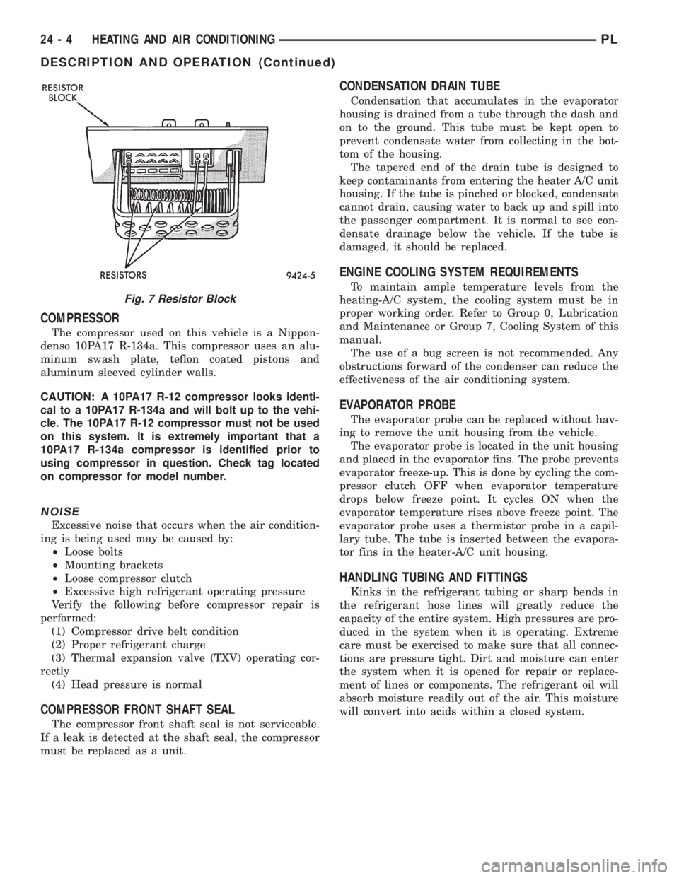
Fig. 7 Resistor Block
24 - 4 HEATING AND AIR CONDITIONINGPL
DESCRIPTION AND OPERATION (Continued)