1999 DODGE NEON warning light
[x] Cancel search: warning lightPage 174 of 1200
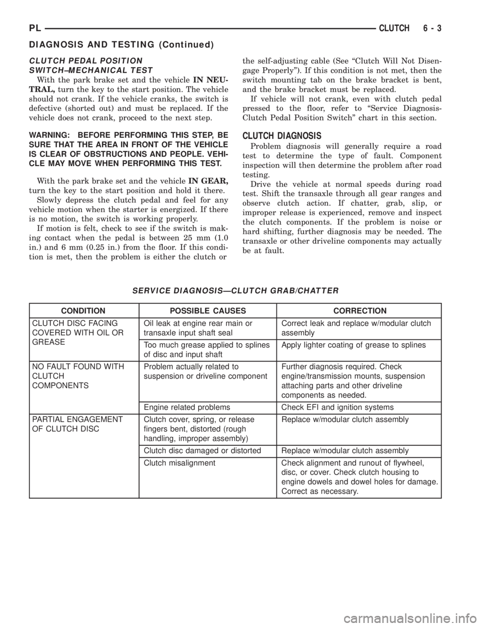
CLUTCH PEDAL POSITION
SWITCH±MECHANICAL TEST
With the park brake set and the vehicleIN NEU-
TRAL,turn the key to the start position. The vehicle
should not crank. If the vehicle cranks, the switch is
defective (shorted out) and must be replaced. If the
vehicle does not crank, proceed to the next step.
WARNING: BEFORE PERFORMING THIS STEP, BE
SURE THAT THE AREA IN FRONT OF THE VEHICLE
IS CLEAR OF OBSTRUCTIONS AND PEOPLE. VEHI-
CLE MAY MOVE WHEN PERFORMING THIS TEST.
With the park brake set and the vehicleIN GEAR,
turn the key to the start position and hold it there.
Slowly depress the clutch pedal and feel for any
vehicle motion when the starter is energized. If there
is no motion, the switch is working properly.
If motion is felt, check to see if the switch is mak-
ing contact when the pedal is between 25 mm (1.0
in.) and 6 mm (0.25 in.) from the floor. If this condi-
tion is met, then the problem is either the clutch orthe self-adjusting cable (See ªClutch Will Not Disen-
gage Properlyº). If this condition is not met, then the
switch mounting tab on the brake bracket is bent,
and the brake bracket must be replaced.
If vehicle will not crank, even with clutch pedal
pressed to the floor, refer to ªService Diagnosis-
Clutch Pedal Position Switchº chart in this section.
CLUTCH DIAGNOSIS
Problem diagnosis will generally require a road
test to determine the type of fault. Component
inspection will then determine the problem after road
testing.
Drive the vehicle at normal speeds during road
test. Shift the transaxle through all gear ranges and
observe clutch action. If chatter, grab, slip, or
improper release is experienced, remove and inspect
the clutch components. If the problem is noise or
hard shifting, further diagnosis may be needed. The
transaxle or other driveline components may actually
be at fault.
SERVICE DIAGNOSISÐCLUTCH GRAB/CHATTER
CONDITION POSSIBLE CAUSES CORRECTION
CLUTCH DISC FACING
COVERED WITH OIL OR
GREASEOil leak at engine rear main or
transaxle input shaft sealCorrect leak and replace w/modular clutch
assembly
Too much grease applied to splines
of disc and input shaftApply lighter coating of grease to splines
NO FAULT FOUND WITH
CLUTCH
COMPONENTSProblem actually related to
suspension or driveline componentFurther diagnosis required. Check
engine/transmission mounts, suspension
attaching parts and other driveline
components as needed.
Engine related problems Check EFI and ignition systems
PARTIAL ENGAGEMENT
OF CLUTCH DISCClutch cover, spring, or release
fingers bent, distorted (rough
handling, improper assembly)Replace w/modular clutch assembly
Clutch disc damaged or distorted Replace w/modular clutch assembly
Clutch misalignment Check alignment and runout of flywheel,
disc, or cover. Check clutch housing to
engine dowels and dowel holes for damage.
Correct as necessary.
PLCLUTCH 6 - 3
DIAGNOSIS AND TESTING (Continued)
Page 198 of 1200
SELECTION AND ADDITIVES
The use of aluminum cylinder heads, intake mani-
folds DOHC, and water pumps requires special corro-
sion protection. MopartAntifreeze or the equivalent
is recommended for best engine cooling without cor-
rosion. When mixed only to a freeze point of -37ÉC
(-35ÉF) to -59ÉC (-50ÉF). If it looses color or becomes
contaminated, drain, flush, and replace with fresh
properly mixed solution.
COOLING SYSTEM PRESSURE CAP
The cooling system is equipped with a pressure cap
that releases built up pressure, maintaining a range
of 97-124 kPa (14-18 psi).
The cooling system will operate at higher than
atmospheric pressure. The higher pressure raises the
coolant boiling point thus, allowing increased radia-
tor cooling capacity.
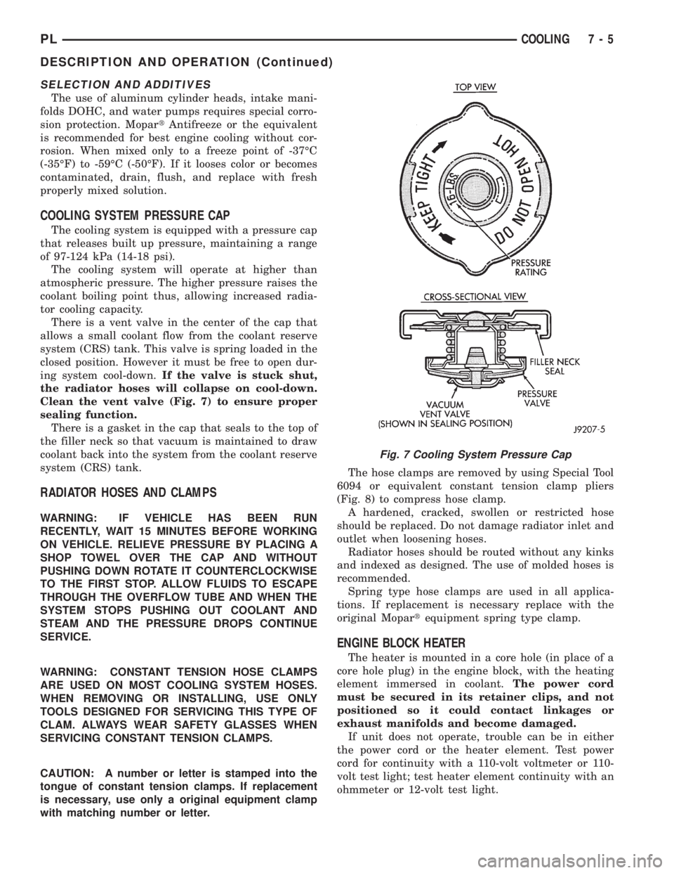
There is a vent valve in the center of the cap that
allows a small coolant flow from the coolant reserve
system (CRS) tank. This valve is spring loaded in the
closed position. However it must be free to open dur-
ing system cool-down.If the valve is stuck shut,
the radiator hoses will collapse on cool-down.
Clean the vent valve (Fig. 7) to ensure proper
sealing function.
There is a gasket in the cap that seals to the top of
the filler neck so that vacuum is maintained to draw
coolant back into the system from the coolant reserve
system (CRS) tank.
RADIATOR HOSES AND CLAMPS
WARNING: IF VEHICLE HAS BEEN RUN
RECENTLY, WAIT 15 MINUTES BEFORE WORKING
ON VEHICLE. RELIEVE PRESSURE BY PLACING A
SHOP TOWEL OVER THE CAP AND WITHOUT
PUSHING DOWN ROTATE IT COUNTERCLOCKWISE
TO THE FIRST STOP. ALLOW FLUIDS TO ESCAPE
THROUGH THE OVERFLOW TUBE AND WHEN THE
SYSTEM STOPS PUSHING OUT COOLANT AND
STEAM AND THE PRESSURE DROPS CONTINUE
SERVICE.
WARNING: CONSTANT TENSION HOSE CLAMPS
ARE USED ON MOST COOLING SYSTEM HOSES.
WHEN REMOVING OR INSTALLING, USE ONLY
TOOLS DESIGNED FOR SERVICING THIS TYPE OF
CLAM. ALWAYS WEAR SAFETY GLASSES WHEN
SERVICING CONSTANT TENSION CLAMPS.
CAUTION: A number or letter is stamped into the
tongue of constant tension clamps. If replacement
is necessary, use only a original equipment clamp
with matching number or letter.The hose clamps are removed by using Special Tool
6094 or equivalent constant tension clamp pliers
(Fig. 8) to compress hose clamp.
A hardened, cracked, swollen or restricted hose
should be replaced. Do not damage radiator inlet and
outlet when loosening hoses.
Radiator hoses should be routed without any kinks
and indexed as designed. The use of molded hoses is
recommended.
Spring type hose clamps are used in all applica-
tions. If replacement is necessary replace with the
original Mopartequipment spring type clamp.
ENGINE BLOCK HEATER
The heater is mounted in a core hole (in place of a
core hole plug) in the engine block, with the heating
element immersed in coolant.The power cord
must be secured in its retainer clips, and not
positioned so it could contact linkages or
exhaust manifolds and become damaged.
If unit does not operate, trouble can be in either
the power cord or the heater element. Test power
cord for continuity with a 110-volt voltmeter or 110-
volt test light; test heater element continuity with an
ohmmeter or 12-volt test light.
Fig. 7 Cooling System Pressure Cap
PLCOOLING 7 - 5
DESCRIPTION AND OPERATION (Continued)
Page 220 of 1200
NOTE: BLACK OR DARK=0to75%state-of-charge
The battery is INADEQUATELY charged and must
be charged until green dot is visible, (12.4 volts or
greater) before the battery is tested or returned to
use. Refer to Causes of Battery Discharging in this
Group for more information.
NOTE: CLEAR COLOR = Replace Battery
WARNING: DO NOT CHARGE, ASSIST BOOST,
LOAD TEST, OR ADD WATER TO THE BATTERY
WHEN CLEAR COLOR DOT IS VISIBLE. PERSONAL
INJURY MAY OCCUR.
A clear color dot shows electrolyte level in battery
is below the test indicator (Fig. 1). Water cannot be
added to a maintenance free battery. The battery
must be replaced. A low electrolyte level may be
caused by an over charging condition. Refer to Gen-
erator Test Procedures on Vehicle.
CAUSES OF BATTERY DISCHARGING
It is normal to have a small 5 to 25 milliamperes
continuous electrical draw from the battery. This
draw will take place with the ignition in the OFF
position, and the courtesy, dome, storage compart-
ments, and engine compartment lights OFF. The con-
tinuous draw is due to various electronic features or
accessories that require electrical current with the
ignition OFF to function properly. When a vehicle is
not used over an extended period of approximately 20
days the IOD fuse should be pulled. The fuse is
located in the power distribution center. removal of
this fuse will reduce the level of battery discharge.
Refer to the Battery Diagnosis and Testing Table for
proper diagnosis.
ABNORMAL BATTERY DISCHARGING
²Corroded battery posts, cables or terminals.
²Loose or worn generator drive belt.
²Electrical loads that exceed the output of the
charging system due to equipment or accessories
installed after delivery.
²Slow driving speeds in heavy traffic conditions
or prolonged idling with high-amperage electrical
systems in use.
²Defective electrical circuit or component causing
excess Ignition Off Draw (IOD). Refer to Battery
Ignition Off Draw (IOD).
²Defective charging system.
²Defective battery.
BATTERY IGNITION OFF DRAW (IOD)
High current draw on the battery with the ignition
OFF will discharge a battery. After a dead battery is
recharged, the vehicle ignition off draw (IOD) shouldbe checked. To determine if a high current draw con-
dition exists first check the vehicle with a test lamp.
(1) Verify that all electrical accessories are OFF.
²Remove key from ignition switch
²Turn off all lights
²Trunk lid is closed
²Engine compartment hood lamp is disconnected
or lamp removed
²Glove box door is closed
²Sun visor vanity lights are OFF
²All doors are closed
²Allow the ignition key lamp system to time out
in approximately 30 seconds, if equipped.
(2) Disconnect battery negative cable (Fig. 4).
(3) Connect a 12 Volt test lamp, with a cold resis-
tance of 5-7 ohms, between the battery negative cable
clamp and the negative post (Fig. 5). If test lamp
goes out system is OK. If test lamp lights and stays
ON, go to Test Lamp Stays ON procedure.
TEST LAMP STAYS ON
There is either a short circuit or a fault in an elec-
tronic module. Two fuses in the Power Distribution
Center (PDC) feed the modules with ignition off
draw.
²Interior lamps fuse (10 Amp) (IOD) PDC.
²Fuel pump fuse (20 Amp) in PDC
(1) Remove interior lamp and fuel pump fuses. By
removing these fuses all ignition off draw from the
vehicle electronics will be disconnected. The test
lamp should go out. If test lamp goes out go to Step
2. If test lamp does not go out there is a current
draw or short circuit. Refer to Group 8W, Wiring Dia-
grams.
(2) Install the fuel pump fuse. If test lamp lights,
there is a current draw or short circuit in the A14
wiring circuit feed.
(a) Disconnect Powertrain Control Module.
(b) If test lamp goes out, replace Powertrain
Control Module.
(c) If test lamp does not go out, there is a cur-
rent draw or short circuit in the A14 circuit feed.
Refer to Group 8W, Wiring Diagrams.
(3) Install the interior lamp fuse. If test lamp
lights, there is a current draw or short circuit in the
M01 circuit. Refer to Group 8W, Wiring Diagrams. If
test lamp stays out, go to Step 4
(4) Use a multi-meter that has at least a range of
200 milliamperes. Install meter between the battery
negative cable and battery negative post (Fig. 6).
Carefully remove the test lamp without disconnecting
the meter. After all modules time-out the total vehi-
cle IOD should be less than 10 milliamperes. If igni-
tion off draw is more than 10 milliamperes go to Step
5.
(5) Remove both fuses from the Power Distribution
Center:
PLBATTERY 8A - 3
DIAGNOSIS AND TESTING (Continued)
Page 270 of 1200
INSTRUMENT PANEL AND SYSTEMS
CONTENTS
page page
GENERAL INFORMATION
INTRODUCTION......................... 1
DESCRIPTION AND OPERATION
DOME LAMP............................ 1
ELECTRONIC DIGITAL CLOCK.............. 1
INSTRUMENT CLUSTER................... 2
WARNING AND INDICATOR LAMPS......... 2
DIAGNOSIS AND TESTING
AIRBAG WARNING SYSTEM............... 2
BRAKE SYSTEM WARNING LAMP TEST...... 2
FOG LAMP SWITCH TEST................. 2
FUEL TANK SENDING UNIT TEST........... 3
HEADLAMP SWITCH TEST................. 3
HEATER A/C BLOWER SWITCH TEST........ 3
HEATER BLOWER SWITCH TEST............ 3
INDIVIDUAL GAUGE INOPERATIVE.......... 4
INSTRUMENT PANEL AND COMPONENTS.... 4
LOW OIL PRESSURE WARNING LAMP TEST . . 4
MULTIPLE GAUGE INOPERATIVE TEST....... 4
SEAT BELT REMINDER SYSTEM TEST....... 6
SENDING UNIT......................... 6
SERVICE ENGINE SOON INDICATOR......... 6
VEHICLE SPEED SENSOR TEST............. 6
REMOVAL AND INSTALLATION
ASH RECEIVER RETAINER AND LAMP....... 6
CENTER BEZEL.......................... 6
CIGAR LIGHTER RECEPTACLE.............. 6
CLUSTER LAMP......................... 7
CLUSTER PRINTED CIRCUIT BOARD........ 7CLUSTER.............................. 7
DOME LENS/LAMP....................... 8
FLOOR CONSOLE........................ 8
GAUGE................................ 8
GLOVE BOX DOOR/BIN................... 8
GLOVE BOX SWITCH/LAMP................ 9
HEADLAMP SWITCH..................... 9
HEATER A/C CONTROL BLOWER SWITCH . . . 10
HEATER A/C CONTROL LAMP............ 10
HEATER A/C CONTROL................... 9
HEATER CONTROL BLOWER SWITCH....... 10
IGNITION KEY LAMP.................... 10
INSTRUMENT PANEL.................... 10
LEFT TRIM PANEL...................... 10
ODOMETER............................ 10
RADIO................................ 12
REAR WINDOW DEFOGGER AND/OR FOG
LAMP SWITCH....................... 12
RIGHT TRIM PANEL..................... 12
SHIFTER KNOB......................... 13
STEERING COLUMN COVER LINER......... 13
STEERING COLUMN COVER.............. 13
STEERING COLUMN SHROUDS............ 13
TOP COVER AND CLUSTER BEZEL
REMOVAL........................... 14
TRANSMISSION RANGE INDICATOR LAMP . . 14
TRUNK LAMP/LENS..................... 14
VEHICLE SPEED SENSOR................ 14
GENERAL INFORMATION
INTRODUCTION
The purpose of the dash gauges and indicator
lamps is to keep the driver informed about the oper-
ating condition of the vehicle. If an abnormal condi-
tion occurs, the driver is informed by indicator lamp.
The driver can seek service before damage occurs.
Indicator lamps use ON/OFF switch functions for
operation, while gauges use a sending unit or sensor.
DESCRIPTION AND OPERATION
DOME LAMP
The Dome Lamp operates when a door is open or
when the headlamp switch is placed in courtesy posi-
tion.
ELECTRONIC DIGITAL CLOCK
The electronic digital clock is in the radio. The
clock and radio each use the display panel built into
the radio. A digital readout indicates the time in
hours and minutes whenever the ignition switch is in
the ON or ACC position.
PLINSTRUMENT PANEL AND SYSTEMS 8E - 1
Page 271 of 1200
When the ignition switch is in the OFF position, or
when the radio frequency is being displayed, time
keeping is accurately maintained.
The procedure for setting the clock varies slightly
with each radio. The correct procedure is described in
the individual radio operating instructions. Refer to
the Owner's Manual supplied with the vehicle.
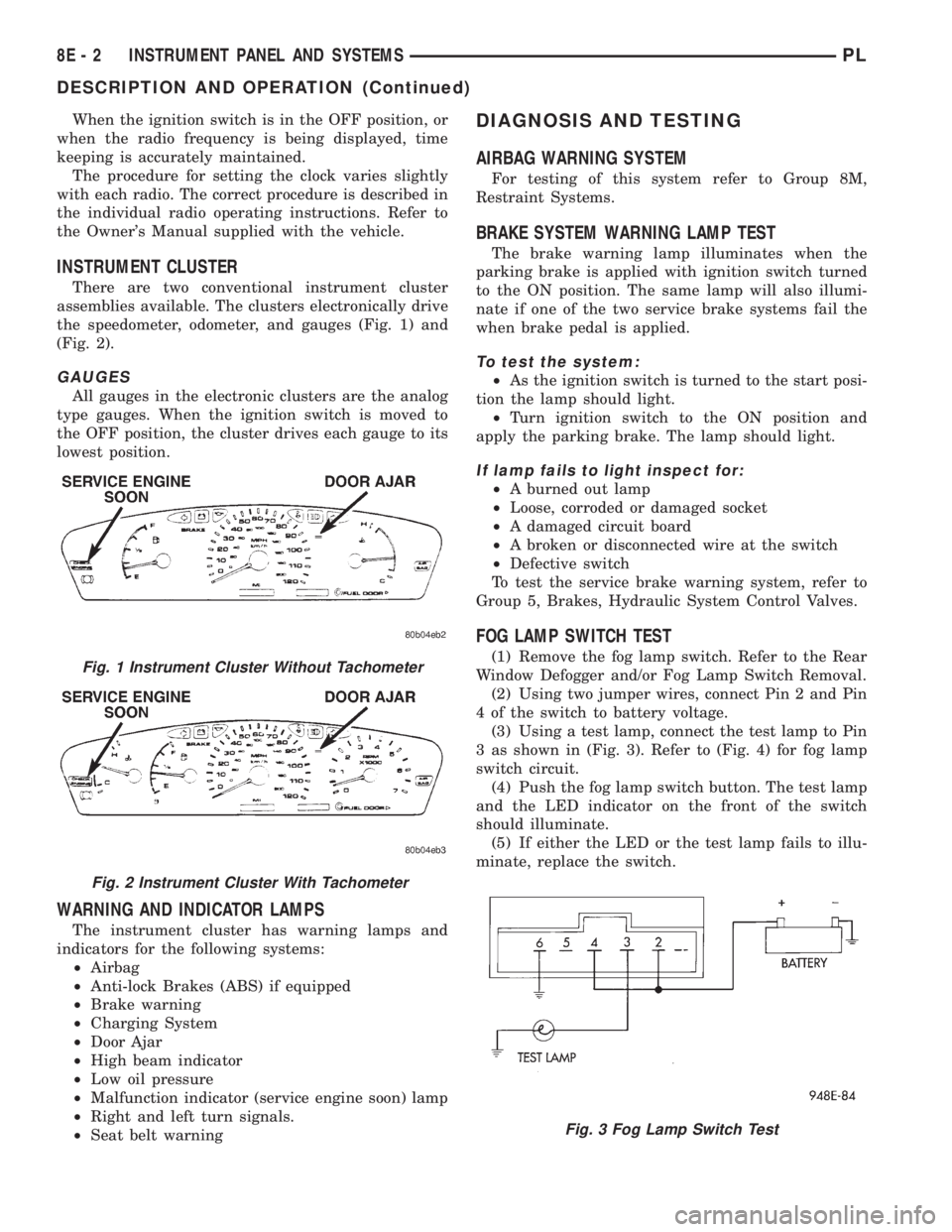
INSTRUMENT CLUSTER
There are two conventional instrument cluster
assemblies available. The clusters electronically drive
the speedometer, odometer, and gauges (Fig. 1) and
(Fig. 2).
GAUGES
All gauges in the electronic clusters are the analog
type gauges. When the ignition switch is moved to
the OFF position, the cluster drives each gauge to its
lowest position.
WARNING AND INDICATOR LAMPS
The instrument cluster has warning lamps and
indicators for the following systems:
²Airbag
²Anti-lock Brakes (ABS) if equipped
²Brake warning
²Charging System
²Door Ajar
²High beam indicator
²Low oil pressure
²Malfunction indicator (service engine soon) lamp
²Right and left turn signals.
²Seat belt warning
DIAGNOSIS AND TESTING
AIRBAG WARNING SYSTEM
For testing of this system refer to Group 8M,
Restraint Systems.
BRAKE SYSTEM WARNING LAMP TEST
The brake warning lamp illuminates when the
parking brake is applied with ignition switch turned
to the ON position. The same lamp will also illumi-
nate if one of the two service brake systems fail the
when brake pedal is applied.
To test the system:
²As the ignition switch is turned to the start posi-
tion the lamp should light.
²Turn ignition switch to the ON position and
apply the parking brake. The lamp should light.
If lamp fails to light inspect for:
²A burned out lamp
²Loose, corroded or damaged socket
²A damaged circuit board
²A broken or disconnected wire at the switch
²Defective switch
To test the service brake warning system, refer to
Group 5, Brakes, Hydraulic System Control Valves.
FOG LAMP SWITCH TEST
(1) Remove the fog lamp switch. Refer to the Rear
Window Defogger and/or Fog Lamp Switch Removal.
(2) Using two jumper wires, connect Pin 2 and Pin
4 of the switch to battery voltage.
(3) Using a test lamp, connect the test lamp to Pin
3 as shown in (Fig. 3). Refer to (Fig. 4) for fog lamp
switch circuit.
(4) Push the fog lamp switch button. The test lamp
and the LED indicator on the front of the switch
should illuminate.
(5) If either the LED or the test lamp fails to illu-
minate, replace the switch.Fig. 1 Instrument Cluster Without Tachometer
Fig. 2 Instrument Cluster With Tachometer
Fig. 3 Fog Lamp Switch Test
8E - 2 INSTRUMENT PANEL AND SYSTEMSPL
DESCRIPTION AND OPERATION (Continued)
Page 273 of 1200
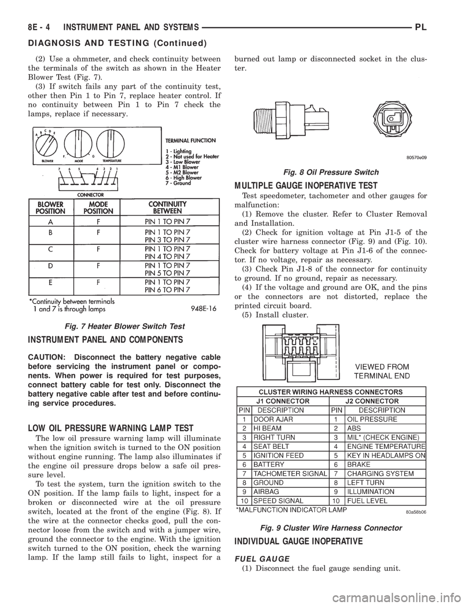
(2) Use a ohmmeter, and check continuity between
the terminals of the switch as shown in the Heater
Blower Test (Fig. 7).
(3) If switch fails any part of the continuity test,
other then Pin 1 to Pin 7, replace heater control. If
no continuity between Pin 1 to Pin 7 check the
lamps, replace if necessary.
INSTRUMENT PANEL AND COMPONENTS
CAUTION: Disconnect the battery negative cable
before servicing the instrument panel or compo-
nents. When power is required for test purposes,
connect battery cable for test only. Disconnect the
battery negative cable after test and before continu-
ing service procedures.
LOW OIL PRESSURE WARNING LAMP TEST
The low oil pressure warning lamp will illuminate
when the ignition switch is turned to the ON position
without engine running. The lamp also illuminates if
the engine oil pressure drops below a safe oil pres-
sure level.
To test the system, turn the ignition switch to the
ON position. If the lamp fails to light, inspect for a
broken or disconnected wire at the oil pressure
switch, located at the front of the engine (Fig. 8). If
the wire at the connector checks good, pull the con-
nector loose from the switch and with a jumper wire,
ground the connector to the engine. With the ignition
switch turned to the ON position, check the warning
lamp. If the lamp still fails to light, inspect for aburned out lamp or disconnected socket in the clus-
ter.
MULTIPLE GAUGE INOPERATIVE TEST
Test speedometer, tachometer and other gauges for
malfunction:
(1) Remove the cluster. Refer to Cluster Removal
and Installation.
(2) Check for ignition voltage at Pin J1-5 of the
cluster wire harness connector (Fig. 9) and (Fig. 10).
Check for battery voltage at Pin J1-6 of the connec-
tor. If no voltage, repair as necessary.
(3) Check Pin J1-8 of the connector for continuity
to ground. If no ground, repair as necessary.
(4) If the voltage and ground are OK, and the pins
or the connectors are not distorted, replace the
printed circuit board.
(5) Install cluster.
INDIVIDUAL GAUGE INOPERATIVE
FUEL GAUGE
(1) Disconnect the fuel gauge sending unit.
Fig. 7 Heater Blower Switch Test
Fig. 8 Oil Pressure Switch
Fig. 9 Cluster Wire Harness Connector
8E - 4 INSTRUMENT PANEL AND SYSTEMSPL
DIAGNOSIS AND TESTING (Continued)
Page 275 of 1200

(8) If all tests performed test good, replace the dial
and gauge assembly.
(9) If the tachometer continues to be inoperative,
replace the print circuit board.
TEMPERATURE GAUGE
(1) Disconnect the coolant temperature sensor
(Fig. 12).
(2) Turn ignition switch ON. The temperature
gauge should be at its lowest position. Turn ignition
switch OFF.
(3) Ground temperature gauge sending unit con-
nector Pin 3. Refer to Group 8W, wiring Diagrams.
Turn ignition switch ON. The temperature gauge
should be at its highest position. After the seat belt
lamp goes out, the cluster should chime for about
eight seconds.
(a) If OK, check temperature sending unit con-
nector for proper connection. If connections are OK,
replace the sending unit.
(b) If not OK, and the high temperature chime
sounds but the gauge shows cold, replace the gauge
assembly. If gauge is still not working, replace the
printed circuit board.
SPEEDOMETER SYSTEM
The vehicle is equipped with a electronically driven
speedometer and odometer assemblies. A signal is
sent from a transmission-mounted vehicle speed sen-
sor to the speedometer circuitry through the wiring
harness.
SEAT BELT REMINDER SYSTEM TEST
For testing of this system refer to Group 8U,
Chime Warning/Reminder Systems.
SENDING UNIT
When a problem occurs with a cluster gauge check
for a defective sending unit or wiring. Do this before
disassembling the cluster.(1) Sending units and wiring can be checked by
grounding the connector leads at the sending unit in
the vehicle.
(2) With the ignition in the ON position, a
grounded input will cause the fuel or temperature
gauge to read at or above maximum.
SERVICE ENGINE SOON INDICATOR
Refer to Group 25, Emission Control Systems for
procedures.
VEHICLE SPEED SENSOR TEST
To test the vehicle speed sensor and related compo-
nents use a scan tool (DRB), and refer to the appro-
priate Powertrain Diagnostics Test Procedure
Manual.
REMOVAL AND INSTALLATION
ASH RECEIVER RETAINER AND LAMP
REMOVAL
(1) Open up and remove the ash receiver recepta-
cle.
(2) Remove the center bezel.
(3) Remove the two ash receiver retainer attaching
screws from the upper-rearward face and remove
retainer.
(4) For lamp replacement, remove the clamp and
lamp hood from the top of the retainer. Remove the
wiring clip at the forward edge of the retainer and
remove the lamp socket from the hood and replace
lamp.
INSTALLATION
For installation reverse the above procedures.
When installing the retainer ensure that the forward
tabs are inserted properly into the slots in the instru-
ment panel.
CENTER BEZEL
REMOVAL
(1) Open the ash receiver receptacle.
(2) Grasp the bezel and pull rearward disengaging
the clips.
INSTALLATION
For installation, reverse the above procedures.
CIGAR LIGHTER RECEPTACLE
REMOVAL
(1) Remove the cigar lighter element.
(2) Reach underneath the instrument panel
through the bottom access hole and disconnect the
cigar lighter receptacle wiring connectors.
Fig. 12 Engine Coolant Temperature Sensor
8E - 6 INSTRUMENT PANEL AND SYSTEMSPL
DIAGNOSIS AND TESTING (Continued)
Page 311 of 1200
DIAGNOSIS AND TESTING
MULTI-FUNCTION SWITCH
The multi-function switch contains electrical cir-
cuitry for turn signal, hazard warning, headlamp
beam select, headlamp optical horn. This integratedswitch assembly is mounted to the left hand side of
the steering column. Should any function of the
switch fail, the entire switch assembly must be
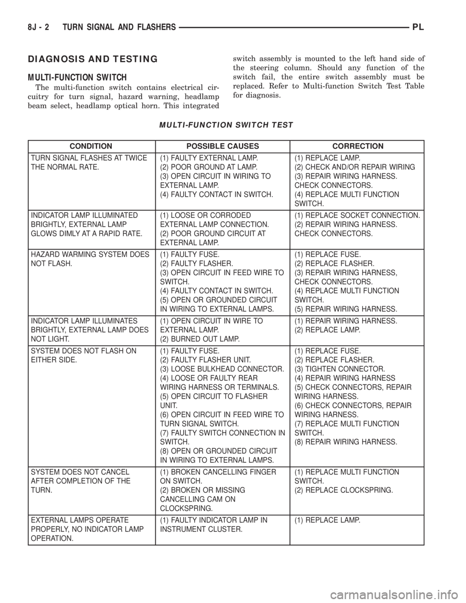
replaced. Refer to Multi-function Switch Test Table
for diagnosis.
MULTI-FUNCTION SWITCH TEST
CONDITION POSSIBLE CAUSES CORRECTION
TURN SIGNAL FLASHES AT TWICE
THE NORMAL RATE.(1) FAULTY EXTERNAL LAMP.
(2) POOR GROUND AT LAMP.
(3) OPEN CIRCUIT IN WIRING TO
EXTERNAL LAMP.
(4) FAULTY CONTACT IN SWITCH.(1) REPLACE LAMP.
(2) CHECK AND/OR REPAIR WIRING
(3) REPAIR WIRING HARNESS.
CHECK CONNECTORS.
(4) REPLACE MULTI FUNCTION
SWITCH.
INDICATOR LAMP ILLUMINATED
BRIGHTLY, EXTERNAL LAMP
GLOWS DIMLY AT A RAPID RATE.(1) LOOSE OR CORRODED
EXTERNAL LAMP CONNECTION.
(2) POOR GROUND CIRCUIT AT
EXTERNAL LAMP.(1) REPLACE SOCKET CONNECTION.
(2) REPAIR WIRING HARNESS.
CHECK CONNECTORS.
HAZARD WARMING SYSTEM DOES
NOT FLASH.(1) FAULTY FUSE.
(2) FAULTY FLASHER.
(3) OPEN CIRCUIT IN FEED WIRE TO
SWITCH.
(4) FAULTY CONTACT IN SWITCH.
(5) OPEN OR GROUNDED CIRCUIT
IN WIRING TO EXTERNAL LAMPS.(1) REPLACE FUSE.
(2) REPLACE FLASHER.
(3) REPAIR WIRING HARNESS,
CHECK CONNECTORS.
(4) REPLACE MULTI FUNCTION
SWITCH.
(5) REPAIR WIRING HARNESS.
INDICATOR LAMP ILLUMINATES
BRIGHTLY, EXTERNAL LAMP DOES
NOT LIGHT.(1) OPEN CIRCUIT IN WIRE TO
EXTERNAL LAMP.
(2) BURNED OUT LAMP.(1) REPAIR WIRING HARNESS.
(2) REPLACE LAMP.
SYSTEM DOES NOT FLASH ON
EITHER SIDE.(1) FAULTY FUSE.
(2) FAULTY FLASHER UNIT.
(3) LOOSE BULKHEAD CONNECTOR.
(4) LOOSE OR FAULTY REAR
WIRING HARNESS OR TERMINALS.
(5) OPEN CIRCUIT TO FLASHER
UNIT.
(6) OPEN CIRCUIT IN FEED WIRE TO
TURN SIGNAL SWITCH.
(7) FAULTY SWITCH CONNECTION IN
SWITCH.
(8) OPEN OR GROUNDED CIRCUIT
IN WIRING TO EXTERNAL LAMPS.(1) REPLACE FUSE.
(2) REPLACE FLASHER.
(3) TIGHTEN CONNECTOR.
(4) REPAIR WIRING HARNESS
(5) CHECK CONNECTORS, REPAIR
WIRING HARNESS.
(6) CHECK CONNECTORS, REPAIR
WIRING HARNESS.
(7) REPLACE MULTI FUNCTION
SWITCH.
(8) REPAIR WIRING HARNESS.
SYSTEM DOES NOT CANCEL
AFTER COMPLETION OF THE
TURN.(1) BROKEN CANCELLING FINGER
ON SWITCH.
(2) BROKEN OR MISSING
CANCELLING CAM ON
CLOCKSPRING.(1) REPLACE MULTI FUNCTION
SWITCH.
(2) REPLACE CLOCKSPRING.
EXTERNAL LAMPS OPERATE
PROPERLY, NO INDICATOR LAMP
OPERATION.(1) FAULTY INDICATOR LAMP IN
INSTRUMENT CLUSTER.(1) REPLACE LAMP.
8J - 2 TURN SIGNAL AND FLASHERSPL