Page 17 of 79
24-15
Fig. 5 Installation position, Throttle Position (TP) sensor -G79-
and sender 2 for accelerator pedal position -G185-
Fig. 6 Installation positions in E-box, plenum chamber
1 - Engine Control Module (ECM)
2 - Secondary Air Injection (AIR) pump relay -J299-
3 - Motronic Engine Control Module (ECM) voltage supply relay -J271-
4 - Installation location of fuse S130 for Secondary Air Injection (AIR)
pump
Pa
ge 17 of 79 Motronic in
jection s
ystem, servicin
g
11/22/2002 htt
p://127.0.0.1:8080/audi/servlet/Dis
play?action=Goto&t
yp
e=re
pair&id=AUDI.B5.FU07.24.1
Page 18 of 79
24-16
Charge air pressure sensor -G31- (arrow) bolted into charge air cooler at
top Fig. 7 Installation location, charge air pressure sensor -G31-
Pa
ge 18 of 79 Motronic in
jection s
ystem, servicin
g
11/22/2002 htt
p://127.0.0.1:8080/audi/servlet/Dis
play?action=Goto&t
yp
e=re
pair&id=AUDI.B5.FU07.24.1
Page 19 of 79
24-17
Air cleaner, disassembling and
assembling
1 -
Lower part of air cleaner housing
2 -
Sleeve
3 -
Rubber grommet
4 -
Air duct
to metering unit
5 -
Seal
6 -
Mass Air Flow (MAF) sensor -G70- Checking Page 24
-59
7 -
Air duct
8 -
6 Nm
9 -
Upper part of air cleaner housing
Pa
ge 19 of 79 Motronic in
jection s
ystem, servicin
g
11/22/2002 htt
p://127.0.0.1:8080/audi/servlet/Dis
play?action=Goto&t
yp
e=re
pair&id=AUDI.B5.FU07.24.1
Page 20 of 79
24-18
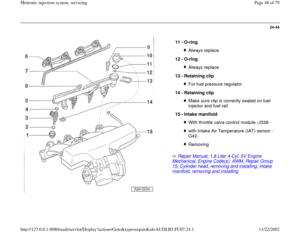
Repair Manual, Maintenance
10 -
Wire
For EVAP canister system
11 -
10 Nm
12 -
Heat shield
13 -
Filter element Follow filter change intervals
14 -
10 Nm
15 -
Rubber grommet
Pa
ge 20 of 79 Motronic in
jection s
ystem, servicin
g
11/22/2002 htt
p://127.0.0.1:8080/audi/servlet/Dis
play?action=Goto&t
yp
e=re
pair&id=AUDI.B5.FU07.24.1
Page 21 of 79
24-19
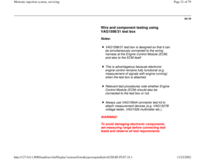
Wire and component testing using
VAG1598/31 test box
Notes:
VAG1598/31 test box is designed so that it can
be simultaneously connected to the wiring
harness at the Engine Control Module (ECM)
and also to the ECM itself.
This is advantageous because electronic
engine control remains fully functional (e.g.
measurement of signals with engine running)
when the test box is attached.
Relevant test procedures note whether Engine
Control Module (ECM) should also be
connected to the test box or not.
Always use VAG1594A connector test kit to
attach measurement devices (e.g. VAG1527B
voltage tester, VAG1526 multimeter etc.).
WARNING!
To avoid damaging electronic components,
set measuring range before connecting test
leads and observe all test requirements.
Pa
ge 21 of 79 Motronic in
jection s
ystem, servicin
g
11/22/2002 htt
p://127.0.0.1:8080/audi/servlet/Dis
play?action=Goto&t
yp
e=re
pair&id=AUDI.B5.FU07.24.1
Page 22 of 79
24-20
Special Tools and Equipment
Procedure
VAG1598/31
- Switch ignition off.
- Remove Engine Control Module (ECM) Page 24
-22
.
After re-connecting the Engine Control Module (ECM), the following
work steps must be performed: - Connect VAG1598/31 test box to connector of wiring harness. Connect
Ground (GND) clip at test box (not visible in illustration) to Ground
(GND). Relevant test procedures note whether Engine Control Module
(ECM) should also be connected to the test box.
- Perform test as described in relevant repair sequence.
- Activate Engine Control Module (ECM) in "Guided Troubleshooting"
below diagnostic object "Engine Control Module (ECM), replacing".
Pa
ge 22 of 79 Motronic in
jection s
ystem, servicin
g
11/22/2002 htt
p://127.0.0.1:8080/audi/servlet/Dis
play?action=Goto&t
yp
e=re
pair&id=AUDI.B5.FU07.24.1
Page 23 of 79
24-21
Procedure following interruption of
voltage supply
After re-connecting voltage supply, the
following work steps must be performed:
- Activate Engine Control Module (ECM) in
"Guided Troubleshooting" below diagnostic
object "Engine Control Module (ECM),
replacing".
Pa
ge 23 of 79 Motronic in
jection s
ystem, servicin
g
11/22/2002 htt
p://127.0.0.1:8080/audi/servlet/Dis
play?action=Goto&t
yp
e=re
pair&id=AUDI.B5.FU07.24.1
Page 24 of 79
24-22
Engine Control Module (ECM), replacing
Special Tools and Equipment
Removing
VAS5051 with VAG5051/1
- Connect VAS5051 tester Page 01
-7 and select vehicle system "01 -
Engine electronics". Ignition must remain switched on for this.
VAS5051 tester display will indicate the control module identification and
coding -2-.
- Always allow display of control module identification first and print it
out.
- Compare coding with coding versions Page 01
-73
.
Pa
ge 24 of 79 Motronic in
jection s
ystem, servicin
g
11/22/2002 htt
p://127.0.0.1:8080/audi/servlet/Dis
play?action=Goto&t
yp
e=re
pair&id=AUDI.B5.FU07.24.1


 sensor -G79-
and sender 2 for accelerator pedal position -G185-
Fig. 6 Installation positions in E-box, plenum chamber
1 - En")
 bolted into charge air cooler at
top Fig. 7 Installation location, charge air pressure sensor -G31-
Pa
ge 18 of 79 Motronic in
jection s
ystem,")
 se")


 Page 24
-22
.
After re-connecting the Engine Control Module")
")
, replacing
Special Tools and Equipment
Removing
VAS5051 with VAG5051/1
- Connect VAS5051 tester Page 01
-7 and select vehicle system \"01 -")