Page 9 of 79
24-8
10 -
Instrument cluster
with exhaust Malfunction Indicator Lamp
(MIL). Notes for Malfunction Indicator Lamp
(MIL) Page 01
-3
with Electronic Power Control (EPC)
warning lamp -K132- (EPC warning lamp).
Significance of EPC warning lamp Page 24
-122
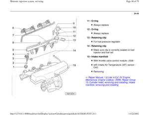
11 -
Throttle Position (TP) sensor -G79- and
sender 2 for accelerator pedal position -
G185-
Component location Fig. 5
, Page
24
-15
Checking Page 24
-138
Adapt kick down function Page 24
-145
12 -
Brake light switch -F- and brake pedal
switch -F47-
Component location Fig. 3
, Page
24
-14
Pa
ge 9 of 79 Motronic in
jection s
ystem, servicin
g
11/22/2002 htt
p://127.0.0.1:8080/audi/servlet/Dis
play?action=Goto&t
yp
e=re
pair&id=AUDI.B5.FU07.24.1
Page 10 of 79
24-9
Repair Manual, 1.8 Liter 4
-Cyl. 5V Turbo Engine
Mechanical, Engine Code(s): AWM, Repair Group 26; Secondary Air Injection (AIR) system, checking
13 -
E-box, plenum chamber
Installation locations Fig. 6
, Page
24
-15
Installation location for motronic Engine
Control Module (ECM) -J220- with
integrated Barometric pressure (BARO)
sensor -F96- Check voltage supply of Engine Control
Module (ECM) Page 28
-37
Procedure to follow after open circuit in
voltage supply Page 24
-21
Replacing Engine Control Module (ECM)
Page 24
-22
Installation location of Secondary Air
Injection (AIR) pump relay -J299- Check Secondary Air Injection (AIR) pump
relay -J299-: Installation location of motronic Engine
Control Module (ECM) voltage supply relay
-J271- Check motronic Engine Control Module
Pa
ge 10 of 79 Motronic in
jection s
ystem, servicin
g
11/22/2002 htt
p://127.0.0.1:8080/audi/servlet/Dis
play?action=Goto&t
yp
e=re
pair&id=AUDI.B5.FU07.24.1
Page 11 of 79
(ECM) voltage supply relay -J271- Page 28
-13
Installation location of fuse S130 for
Secondary Air Injection (AIR) pump
Pa
ge 11 of 79 Motronic in
jection s
ystem, servicin
g
11/22/2002 htt
p://127.0.0.1:8080/audi/servlet/Dis
play?action=Goto&t
yp
e=re
pair&id=AUDI.B5.FU07.24.1
Page 12 of 79
24-10
Repair Manual, 1.8 Liter 4
-Cyl. 5V Turbo Engine
Mechanical, Engine Code(s): AWM, Repair Group 21, Charge air system with turbocharger, checking
14 -
Clutch vacuum vent valve switch -F36-
Component location Fig. 3
, Page
24
-14
15 -
Charge air pressure sensor -G31-
Installation location Fig. 7
, Page
24
-16
Checking:
16 -
Throttle valve control module -J338-
With throttle drive (power accelerator
actuation) -G186-, angle sensor -1- for
throttle drive (power accelerator actuation)
-G187-, and angle sensor -2- for throttle
drive (power accelerator actuation) -G188- Checking Page 24
-124
Pa
ge 12 of 79 Motronic in
jection s
ystem, servicin
g
11/22/2002 htt
p://127.0.0.1:8080/audi/servlet/Dis
play?action=Goto&t
yp
e=re
pair&id=AUDI.B5.FU07.24.1
Page 13 of 79
24-11
17 -
Intake Air Temperature (IAT) sensor -G42-
Checking Page 28
-21
18 -
Recirculating valve for turbocharger-
N249-
Installation location Fig. 4
, Page
24
-14
Blue harness connector
19 -
Knock Sensor (KS) 1 -G61-
20 -
Knock Sensor (KS) 2 -G66-
21 -
Camshaft Position (CMP) sensor 2 -G40- Checking Page 28
-49
22 -
Fuel injector
Cylinder 1 Fuel Injector -N30-Cylinder 2 fuel injector -N31-Cylinder 3 fuel injector -N32-Cylinder 4 fuel injector -N33-Checking Page 24
-37
Removing and installing Page 24
-45
Pa
ge 13 of 79 Motronic in
jection s
ystem, servicin
g
11/22/2002 htt
p://127.0.0.1:8080/audi/servlet/Dis
play?action=Goto&t
yp
e=re
pair&id=AUDI.B5.FU07.24.1
Page 14 of 79
24-12
Repair Manual, 1.8 Liter 4
-Cyl. 5V Turbo Engine
Mechanical, Engine Code(s): AWM, Repair Group 21, Charge air system with turbocharger, checking
Repair Manual, 1.8 Liter 4
-Cyl. 5V Turbo Engine
Mechanical, Engine Code(s): AWM, Repair Group 26; Secondary Air Injection (AIR) system, checking
23 -
Ignition coil
Ignition coil -N-Ignition coil 2 -N128-Ignition coil 3 -N158-Ignition coil 4 -N163-Checking Page 28
-4
24 -
Wastegate bypass regulator valve -N75-
Checking:
25 -
Mass Air Flow (MAF) sensor -G70-
Checking Page 24
-59
26 -
Secondary Air Injection (AIR) pump
motor-V101-
Checking:
Pa
ge 14 of 79 Motronic in
jection s
ystem, servicin
g
11/22/2002 htt
p://127.0.0.1:8080/audi/servlet/Dis
play?action=Goto&t
yp
e=re
pair&id=AUDI.B5.FU07.24.1
Page 15 of 79
24-13
The following harness connectors are located below the coolant
expansion tank: Fig. 1 Installation location, harness connectors
1 - 4-pin harness connector, brown
for Oxygen Sensor (O2S) behind Three Way Catalytic Converter
(TWC) -G130- and Oxygen Sensor (O2S) Heater 1 -Z29- (bank 1
sensor 2)
2 - 6-pin harness connector, black
for Heated Oxygen Sensor (HO2S) -G39- beforecatalytic converter
and Oxygen Sensor (O2S) Heater -Z19- (bank 1 sensor 1)
3 - 3-pin harness connector, gray
for Engine Speed (RPM) sensor -G28-
4 - 3-pin harness connector, blue
for Knock Sensor (KS) 2 -G66-
5 - 3-pin harness connector, green
for Knock Sensor (KS) 1 -G61-
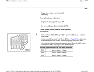
Fuel Pump (FP) Relay -J17- is located at position 4 of central electronics
in driver's footwell, left. Fig. 2 Component locations Fuel Pump (FP) Relay -J17-
Pa
ge 15 of 79 Motronic in
jection s
ystem, servicin
g
11/22/2002 htt
p://127.0.0.1:8080/audi/servlet/Dis
play?action=Goto&t
yp
e=re
pair&id=AUDI.B5.FU07.24.1
Page 16 of 79
24-14
Note:
In order to assure sufficiently secure fitting, switches must not be installed
more than once.
Adjusting switch:
Repair Manual, Brake System, Repair Group 46; Brake booster, removing and installing
Fig. 3 Installation location of brake light switch -F- and brake
pedal switch -F47-, clutch vacuum vent valve switch -F36-
1 - Clip
2 - Clutch vacuum vent valve switch -F36-
3 - Brake light switch -F-, brake pedal switch -F47-
Note:
Illustration depicts intake manifold removed, from below. Fig. 4 Installation location of Secondary Air Injection (AIR)
solenoid valve-N112- and recirculating valve for
turbocharger-N249-
Installation location: Below intake manifold
1 - Recirculating valve for turbocharger -N249-
2 - Secondary Air Injection (AIR) solenoid valve -N112-
Pa
ge 16 of 79 Motronic in
jection s
ystem, servicin
g
11/22/2002 htt
p://127.0.0.1:8080/audi/servlet/Dis
play?action=Goto&t
yp
e=re
pair&id=AUDI.B5.FU07.24.1


. Notes for Malfunction Indicator Lamp
(MIL) Page 01
-3
with Electronic Power Control (EPC)
warning lamp -K132- (E")
: AWM, Repair Group 26; Secondary Air Injection (AIR) system, checking
13 -
E-box, plenum chamber
Installat")
 voltage supply relay -J271- Page 28
-13
Installation location of fuse S130 for
Secondary Air Injection (AIR) pump
Pa
ge 11 of 79 Motronic in
jection s
ystem, servicin
g
11/22/2002 htt
p://")
: AWM, Repair Group 21, Charge air system with turbocharger, checking
14 -
Clutch vacuum vent valve switch")
 sensor -G42-
Checking Page 28
-21
18 -
Recirculating valve for turbocharger-
N249-
Installation location Fig. 4
, Page
24
-14
Blue harness con")
: AWM, Repair Group 21, Charge air system with turbocharger, checking
Repair Manual, 1.8 Liter 4
-Cyl. 5V T")

