Page 2440 of 3115
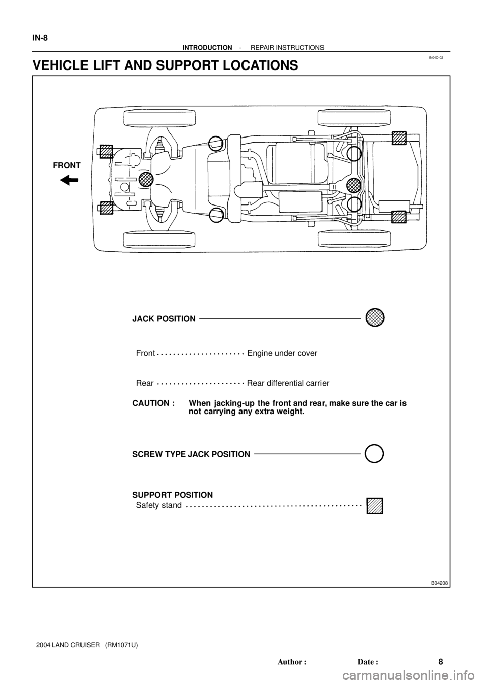
IN04O-02
B04208
SUPPORT POSITIONFront
RearEngine under cover
Rear differential carrier
CAUTION : When jacking-up the front and rear, make sure the car is
not carrying any extra weight.
Safety stand FRONT
JACK POSITION
SCREW TYPE JACK POSITION IN-8
- INTRODUCTIONREPAIR INSTRUCTIONS
8 Author�: Date�:
2004 LAND CRUISER (RM1071U)
VEHICLE LIFT AND SUPPORT LOCATIONS
Page 2446 of 3115
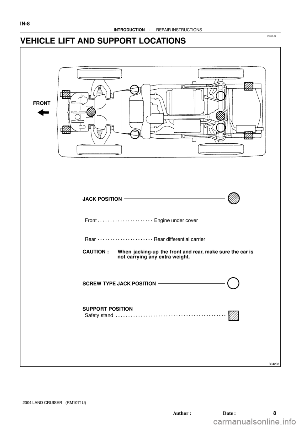
IN04O-02
B04208
SUPPORT POSITIONFront
RearEngine under cover
Rear differential carrier
CAUTION : When jacking-up the front and rear, make sure the car is
not carrying any extra weight.
Safety stand FRONT
JACK POSITION
SCREW TYPE JACK POSITION IN-8
- INTRODUCTIONREPAIR INSTRUCTIONS
8 Author�: Date�:
2004 LAND CRUISER (RM1071U)
VEHICLE LIFT AND SUPPORT LOCATIONS
Page 2472 of 3115
MA02U-07
B04566
Dust Cover
B04567
B06414
MA-8
- MAINTENANCECHASSIS
56 Author�: Date�:
CHASSIS
INSPECTION
1. INSPECT STEERING LINKAGE
(a) Check the steering linkage for looseness or damage.
(b) Check the tie rod ends do not have excessive play.
(c) Check the dust seals and boots are not damaged.
(d) Check the boot clamps are not loose.
(e) Check the inspect the dust cover for damage.
2. INSPECT SRS AIRBAG (See pages RS-18, RS-32)
3. INSPECT STEERING GEAR HOUSING OIL
Check the steering gear housing for oil leakage.
If leakage is found, check for cause and repair.
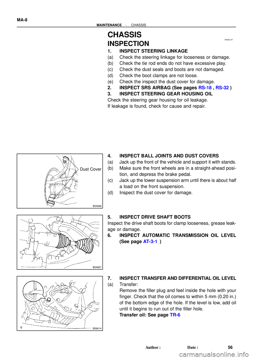
4. INSPECT BALL JOINTS AND DUST COVERS
(a) Jack up the front of the vehicle and support it with stands.
(b) Make sure the front wheels are in a straight-ahead posi-
tion, and depress the brake pedal.
(c) Jack up the lower suspension arm until there is about half
a load on the front suspension.
(d) Inspect the dust cover for damage.
5. INSPECT DRIVE SHAFT BOOTS
Inspect the drive shaft boots for clamp looseness, grease leak-
age or damage.
6. INSPECT AUTOMATIC TRANSMISSION OIL LEVEL
(See page AT-3-1)
7. INSPECT TRANSFER AND DIFFERENTIAL OIL LEVEL
(a) Transfer:
Remove the filler plug and feel inside the hole with your
finger. Check that the oil comes to within 5 mm (0.20 in.)
of the bottom edge of the hole. If the level is low, add oil
until it begins to run out of the filler hole.
Transfer oil: See page TR-6
Page 2611 of 3115

SS0OK-05
SS-38
- SERVICE SPECIFICATIONSSUSPENSION AND AXLE
178 Author�: Date�:
2004 LAND CRUISER (RM1071U)
TORQUE SPECIFICATION
FRONT
Part tightenedN´mkgf´cmft´lbf
Hub bolt1311,34097
Knuckle stopper bolt lock nut4445032
Steering knuckle x Brake caliper1231,25091
Disc x Axle hub7475055
Flange x Axle hub3333524
Axle hub bearing lock nut6465047
Flexible hose x Bracket2829021
ABS speed sensor installation bolt8.08271 in.´lbf
ABS speed sensor wire harness x Steering knuckle arm1313010
ABS speed sensor wire harness bracket x Steering knuckle2829021
Steering knuckle arm x Steering knuckle1471,500108
Tie rod end x Steering knuckle arm1221,25090
Upper suspension arm x Steering knuckle11 01,12581
Lower suspension arm x Steering knuckle1591,62511 7
Oil seal x Steering knuckle1818513
Propeller shaft x Companion flange8082059
Body x No. 3 frame crossmember6869550
No. 3 frame crossmember x Differential support1861,900137
Differential support x Differential tube1861,900137
Differential support x Differential carrier7880058
Differential support x Body1861,900137
Differential carrier cover x Body1861,900137
Breather hose bracket x Carrier cover1717313
Filler plug4950036
Drain plug4950036
Differential tube x Differential carrier1051,07077
Bearing cap x Differential carrier8587063
Oil deflector x Carrier cover7.37465 in.´lbf
Carrier cover x Differential carrier4747535
Differential case x Ring gear9798572
Companion flange x Drive pinionSee page SA-47
Lower suspension arm x Shock absorber1351,400100
Piston rod x Body6870050
Torque arm x Lower suspension arm2252,300166
ABS speed sensor wire harness x Upper suspension arm1313010
Upper suspension arm x Body981,00072
Stabilizer bar link x Lower suspension arm5253038
Lower suspension arm x Body2302,350170
Stabilizer bar x Stabilizer bar link2525018
Stabilizer bar bracket x Body1818513
Page 2903 of 3115
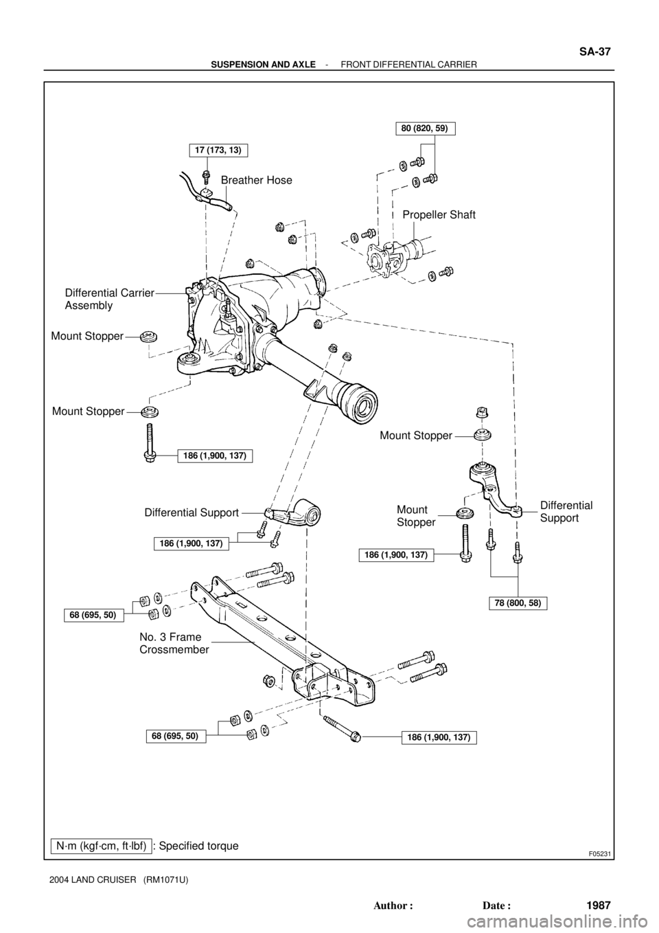
F05231N´m (kgf´cm, ft´lbf) : Specified torquePropeller Shaft
Differential
Support Mount StopperDifferential Carrier
AssemblyBreather Hose
No. 3 Frame
Crossmember
Mount Stopper
Mount Stopper
Mount
StopperDifferential Support
186 (1,900, 137)
17 (173, 13)
78 (800, 58)
68 (695, 50)
68 (695, 50)186 (1,900, 137)
186 (1,900, 137)
186 (1,900, 137)
80 (820, 59)
- SUSPENSION AND AXLEFRONT DIFFERENTIAL CARRIER
SA-37
1987 Author�: Date�:
2004 LAND CRUISER (RM1071U)
Page 2924 of 3115
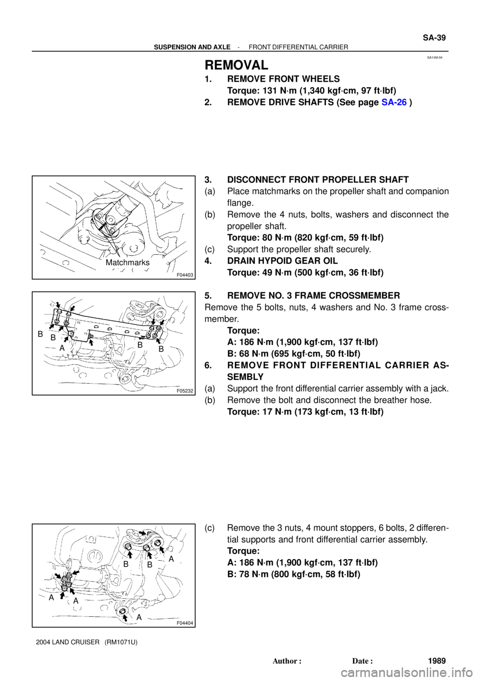
SA14M-04
F04403
Matchmarks
F05232
ABB
BB
F04404
A
A
BB
AA
- SUSPENSION AND AXLEFRONT DIFFERENTIAL CARRIER
SA-39
1989 Author�: Date�:
2004 LAND CRUISER (RM1071U)
REMOVAL
1. REMOVE FRONT WHEELS
Torque: 131 N´m (1,340 kgf´cm, 97 ft´lbf)
2. REMOVE DRIVE SHAFTS (See page SA-26)
3. DISCONNECT FRONT PROPELLER SHAFT
(a) Place matchmarks on the propeller shaft and companion
flange.
(b) Remove the 4 nuts, bolts, washers and disconnect the
propeller shaft.
Torque: 80 N´m (820 kgf´cm, 59 ft´lbf)
(c) Support the propeller shaft securely.
4. DRAIN HYPOID GEAR OIL
Torque: 49 N´m (500 kgf´cm, 36 ft´lbf)
5. REMOVE NO. 3 FRAME CROSSMEMBER
Remove the 5 bolts, nuts, 4 washers and No. 3 frame cross-
member.
Torque:
A: 186 N´m (1,900 kgf´cm, 137 ft´lbf)
B: 68 N´m (695 kgf´cm, 50 ft´lbf)
6. REMOVE FRONT DIFFERENTIAL CARRIER AS-
SEMBLY
(a) Support the front differential carrier assembly with a jack.
(b) Remove the bolt and disconnect the breather hose.
Torque: 17 N´m (173 kgf´cm, 13 ft´lbf)
(c) Remove the 3 nuts, 4 mount stoppers, 6 bolts, 2 differen-
tial supports and front differential carrier assembly.
Torque:
A: 186 N´m (1,900 kgf´cm, 137 ft´lbf)
B: 78 N´m (800 kgf´cm, 58 ft´lbf)
Page 2992 of 3115

SA15N-04
F04386
SST
F05217
F05080
Matchmarks
SA-100
- SUSPENSION AND AXLEREAR DIFFERENTIAL CARRIER
2050 Author�: Date�:
2004 LAND CRUISER (RM1071U)
REMOVAL
1. REMOVE 2 REAR WHEELS
Torque: 131 N´m (1,340 kgf´cm, 97 ft´lbf)
2. DRAIN HYPOID GEAR OIL
Torque: 49 N´m (500 kgf´cm, 36 ft´lbf)
3. DISCONNECT BRAKE LINES
(a) Using SST, disconnect the brake line and remove the clip.
SST 09023-00100
Torque: 15 N´m (150 kgf´cm, 11 ft´lbf)
(b) Employ the same manner described above to the other
side.
4. DISCONNECT PARKING BRAKE CABLES
(a) Remove the 2 clips, pin and disconnect the parking brake
cable from the bellcrank.
(b) Employ the same manner described above to the other
side.
5. REMOVE AXLE SHAFTS
(a) Remove the 4 nuts.
Torque: 123 N´m (1,250 kgf´cm, 90 ft´lbf)
(b) Pull out the axle shaft and remove the O-ring.
NOTICE:
Be careful not to damage the oil seal.
(c) Employ the same manner described above to the other
side.
6. DISCONNECT REAR PROPELLER SHAFT
(a) Place matchmarks on the propeller shaft and differential
flange.
(b) Remove the 4 nuts, bolts, washers and disconnect the
propeller shaft.
Torque: 106 N´m (1,080 kgf´cm, 78 ft´lbf)
(c) Support the propeller shaft securely.
Page 3015 of 3115

F05217
F05080
Matchmarks
F05932
SA-120
- SUSPENSION AND AXLEREAR DIFFERENTIAL CARRIER (w/ Diff. Lock)
2070 Author�: Date�:
2004 LAND CRUISER (RM1071U)
6. REMOVE AXLE SHAFTS
(a) Remove the 4 nuts.
Torque: 123 N´m (1,250 kgf´cm, 90 ft´lbf)
(b) Pull out the axle shaft assembly and remove the nut.
NOTICE:
Be careful not to damage the oil seal.
(c) Employ the same manner described above to the other
side.
7. DISCONNECT REAR PROPELLER SHAFT
(a) Place matchmarks on the propeller shaft and differential
flange.
(b) Remove the 4 nuts, bolts, washers and disconnect the
propeller shaft.
Torque: 106 N´m (1,080 kgf´cm, 78 ft´lbf)
(c) Support the propeller shaft securely.
8. REMOVE NO. 1 AND NO. 2 ACTUATOR PROTECTORS
(a) Remove the nut, bolt and No. 1 actuator protector.
Torque: 15 N´m (150 kgf´cm, 11 ft´lbf)
(b) Remove the 2 nuts and No. 2 actuator protector.
Torque: 36 N´m (367 kgf´cm, 27 ft´lbf)
9. DISCONNECT CONNECTORS AND HOSE
10. REMOVE DIFFERENTIAL CARRIER ASSEMBLY
(a) Remove the 10 nuts, washers and differential carrier as-
sembly.
NOTICE:
Be careful not to damage the installation surface.
Torque: 72 N´m (740 kgf´cm, 53 ft´lbf)
(b) Remove the gasket.
HINT:
At the time of installation, please refer to the following items.
�Before installation, connect the connectors of the actua-
tor to the connector on the vehicle side, check the differ-
ential lock is in operation.
�Before installation, check that the sleeves are in opera-
tion while switching over the differential lock control
switch.
�After installation, check that the rear differential lock is in
operation.