Page 2648 of 3115

Fuel pressure:
265 - 304 kPa (2.7 - 3.1 kgf/cm
2, 38 - 44 psi)
If pressure is higher than the specification,")
B16435
Ohmmeter
5
4
SF-8
- SFIFUEL PUMP
1707 Author�: Date�:
2004 LAND CRUISER (RM1071U)
Fuel pressure:
265 - 304 kPa (2.7 - 3.1 kgf/cm
2, 38 - 44 psi)
If pressure is higher than the specification, replace the fuel
pressure regulator.
If pressure is lower than the specification, check these parts:
�Fuel hoses and connections
�Fuel pump
�Fuel filter
�Fuel pressure regulator
(i) Disconnect the TOYOTA hand- held tester from the
DLC3.
(j) Start the engine.
(k) Measure the fuel pressure at idle.
Fuel pressure:
265 - 304 kPa (2.7 - 3.1 kgf/cm
2, 38 - 44 psi)
(l) Stop the engine.
(m) Check that the fuel pressure remains in the specification
below for 5 minutes after the engine stop.
Fuel pressure:
147 kPa (1.5 kgf/cm
2, 21 psi) or more
If the pressure is not as specified, check the fuel pump, pres-
sure regulator and/or the injectors.
(n) After checking the fuel pressure, disconnect the negative
(-) terminal cable from the battery and carefully remove
the SST to prevent gasoline from splashing.
SST 09268-45014
(o) Reinstall the front fuel pipe to the LH delivery pipe (See
page SF-27).
(p) Reconnect the negative (-) terminal cable to the battery.
(q) Check for fuel leaks (See page SF-1).
(r) Reinstall the V-bank cover with the 2 bolts and nuts.
(s) Reconnect the fuel return hose to the clamp on the V-
bank cover.
3. INSPECT FUEL PUMP
(a) Remove the No.1 rear seats.
(b) Remove the 2 rear door scuff plates, the step plates and
the rear seat lock covers.
(c) Pull off the front and rear floor carpets.
(d) Remove the 2 screws and the rear floor service hole cov-
er.
(e) Disconnect the fuel pump & sender gauge connector.
(f) Using an ohmmeter, measure the resistance between ter-
minal 4 and 5.
Page 2670 of 3115

(c) Do not a severe impact during removal or installation.
Handle all SFI parts")
FI2553
SST
B04902Fuel Pump Connector
Disconnect SF-2
- SFISFI SYSTEM
1701 Author�: Date�:
2004 LAND CRUISER (RM1071U)
(c) Do not a severe impact during removal or installation.
Handle all SFI parts carefully, especially the ECM.
(d) Be careful during the troubleshooting as there are numer-
ous transistor circuit, and even slight terminal contact can
cause further troubles.
(e) Do not open the ECM cover.
(f) When inspecting in rainy weather, take care to prevent
entry of water. Also, when washing the engine compart-
ment, prevent water from getting on the SFI parts and the
wiring connectors.
(g) Parts should be replaced as the original assembly.
(h) Care should be taken when pulling out and inserting the
wiring connectors.
(1) Release the lock and pull out the connector.
(2) Fully insert the connector and check that it is locked.
(i) Use SST for the inspection, the injector and the wiring
connector test.
SST 09842-30070
8. FUEL SYSTEM
(a) When disconnecting the high fuel pressure line, a large
amount of gasoline may be spilled:
(1) Disconnect the fuel pump connector.
(2) Start the engine. After the engine has stopped on
its own, turn the ignition switch OFF.
(3) Put a container under the connection.
(4) Slowly loosen the connection.
(5) Disconnect the connection.
(6) Plug the connection with a rubber plug.
(7) Reconnect the fuel pump connector.
Page 2816 of 3115
SR0LX-04
R11229
Normal Abnormal SR-4
- STEERINGPOWER STEERING FLUID
2213 Author�: Date�:
2004 LAND CRUISER (RM1071U)
POWER STEERING FLUID
BLEEDING
1. CHECK FLUID LEVEL (See page SR-5)
2. JACK UP FRONT OF VEHICLE AND SUPPORT IT
WITH STANDS
3. TURN STEERING WHEEL
With the engine stopped, turn the wheel slowly from lock to lock
several times.
4. LOWER VEHICLE
5. START ENGINE
Run the engine at idle for a few minutes.
6. TURN STEERING WHEEL
(a) With the engine idling, turn the wheel to left or right full
lock position and keep it there for 2-3 seconds, then turn
the wheel to the opposite full lock position and keep it
there for 2-3 seconds.
(b) Repeat (a) several times.
7. STOP ENGINE
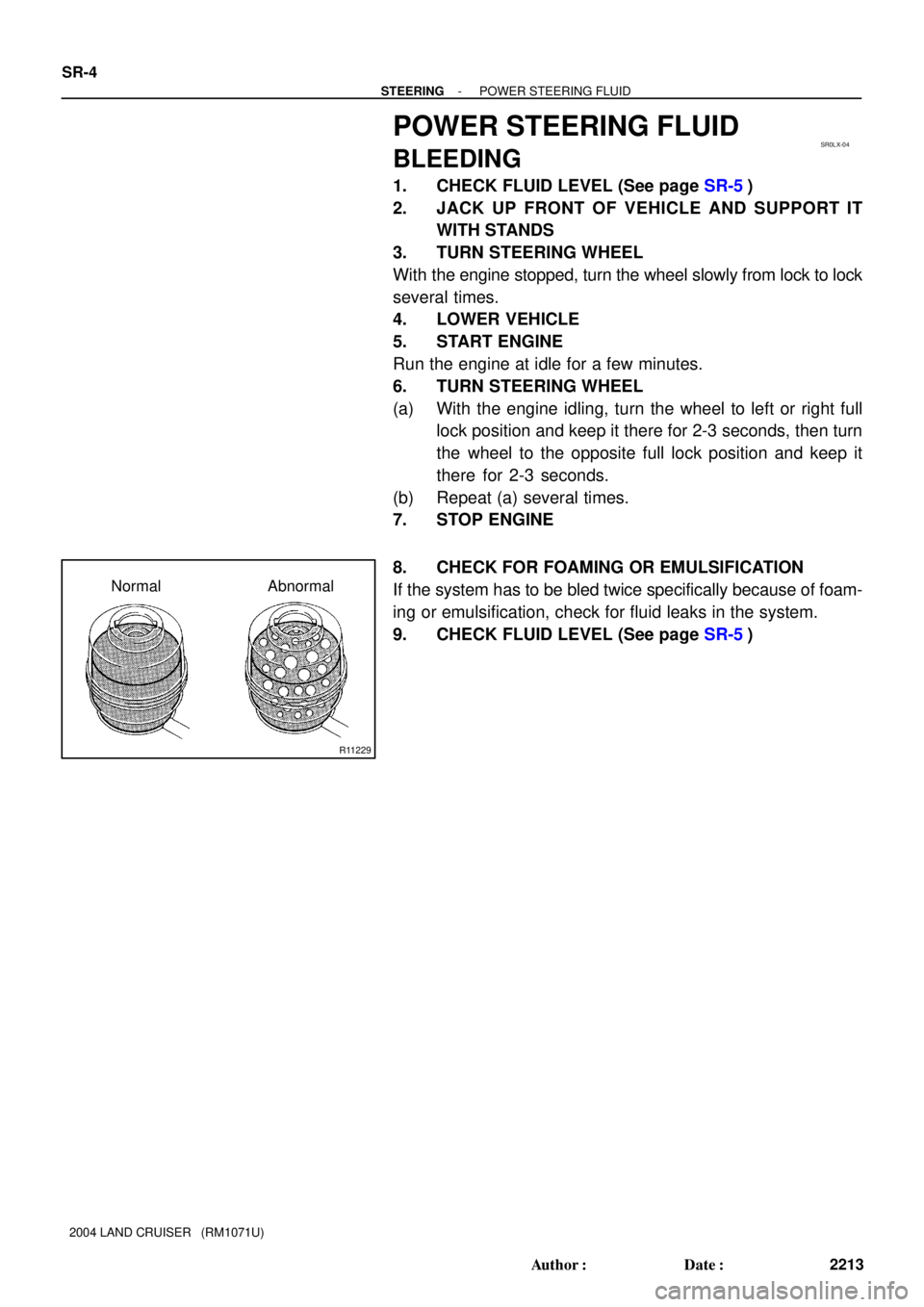
8. CHECK FOR FOAMING OR EMULSIFICATION
If the system has to be bled twice specifically because of foam-
ing or emulsification, check for fluid leaks in the system.
9. CHECK FLUID LEVEL (See page SR-5)
Page 2817 of 3115

or less
- STEERINGPOWER STEERING FLUID
SR-5
2214 Author�: Date�:
2004 LAND CRUISER (RM1071U)
INSPECTION
1. CH")
SR0LY-05
R00427
R11229
Normal
Abnormal
R11562Engine Idling
Engine Stopped 5 mm (0.2 in.)
or less
- STEERINGPOWER STEERING FLUID
SR-5
2214 Author�: Date�:
2004 LAND CRUISER (RM1071U)
INSPECTION
1. CHECK FLUID LEVEL
(a) Keep the vehicle level.
(b) With the engine stopped, check the fluid level in the oil
reservoir.
If necessary, add fluid.
Fluid: ATF DEXRON® II or III
HINT:
Check that the fluid level is within the HOT LEVEL range on the
reservoir.
If the fluid is cold, check that it is within the COLD LEVEL range.
(c) Start the engine and run it at idle.
(d) Turn the steering wheel from lock to lock several times to
boost fluid temperature.
Fluid temperature: 80°C (176°F)
(e) Check for foaming or emulsification.
If there is foaming or emulsification, bleed power steering sys-
tem (See page SR-4).
(f) With the engine idling, measure the fluid level in the oil
reservoir.
(g) Stop the engine.
(h) Wait a few minutes and remeasure the fluid level in the oil
reservoir.
Maximum fluid level rise: 5 mm (0.20 in.)
If a problem is found, bleed power steering system
(See page SR-4).
(i) Check the fluid level.
Page 2861 of 3115
R12473
SR0M0-06
F03748
- STEERINGSTEERING WHEEL
SR-9
2218 Author�: Date�:
2004 LAND CRUISER (RM1071U)
STEERING WHEEL
INSPECTION
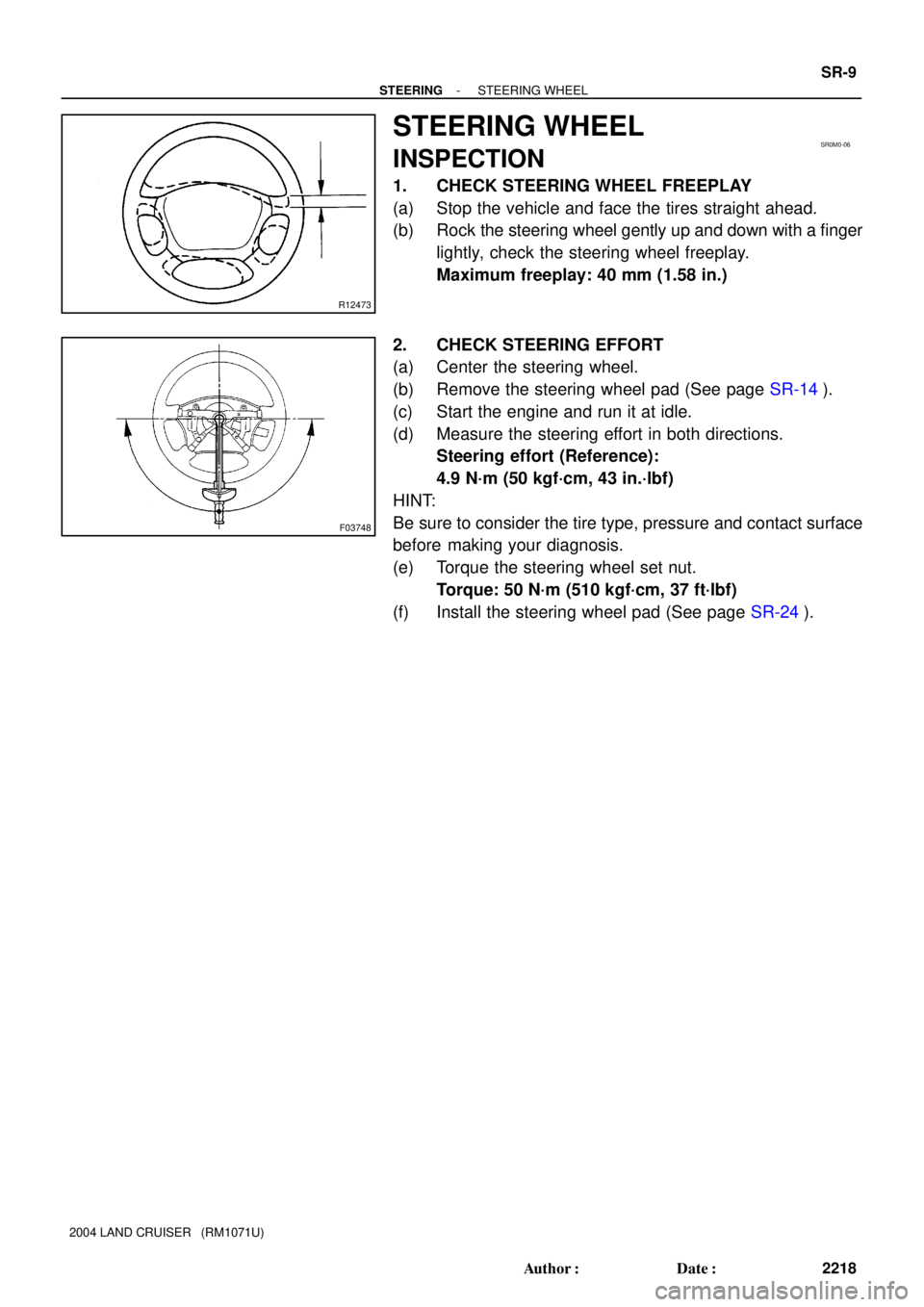
1. CHECK STEERING WHEEL FREEPLAY
(a) Stop the vehicle and face the tires straight ahead.
(b) Rock the steering wheel gently up and down with a finger
lightly, check the steering wheel freeplay.
Maximum freeplay: 40 mm (1.58 in.)
2. CHECK STEERING EFFORT
(a) Center the steering wheel.
(b) Remove the steering wheel pad (See page SR-14).
(c) Start the engine and run it at idle.
(d) Measure the steering effort in both directions.
Steering effort (Reference):
4.9 N´m (50 kgf´cm, 43 in.´lbf)
HINT:
Be sure to consider the tire type, pressure and contact surface
before making your diagnosis.
(e) Torque the steering wheel set nut.
Torque: 50 N´m (510 kgf´cm, 37 ft´lbf)
(f) Install the steering wheel pad (See page SR-24).
Page 2890 of 3115

DIFFERENTIAL LOCKING SYSTEM
ON-VEHICLE INSPECTION
1. INSPECT DI")
F05176
SA165-06
Z16659
M1 M2
- SUSPENSION AND AXLEDIFFERENTIAL LOCKING SYSTEM
SA-163
2113 Author�: Date�:
2004 LAND CRUISER (RM1071U)
DIFFERENTIAL LOCKING SYSTEM
ON-VEHICLE INSPECTION
1. INSPECT DIFFERENTIAL LOCK SYSTEM
(a) Inspect the indicator light.
Check that the indicator light lights up for approx. 1 se-
cond when the ignition switch is turned ON.
(b) Inspect the differential lock operation.
(1) Jack up the vehicle then start the engine.
(2) Shift the transfer shift lever to L position.
(3) When the diff. lock control switch is set to the RR
position, the indicator light is turned on.
Differential lock is applied to the rear wheel at this
time.
HINT:
If the gears of the differential lock system are not meshed, the
indicator light remains blinking, so rotate the tires to mesh the
gear.
(4) When the diff. lock control switch is at the OFF posi-
tion, the indicator light goes off.
Differential lock is released for the rear wheel at this
time.
(5) Check the voltage between the terminals of the rear
diff. lock control ECU when switching the diff. lock
control switch with the speedometer, registering
approx. 8 km/h (5 mph) or more.
Swith positionTerminalSpecified value
ONM1 - M20.5 V or less
(No change)
(6) Return the diff. lock control switch to OFF.
(7) Stop the engine and lower the vehicle.
2. INSPECT DIFF. LOCK SYSTEM CIRCUIT
(a) Inspect the battery positive voltage.
Battery positive voltage: 10 - 14 V