Page 817 of 3115
- DIAGNOSTICSABS & VEHICLE STABILITY CONTROL (VSC) &
BRAKE ASSIST (BA) SYSTEMDI-565
758 Author�: Date�:
2004 LAND CRUISER (RM1071U)
INSPECTION PROCEDURE
HINT:
Start the inspection from step1 in case of using the hand-held tester and start from step 2 in case of not using
the hand-held tester.
1 Check output value of the yaw rate (deceleration) sensor.
PREPARATION:
(a) Connect the hand-held tester to the DLC3.
(b) Turn the ignition switch ON and push the hand-held tester main switch ON.
(c) Select the DATALIST mode on the hand-held tester.
CHECK:
Check that the deceleration value of the deceleration sensor displayed on the hand-held tester is changing
when tilting the vehicle.
OK:
Deceleration value must be changing.
OK Check and replace skid control ECU.
NG
Page 823 of 3115

- DIAGNOSTICSABS & VEHICLE STABILITY CONTROL (VSC) &
BRAKE ASSIST (BA) SYSTEMDI-571
764 Author�: Date�:
2004 LAND CRUISER (RM1071U)
INSPECTION PROCEDURE
HINT:
Start the inspection from step 1 in case of using the hand-held tester and start from step 2 in case of not
using the hand-held tester.
1 Check output value of the master cylinder pressure sensor.
PREPARATION:
(a) Connect the hand-held tester to the DLC3.
(b) Turn the ignition switch ON and push the hand-held tester main switch ON.
(c) Select the DATA LIST mode on the hand-held tester.
CHECK:
Check that the brake fluid pressure value of the master cylinder pressure sensor displayed on the hand-held
tester is changing when depressing the brake pedal.
OK:
Brake fluid pressure value must be changing.
OK Go to step 4.
NG
2 Check master cylinder pressure sensor.
PREPARATION:
(a) Install the LSPV gauge to the front caliper bleeder plug portion, and bleed the LSPV gauge.
SST 09709-29018
(b) Remove the air cleaner inlet and battery clamp cover.
CHECK:
Start the engine and depress the brake pedal, then check the relation between the fluid pressure and voltage
of PMC and E2 terminals of the skid control ECU with connectors still connected.
OK:
Front brake caliper fluid pressureVoltage
0 kPa (0 Kgf/cm2, 0 psi)0.37 to 0.63 V
5,883 kPa (60 kgf/cm2, 853 psi)1.57 to 1.83 V
11,768 kPa (120 kgf/cm2, 1,706 psi)2.77 to 3.03 V
HINT:
Voltage between terminals VCM and E2: 4.7 to 5.3 V
NG Replace master cylinder pressure sensor.
OK
Page 855 of 3115

F09165
GND1GND2
IG1 GND3
GND4
(-)(+) ON
- DIAGNOSTICSABS & VEHICLE STABILITY CONTROL (VSC) &
BRAKE ASSIST (BA) SYSTEMDI-603
796 Author�: Date�:
2004 LAND CRUISER (RM1071U)
INSPECTION PROCEDURE
1 Check battery positive voltage.
OK:
Voltage: 10 to 14 V
NG Check and repair the charging system.
OK
2 Check voltage of the ECU IG power source.
In case of using the hand-held tester:
PREPARATION:
(a) Connect the hand-held tester to the DLC3.
(b) Turn the ignition switch ON and push the hand-held tester main switch ON.
(c) Select the DATA LIST mode on the hand-held tester.
CHECK:
Check the voltage condition output from the ECU displayed on the hand-held tester.
OK:
ºNormalº is displayed.
In case of not using the hand-held tester:
PREPARATION:
Remove the skid control ECU with connectors still connected.
CHECK:
(a) Turn the ignition switch ON.
(b) Measure voltage between terminals IG1 and GND of the
skid control ECU connector.
OK:
Voltage: 10 to 14 V
OK Turn ignition switch OFF, check and replace
skid control ECU.
NG
Page 870 of 3115

F04508
LOCK
12
12RH Side LH Side
2
4
4 2
- DIAGNOSTICSABS & VEHICLE STABILITY CONTROL (VSC) &
BRAKE ASSIST (BA) SYSTEMDI-617
810 Author�: Date�:
2004 LAND CRUISER (RM1071U)
INSPECTION PROCEDURE
HINT:
Start the inspection from step 1 in case of using the hand-held tester and start from step 2 in case of not
using the hand-held tester.
1 Check output value of speed sensor.
PREPARATION:
(a) Connect the hand-held tester to the DLC3.
(b) Turn the ignition switch ON and push the hand-held tester main switch ON.
(c) Select the DATALIST mode on the hand-held tester.
CHECK:
Check that there is no difference between the speed value output from the speed sensor displayed on the
hand-held tester and the speed value displayed on the speedometer when driving the vehicle.
OK:
There is almost no difference from the displayed speed value.
HINT:
There is tolerance of ± 10 % in the speedometer indication.
OK Go to step 4.
NG
2 Check speed sensor.
Front:
PREPARATION:
(a) Make sure that there is no looseness at the connector's
locking part and connecting part of the connector.
(b) Disconnect the speed sensor connector.
CHECK:
�LH side:
Measure resistance between terminals 2 and 4 of the
speed sensor connector.
�RH side:
Measure resistance between terminals 1 and 2 of the
speed sensor connector.
OK:
Resistance: 0.92 to 1.22 kW
CHECK:
�LH side:
Measure resistance between terminals 2 and 4 of the
speed sensor connector and body ground.
�RH side:
Measure resistance between terminals 1 and 2 of the
speed sensor connector and body ground.
Page 877 of 3115
F17760
J/B No. 7 D1
DLC1
Cowl Side J/B LH Cowl Side
J/B RHTC TC
E1
TC
CGA42 7D
7B 7D
IF
2D II EB3BP-B
W-BP-B P-B
W-B
W-B
W-B
1D7
DLC3
18
4 114
5
311
3
13ABS & BA & TRAC
& VSC ECU
- DIAGNOSTICSABS & VEHICLE STABILITY CONTROL (VSC) &
BRAKE ASSIST (BA) SYSTEMDI-651
844 Author�: Date�:
2004 LAND CRUISER (RM1071U)
Tc Terminal Circuit
CIRCUIT DESCRIPTION
Connecting terminals Tc and E1 of the DLC1 or Tc and CG of the DLC3 causes the ECU to display the DTC
by flashing the ABS warning light and VSC TRAC warning light.
WIRING DIAGRAM
DICAC-01
Page 893 of 3115

Inspector 's
Name:
Customer 's Name
Date Vehicle
Brought InRegistration DateRegistration No.
Frame No.
Odometer Reading/ /
/ /
Date Problem First Occurred
Frequency Problem Occurs/ /
ContinuousIntermittent ( times a day)
TRAC does not operate. (Wheels spin when starting rapidly.)
DisplaysDoes not display
DTC Check1st Time
2nd TimeNormal Code
Malfunction Code (Code )
Normal CodeMalfunction Code (Code )
Symptomskm
miles
Light Abnormal TRAC OFF Indicator
Light Abnormal SLIP Indicator
Remains ONDoes not light up
Check Item
NormalMalfunction Code (Code )
NormalMalfunction Code (Code )
ABS Warning Light
Malfunction
Indicator Light TRAC & VSC Check Sheet
Remains ONDoes not light up
VSC does not operate. (Wheels sideslip at the time of sharp turning.)
VSC TRC Warning
Indicator Abnormal
Skid Control
Buzzer AbnormalDoes not soundSounds
VSC/TRC OFF SW
SYSTEMFreeze Frame Data
SHIFT POSITION
YAW RATON
OFF
VSC/TRC
P, NR
D
deg/s
VFAIL
23
4L
MAS CYL PRESS
THROTTLE
MAS PRESS GRADE
G (RIGHT&LEFT)
G (BACK&FORTH)
STEERING ANG
deg
deg
MPa/s
G
G DI-504
- DIAGNOSTICSABS & VEHICLE STABILITY CONTROL (VSC) &
BRAKE ASSIST (BA) SYSTEM
697 Author�: Date�:
2004 LAND CRUISER (RM1071U)
Page 894 of 3115

DIC8V-01
DI-518- DIAGNOSTICSABS & VEHICLE STABILITY CONTROL (VSC) &
BRAKE ASSIST (BA) SYSTEM
711 Author�: Date�:
2004 LAND CRUISER (RM1071U)
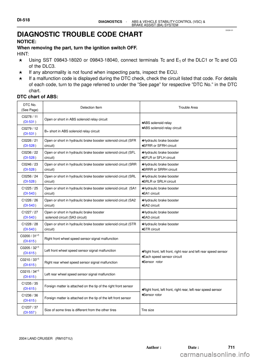
DIAGNOSTIC TROUBLE CODE CHART
NOTICE:
When removing the part, turn the ignition switch OFF.
HINT:
�Using SST 09843-18020 or 09843-18040, connect terminals Tc and E1 of the DLC1 or Tc and CG
of the DLC3.
�If any abnormality is not found when inspecting parts, inspect the ECU.
�If a malfunction code is displayed during the DTC check, check the circuit listed that code. For details
of each code, turn to the page referred to under the ºSee pageº for respective ºDTC No.º in the DTC
chart.
DTC chart of ABS:
DTC No.
(See Page)Detection ItemTrouble Area
C0278 / 11
(DI-531)Open or short in ABS solenoid relay circuit�ABS solenoid relay
C0279 / 12
(DI-531)B+ short in ABS solenoid relay circuit
�ABS solenoid relay
�ABS solenoid relay circuit
C0226 / 21
(DI-528)Open or short in hydraulic brake booster solenoid circuit (SFR
circuit)�Hydraulic brake booster
�SFRR or SFRH circuit
C0236 / 22
(DI-528)Open or short in hydraulic brake booster solenoid circuit (SFL
circuit)�Hydraulic brake booster
�SFLR or SFLH circuit
C0246 / 23
(DI-528)Open or short in hydraulic brake booster solenoid circuit (SRR
circuit)�Hydraulic brake booster
�SRRR or SRRH circuit
C0256 / 24
(DI-528)Open or short in hydraulic brake booster solenoid circuit (SRL
circuit)�Hydraulic brake booster
�SRLR or SRLH circuit
C1225 / 25
(DI-543)Open or short in hydraulic brake booster solenoid circuit (SA1
circuit)�Hydraulic brake booster
�SA1 circuit
C1226 / 26
(DI-543)Open or short in hydraulic brake booster solenoid circuit (SA2
circuit)�Hydraulic brake booster
�SA2 circuit
C1227 / 27
(DI-543)Open or short in hydraulic brake booster
solenoid circuit (SA3 circuit)�Hydraulic brake booster
�SA3 circuit
C1228 / 28
(DI-543)Open or short in hydraulic brake booster solenoid circuit (STR
circuit)�Hydraulic brake booster
�STR circuit
C0200 / 31*1
(DI-615)Right front wheel speed sensor signal malfunction
C0205 / 32*1
(DI-615)Left front wheel speed sensor signal malfunction�Right front, left front, right rear and left rear speed sensor
Eh d i itC0210 / 33*1
(DI-615)Right rear wheel speed sensor signal malfunction
�Each speed sensor circuit
�Sensor rotor
C0215 / 34*1
(DI-615)Left rear wheel speed sensor signal malfunction
C1235 / 35
(DI-615)Foreign matter is attached on the tip of the right front sensor�Right front, left front, right rear, left rear speed sensor
C1236 / 36
(DI-615)Foreign matter is attached on the tip of the left front sensor
�Right front, left front, right rear, left rear s eed sensor
�Sensor rotor
C1237 / 37
(DI-557)Size of some tires is different from the other tiresTire size
Page 901 of 3115

R01346
Normal Code
0.25 sec.
0.25 sec. 2 sec.
ON
OFF
ON
OFF0.5 sec. 0.5 sec.
Code 11 and 21
4 sec.1.5 sec.
2.5 sec.
Code 11 Code 21
F06425
Hand-held
Tester
DLC3
F05576
DI-506- DIAGNOSTICSABS & VEHICLE STABILITY CONTROL (VSC) &
BRAKE ASSIST (BA) SYSTEM
699 Author�: Date�:
2004 LAND CRUISER (RM1071U)
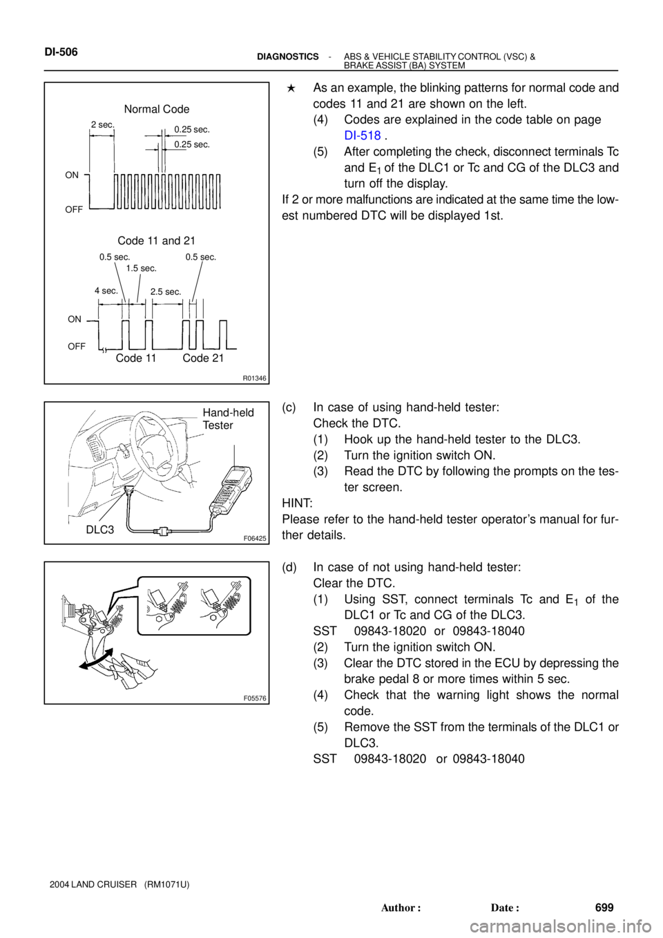
�As an example, the blinking patterns for normal code and
codes 11 and 21 are shown on the left.
(4) Codes are explained in the code table on page
DI-518.
(5) After completing the check, disconnect terminals Tc
and E
1 of the DLC1 or Tc and CG of the DLC3 and
turn off the display.
If 2 or more malfunctions are indicated at the same time the low-
est numbered DTC will be displayed 1st.
(c) In case of using hand-held tester:
Check the DTC.
(1) Hook up the hand-held tester to the DLC3.
(2) Turn the ignition switch ON.
(3) Read the DTC by following the prompts on the tes-
ter screen.
HINT:
Please refer to the hand-held tester operator's manual for fur-
ther details.
(d) In case of not using hand-held tester:
Clear the DTC.
(1) Using SST, connect terminals Tc and E
1 of the
DLC1 or Tc and CG of the DLC3.
SST 09843-18020 or 09843-18040
(2) Turn the ignition switch ON.
(3) Clear the DTC stored in the ECU by depressing the
brake pedal 8 or more times within 5 sec.
(4) Check that the warning light shows the normal
code.
(5) Remove the SST from the terminals of the DLC1 or
DLC3.
SST 09843-18020 or 09843-18040