Page 747 of 3115

CO0J2-03
B08321
B04475
B08320
- COOLINGRADIATOR
CO-19
1780 Author�: Date�:
2004 LAND CRUISER (RM1071U)
INSTALLATION
1. INSTALL SIDE SUPPORTS TO RADIATOR
(a) Install the 2 side support with 8 nuts.
Torque: 12.7 N´m (130 kgf´cm, 9 ft´lbf)
(b) Install the 2 brackets with the 4 nuts.
Torque: 20 N´m (200 kgf´cm, 13 ft´lbf)
2. INSTALL RADIATOR ASSEMBLY
(a) Place the radiator assembly to the body.
(b) Install the 2 nuts.
Torque: 20 N´m (200 kgf´cm, 15 ft´lbf)
(c) Install the radiator assembly with the 2 bolts to the body.
Torque: 18 N´m (185 kgf´cm, 13 ft´lbf)
3. INSTALL FAN PULLEY, FAN SHROUD, FAN WITH
FLUID COUPLING AND GENERATOR DRIVE BELT
(a) Place the fan with fluid coupling, fan pulley and fan shroud
in position.
(b) Temporarily install the fan pulley mounting nuts.
(c) Install the fan shroud with the 3 bolts.
Torque: 5.0 N´m (50 kgf´cm, 43 in.´lbf)
(d) Connect the A/T oil cooler hoses to the clamp on the fan
shroud.
(e) Install the generator drive belt. (See page CH-16)
(f) Tighten the 4 fan pulley mounting nuts.
(g) Install the 2 brackets on wire to the radiator wire with 2
bolts.
(h) Install the 2 clamps on the A/C discharge tube to the
brackets on the wire with the 2 nuts.
4. INSTALL RADIATOR RESERVOIR
(a) Install the grommet to the reservoir.
(b) Attach the lower side of the reservoir to the fun shuroud.
(c) install the reservoir with the 2 bolts.
(d) Connect the reservoir hose to the radiator.
(e) Install the clamp on the wire to the radiator.
5. CONNECT A/T OIL COOLER HOSES TO RADIATOR
6. CONNECT RADIATOR UPPER HOSE TO RADIATOR
7. CONNECT RADIATOR LOWER HOSE TO RADIATOR
8. FILL WITH ENGINE COOLANT
9. START ENGINE AND CHECK FOR ENGINE COOLANT
LEAKS
10. RECHECK ENGINE COOLANT LEVEL
Page 751 of 3115
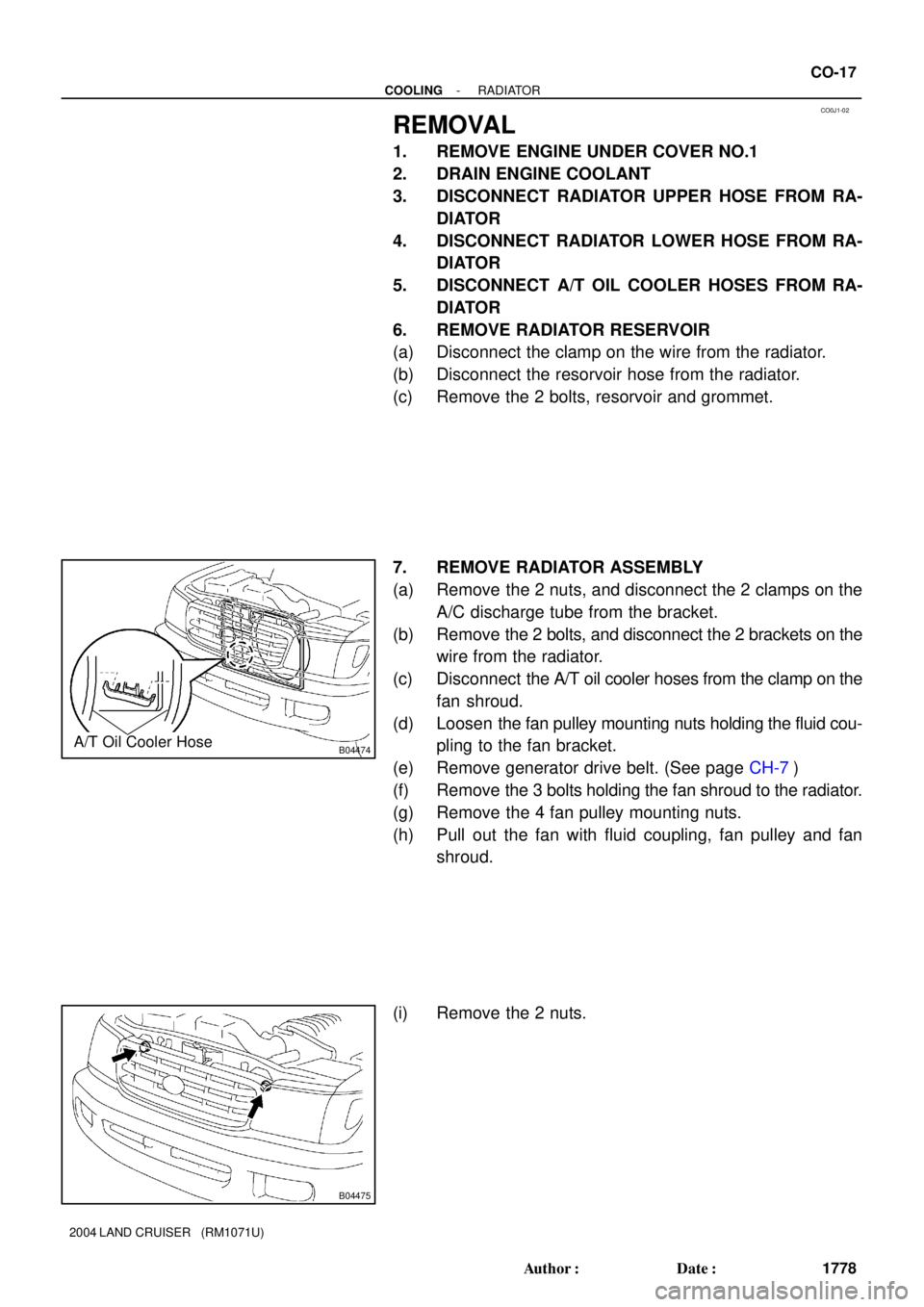
CO0J1-02
B04474A/T Oil Cooler Hose
B04475
- COOLINGRADIATOR
CO-17
1778 Author�: Date�:
2004 LAND CRUISER (RM1071U)
REMOVAL
1. REMOVE ENGINE UNDER COVER NO.1
2. DRAIN ENGINE COOLANT
3. DISCONNECT RADIATOR UPPER HOSE FROM RA-
DIATOR
4. DISCONNECT RADIATOR LOWER HOSE FROM RA-
DIATOR
5. DISCONNECT A/T OIL COOLER HOSES FROM RA-
DIATOR
6. REMOVE RADIATOR RESERVOIR
(a) Disconnect the clamp on the wire from the radiator.
(b) Disconnect the resorvoir hose from the radiator.
(c) Remove the 2 bolts, resorvoir and grommet.
7. REMOVE RADIATOR ASSEMBLY
(a) Remove the 2 nuts, and disconnect the 2 clamps on the
A/C discharge tube from the bracket.
(b) Remove the 2 bolts, and disconnect the 2 brackets on the
wire from the radiator.
(c) Disconnect the A/T oil cooler hoses from the clamp on the
fan shroud.
(d) Loosen the fan pulley mounting nuts holding the fluid cou-
pling to the fan bracket.
(e) Remove generator drive belt. (See page CH-7)
(f) Remove the 3 bolts holding the fan shroud to the radiator.
(g) Remove the 4 fan pulley mounting nuts.
(h) Pull out the fan with fluid coupling, fan pulley and fan
shroud.
(i) Remove the 2 nuts.
Page 757 of 3115
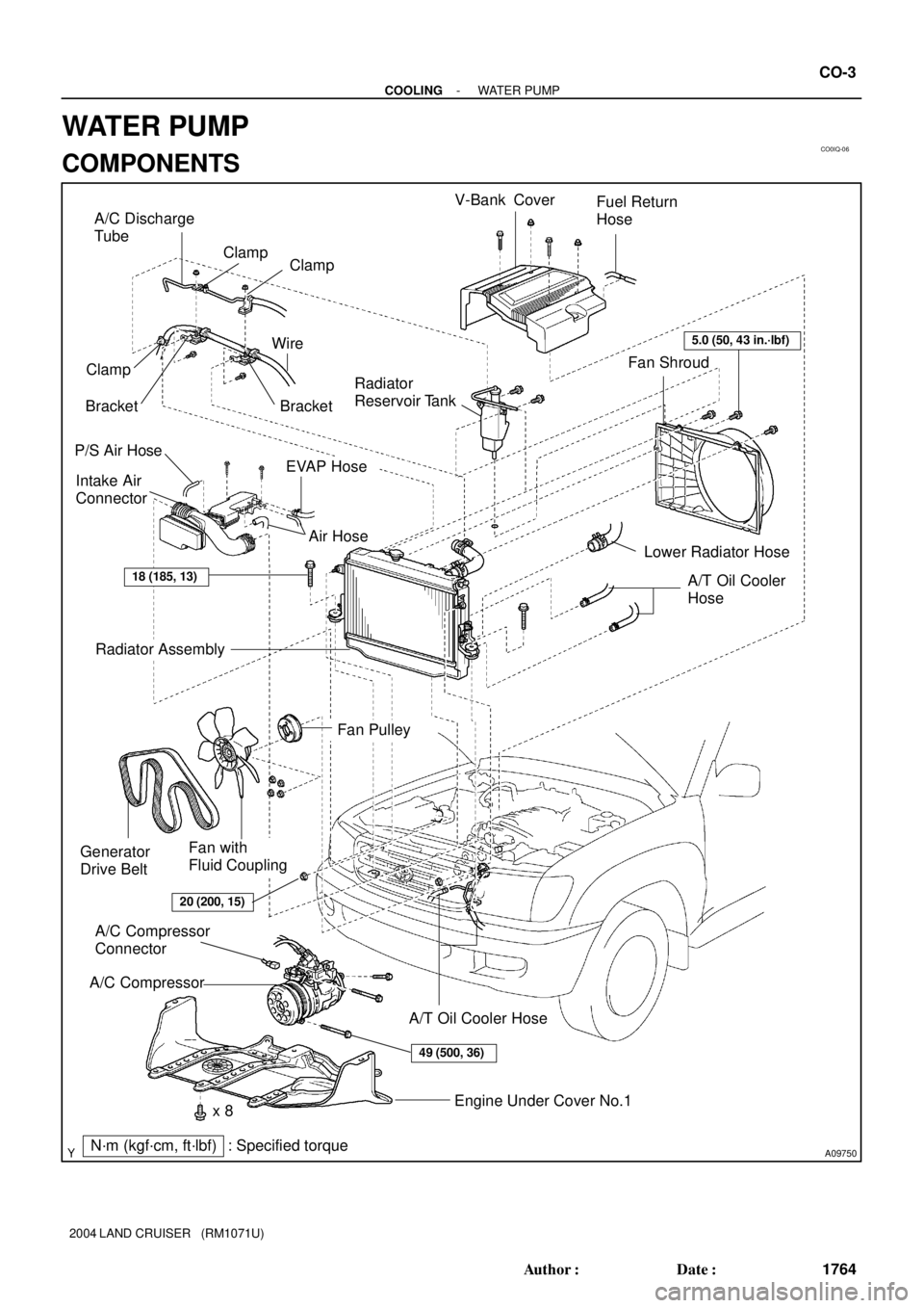
CO0IQ-06
A09750
P/S Air HoseRadiator
Reservoir Tank
Intake Air
Connector
Radiator Assembly
EVAP HoseV-Bank Cover
Engine Under Cover No.1
N´m (kgf´cm, ft´lbf) : Specified torque Generator
Drive Belt
A/C CompressorA/C Compressor
Connector
A/T Oil Cooler Hose
Fan with
Fluid Coupling
Fan Pulley
49 (500, 36)
5.0 (50, 43 in.´lbf)
18 (185, 13)
Air Hose
x 8Fan Shroud Fuel Return
Hose
20 (200, 15)
A/T Oil Cooler
Hose
A/C Discharge
Tube
Clamp
Bracket WireClamp
Clamp
Lower Radiator Hose
Bracket
- COOLINGWATER PUMP
CO-3
1764 Author�: Date�:
2004 LAND CRUISER (RM1071U)
WATER PUMP
COMPONENTS
Page 758 of 3115
B04470
RH No.3 Timing Belt Cover
LH No.3 Timing Belt CoverNo.2 Timing Belt Cover
Camshaft Position
Sensor Connector
Engine Wire
Oil Cooler Pipe
Timing Belt
Fan Bracket Drive Belt Timing Pulley
Timing Belt Tensioner Dust Boot
N´m (kgf´cm, ft´lbf) : Specified torqueCover Plate
7.5 (80, 66 in.´lbf)
16 (160, 12)
39 (400,29)
245 (2,500, 181)
32 (330, 24)
16 (160, 12)
7.5 (80, 66 in.´lbf)
Water Bypass
Hose
CO-4
- COOLINGWATER PUMP
1765 Author�: Date�:
2004 LAND CRUISER (RM1071U)
Page 1004 of 3115

- DIAGNOSTICSAUTOMATIC TRANSMISSION
DI-483
676 Author�: Date�:
2004 LAND CRUISER (RM1071U)
DTC P2740 Transmission Fluid Temperature Sensor ºBº
Circuit
DTC P2742 Transmission Fluid Temperature Sensor ºBº
Circuit Low Input
DTC P2743 Transmission Fluid Temperature Sensor ºBº
Circuit High Input
CIRCUIT DESCRIPTION
The ATF temperature sensor converts fluid temperature into a resistance value which is input in to the ECM.
ATF temperature sensor No.2 is on the transmission and just before the oil cooler inlet pipeline.
If ECM detects the abnormally high temperature of ATF by this sensor, it draws driver's attention by illuminat-
ing the warning lamp.
HINT:
�The temperature of ATF easily raises when towing, climbing hills and in traffic, etc.
�If the ATF temperature sensor No.2 shorts, the signal that indicates the ATF temperature is 150�C
(302�F) or higher is input in ECM.
Vehicle conditions when sensor is in normal and when the vehicle is in short are indicated in the table
below.
ATF temperature No.2 Sensor
StateDetection ConditionSymptomRecovery Condition
Sensor is normal
�AT fluid temp. more than 150�C
(302�F).�AT Oil Temp. warning light re-
mains on�AT fluid temp. less than 135�C
(275�F). *1
Sensor is normal�AT fluid temp. more than 130�C
(266�F).�Shift point too high.�AT fluid temp. less than 110�C
(230�F).
Sensor is in short�Any conditions.
�AT Oil Temp. warning light re-
mains on
�Shift point too high.
�Symptoms still occur
HINT:
*1: When AT fluid temperature is in normal range, it decreases to less than 135�C within 5 minutes with the
shift lever in P or N position in a idling state.
DTC No.DTC Detecting ConditionTrouble Area
P2740
(a) and (b) is detected momentary within 0.5 sec. when neither
P2742 or P2743 is not detected (1-trip detection logic)
(a) ATF temperature sensor resistance is less than 79 W.
(b) ATF temperature sensor resistance is more than 156 kW.
HINT:
Wthin 0.5 sec. the malfunction switches from (a) to (b) or from
(b) to (a)
�Open or short in ATF temperature sensor No. 2 circuit
�ATF temperature sensor No. 2
P2742ATF temperature sensor resistance is less than 79 W. for 0.5
sec. or more (1-trip detection logic)�ECM
P2743
DTC is detected for 0.5 sec. or more (1-trip detection logic)
ATF temperature sensor resistance is more than 156 kW. after
started engine for 15 minutes or more
DIC33-01
Page 1795 of 3115
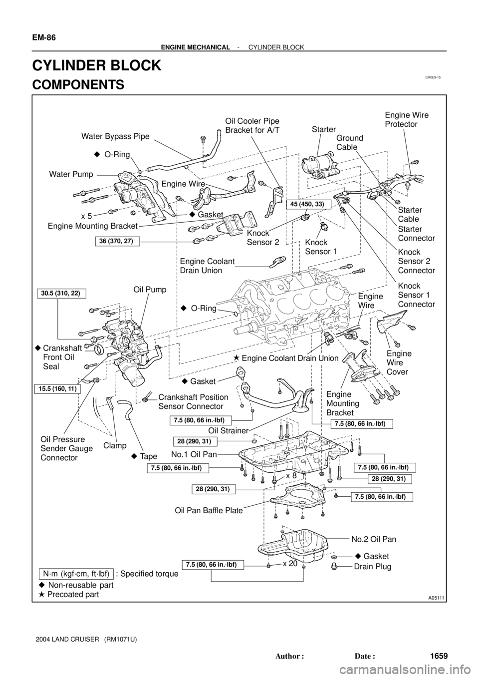
EM0E9-15
A05111
Engine Mounting Bracket
Oil Pump
Crankshaft
Front Oil
Seal
Crankshaft Position
Sensor Connector
No.1 Oil Pan
Drain Plug
� Non-reusable part
� Precoated partEngine Wire
Oil StrainerEngine
Mounting
BracketStarter
Cable
Knock
Sensor 2
Connector Knock
Sensor 1Knock
Sensor 2
Engine Coolant Drain UnionStarter
No.2 Oil Pan Oil Pan Baffle Platex 8 Water Pump
� Gasket � O-Ring
Engine
Wire
Engine
Wire
CoverKnock
Sensor 1
Connector Engine Coolant
Drain Union
45 (450, 33)
36 (370, 27)
30.5 (310, 22)
15.5 (160, 11)
28 (290, 31)
x 5
Oil Pressure
Sender Gauge
Connector
7.5 (80, 66 in.´lbf)
7.5 (80, 66 in.´lbf)
7.5 (80, 66 in.´lbf)
N´m (kgf´cm, ft´lbf) : Specified torque �
�
x 20
Ground
Cable
Clamp
Engine Wire
Protector
� Tape
28 (290, 31)
� Gasket
7.5 (80, 66 in.´lbf)
28 (290, 31)
7.5 (80, 66 in.´lbf)
Water Bypass Pipe
Oil Cooler Pipe
Bracket for A/T
7.5 (80, 66 in.´lbf)
� O-Ring
Starter
Connector
� Gasket
EM-86
- ENGINE MECHANICALCYLINDER BLOCK
1659 Author�: Date�:
2004 LAND CRUISER (RM1071U)
CYLINDER BLOCK
COMPONENTS
Page 1797 of 3115
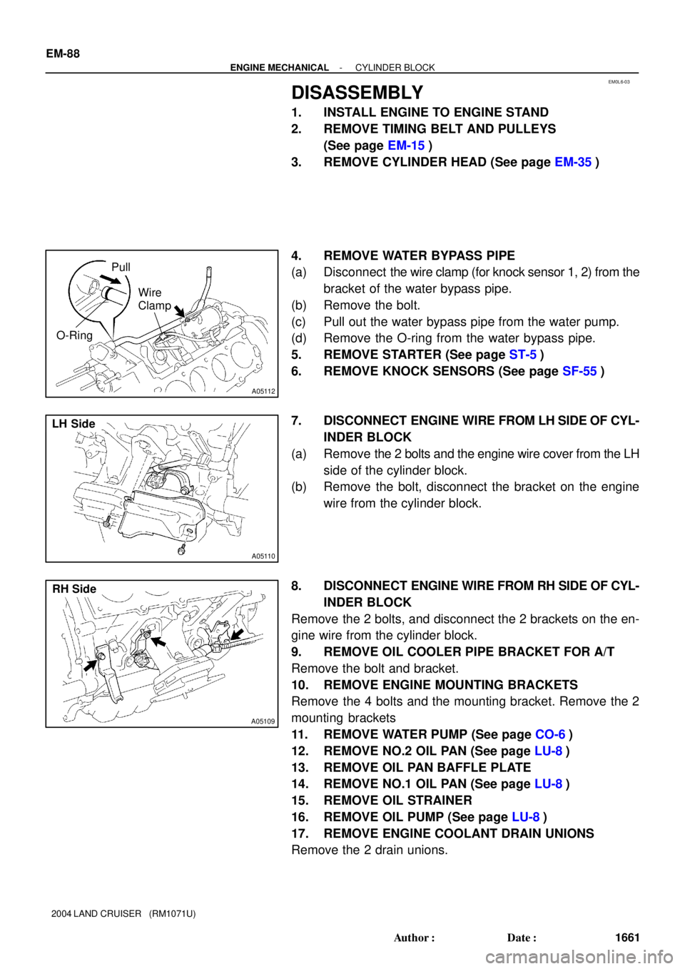
EM0L6-03
A05112
Pull
Wire
Clamp
O-Ring
A05110
LH Side
A05109
RH Side EM-88
- ENGINE MECHANICALCYLINDER BLOCK
1661 Author�: Date�:
2004 LAND CRUISER (RM1071U)
DISASSEMBLY
1. INSTALL ENGINE TO ENGINE STAND
2. REMOVE TIMING BELT AND PULLEYS
(See page EM-15)
3. REMOVE CYLINDER HEAD (See page EM-35)
4. REMOVE WATER BYPASS PIPE
(a) Disconnect the wire clamp (for knock sensor 1, 2) from the
bracket of the water bypass pipe.
(b) Remove the bolt.
(c) Pull out the water bypass pipe from the water pump.
(d) Remove the O-ring from the water bypass pipe.
5. REMOVE STARTER (See page ST-5)
6. REMOVE KNOCK SENSORS (See page SF-55)
7. DISCONNECT ENGINE WIRE FROM LH SIDE OF CYL-
INDER BLOCK
(a) Remove the 2 bolts and the engine wire cover from the LH
side of the cylinder block.
(b) Remove the bolt, disconnect the bracket on the engine
wire from the cylinder block.
8. DISCONNECT ENGINE WIRE FROM RH SIDE OF CYL-
INDER BLOCK
Remove the 2 bolts, and disconnect the 2 brackets on the en-
gine wire from the cylinder block.
9. REMOVE OIL COOLER PIPE BRACKET FOR A/T
Remove the bolt and bracket.
10. REMOVE ENGINE MOUNTING BRACKETS
Remove the 4 bolts and the mounting bracket. Remove the 2
mounting brackets
11. REMOVE WATER PUMP (See page CO-6)
12. REMOVE NO.2 OIL PAN (See page LU-8)
13. REMOVE OIL PAN BAFFLE PLATE
14. REMOVE NO.1 OIL PAN (See page LU-8)
15. REMOVE OIL STRAINER
16. REMOVE OIL PUMP (See page LU-8)
17. REMOVE ENGINE COOLANT DRAIN UNIONS
Remove the 2 drain unions.
Page 1819 of 3115
A04856
FrontPort
A05110
LH Side
A05109
RH Side
A05132
Push
Wire
Clamp
New
O-Ring
- ENGINE MECHANICALCYLINDER BLOCK
EM-1 13
1686 Author�: Date�:
2004 LAND CRUISER (RM1071U)
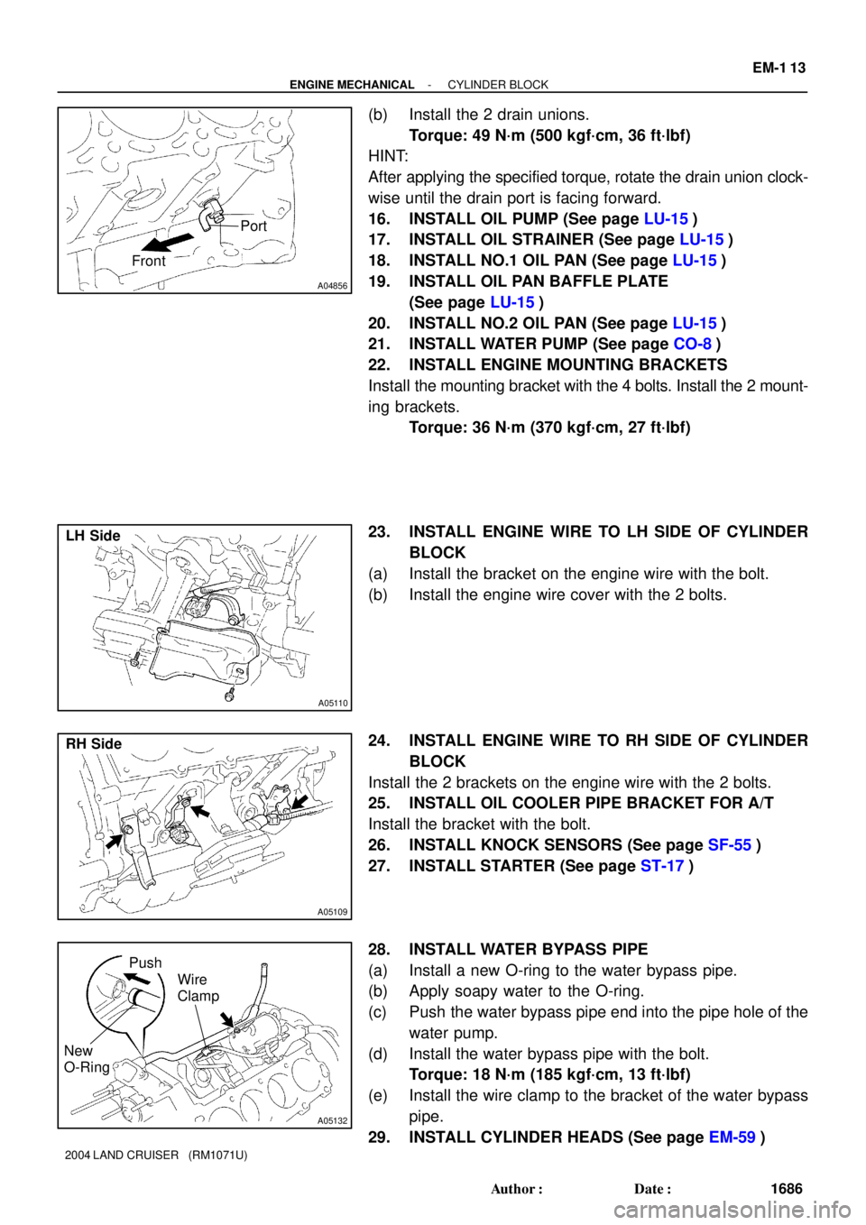
(b) Install the 2 drain unions.
Torque: 49 N´m (500 kgf´cm, 36 ft´lbf)
HINT:
After applying the specified torque, rotate the drain union clock-
wise until the drain port is facing forward.
16. INSTALL OIL PUMP (See page LU-15)
17. INSTALL OIL STRAINER (See page LU-15)
18. INSTALL NO.1 OIL PAN (See page LU-15)
19. INSTALL OIL PAN BAFFLE PLATE
(See page LU-15)
20. INSTALL NO.2 OIL PAN (See page LU-15)
21. INSTALL WATER PUMP (See page CO-8)
22. INSTALL ENGINE MOUNTING BRACKETS
Install the mounting bracket with the 4 bolts. Install the 2 mount-
ing brackets.
Torque: 36 N´m (370 kgf´cm, 27 ft´lbf)
23. INSTALL ENGINE WIRE TO LH SIDE OF CYLINDER
BLOCK
(a) Install the bracket on the engine wire with the bolt.
(b) Install the engine wire cover with the 2 bolts.
24. INSTALL ENGINE WIRE TO RH SIDE OF CYLINDER
BLOCK
Install the 2 brackets on the engine wire with the 2 bolts.
25. INSTALL OIL COOLER PIPE BRACKET FOR A/T
Install the bracket with the bolt.
26. INSTALL KNOCK SENSORS (See page SF-55)
27. INSTALL STARTER (See page ST-17)
28. INSTALL WATER BYPASS PIPE
(a) Install a new O-ring to the water bypass pipe.
(b) Apply soapy water to the O-ring.
(c) Push the water bypass pipe end into the pipe hole of the
water pump.
(d) Install the water bypass pipe with the bolt.
Torque: 18 N´m (185 kgf´cm, 13 ft´lbf)
(e) Install the wire clamp to the bracket of the water bypass
pipe.
29. INSTALL CYLINDER HEADS (See page EM-59)