Page 2611 of 3115

SS0OK-05
SS-38
- SERVICE SPECIFICATIONSSUSPENSION AND AXLE
178 Author�: Date�:
2004 LAND CRUISER (RM1071U)
TORQUE SPECIFICATION
FRONT
Part tightenedN´mkgf´cmft´lbf
Hub bolt1311,34097
Knuckle stopper bolt lock nut4445032
Steering knuckle x Brake caliper1231,25091
Disc x Axle hub7475055
Flange x Axle hub3333524
Axle hub bearing lock nut6465047
Flexible hose x Bracket2829021
ABS speed sensor installation bolt8.08271 in.´lbf
ABS speed sensor wire harness x Steering knuckle arm1313010
ABS speed sensor wire harness bracket x Steering knuckle2829021
Steering knuckle arm x Steering knuckle1471,500108
Tie rod end x Steering knuckle arm1221,25090
Upper suspension arm x Steering knuckle11 01,12581
Lower suspension arm x Steering knuckle1591,62511 7
Oil seal x Steering knuckle1818513
Propeller shaft x Companion flange8082059
Body x No. 3 frame crossmember6869550
No. 3 frame crossmember x Differential support1861,900137
Differential support x Differential tube1861,900137
Differential support x Differential carrier7880058
Differential support x Body1861,900137
Differential carrier cover x Body1861,900137
Breather hose bracket x Carrier cover1717313
Filler plug4950036
Drain plug4950036
Differential tube x Differential carrier1051,07077
Bearing cap x Differential carrier8587063
Oil deflector x Carrier cover7.37465 in.´lbf
Carrier cover x Differential carrier4747535
Differential case x Ring gear9798572
Companion flange x Drive pinionSee page SA-47
Lower suspension arm x Shock absorber1351,400100
Piston rod x Body6870050
Torque arm x Lower suspension arm2252,300166
ABS speed sensor wire harness x Upper suspension arm1313010
Upper suspension arm x Body981,00072
Stabilizer bar link x Lower suspension arm5253038
Lower suspension arm x Body2302,350170
Stabilizer bar x Stabilizer bar link2525018
Stabilizer bar bracket x Body1818513
Page 2904 of 3115
F11449
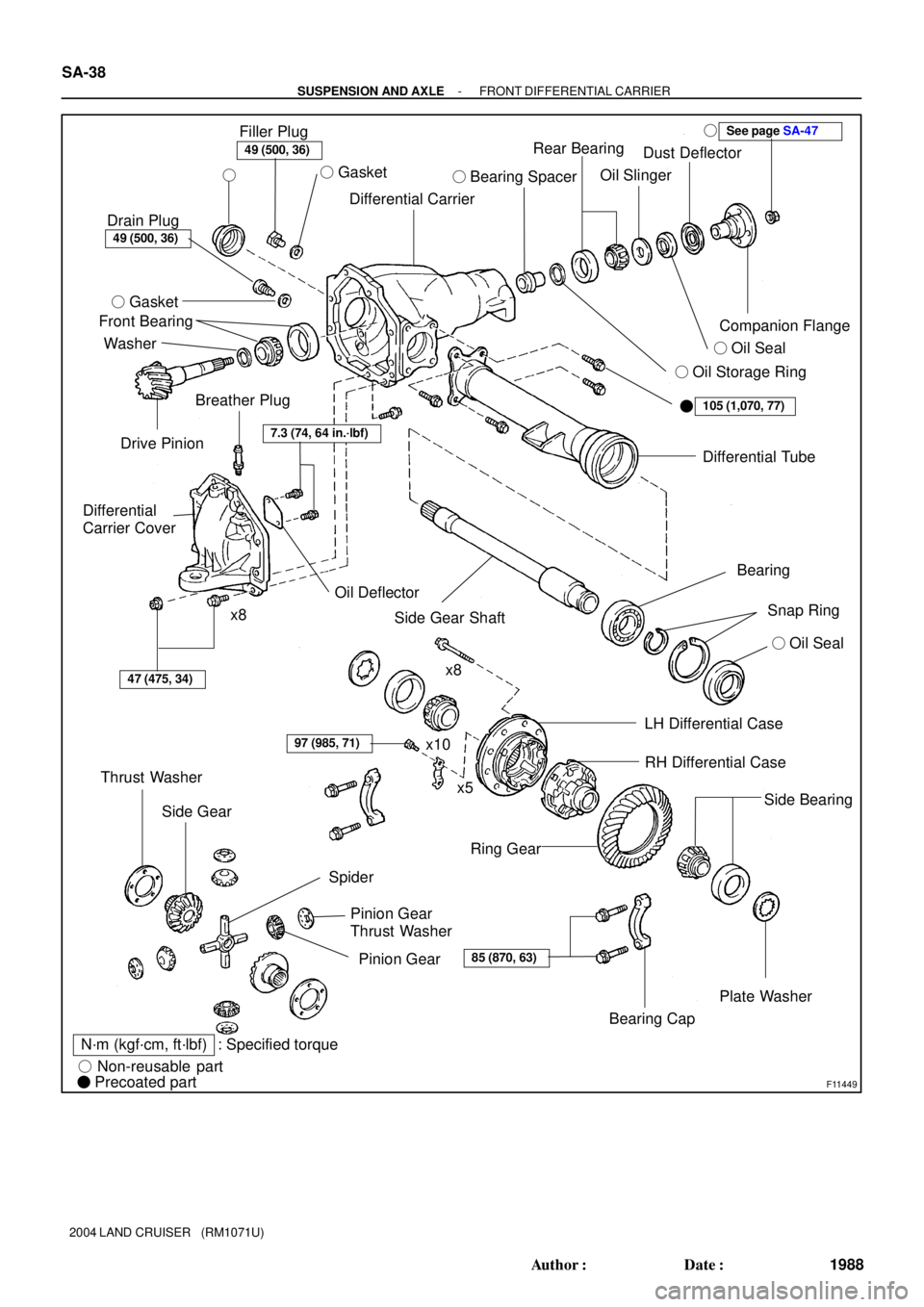
Rear Bearing
Oil Slinger
Companion Flange
See page SA-47�
� Oil Seal � Bearing Spacer
� Oil Storage Ring Dust Deflector
�
105 (1,070, 77)
Differential Tube
49 (500, 36)
Filler Plug
� Gasket
49 (500, 36)
Drain Plug
� Gasket
WasherDifferential Carrier �
Drive Pinion Front Bearing
Breather Plug
Oil Deflector7.3 (74, 64 in.´lbf)
Differential
Carrier Cover
47 (475, 34)
x8
Thrust Washer
Side Gear
Spider
Pinion Gear
Thrust Washer
Pinion Gear
N´m (kgf´cm, ft´lbf) : Specified torque
� Non-reusable part
� Precoated part
Side Gear ShaftBearing
Snap Ring
� Oil Seal
x10
x5LH Differential Case
Ring Gear
Plate Washer
Bearing Cap
85 (870, 63)
97 (985, 71)
x8
Side Bearing
RH Differential Case
SA-38
- SUSPENSION AND AXLEFRONT DIFFERENTIAL CARRIER
1988 Author�: Date�:
2004 LAND CRUISER (RM1071U)
Page 2906 of 3115
SA2352
F05221
SST
F05222
SST
F05223
SST
- SUSPENSION AND AXLEFRONT DIFFERENTIAL CARRIER
SA-41
1991 Author�: Date�:
2004 LAND CRUISER (RM1071U)
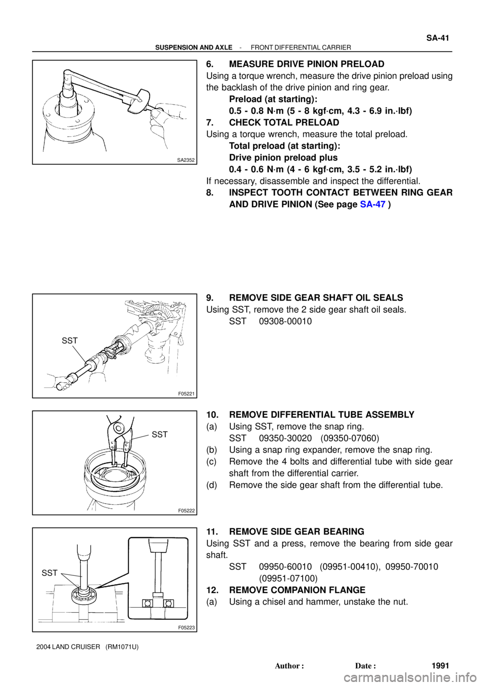
6. MEASURE DRIVE PINION PRELOAD
Using a torque wrench, measure the drive pinion preload using
the backlash of the drive pinion and ring gear.
Preload (at starting):
0.5 - 0.8 N´m (5 - 8 kgf´cm, 4.3 - 6.9 in.´lbf)
7. CHECK TOTAL PRELOAD
Using a torque wrench, measure the total preload.
Total preload (at starting):
Drive pinion preload plus
0.4 - 0.6 N´m (4 - 6 kgf´cm, 3.5 - 5.2 in.´lbf)
If necessary, disassemble and inspect the differential.
8. INSPECT TOOTH CONTACT BETWEEN RING GEAR
AND DRIVE PINION (See page SA-47)
9. REMOVE SIDE GEAR SHAFT OIL SEALS
Using SST, remove the 2 side gear shaft oil seals.
SST 09308-00010
10. REMOVE DIFFERENTIAL TUBE ASSEMBLY
(a) Using SST, remove the snap ring.
SST 09350-30020 (09350-07060)
(b) Using a snap ring expander, remove the snap ring.
(c) Remove the 4 bolts and differential tube with side gear
shaft from the differential carrier.
(d) Remove the side gear shaft from the differential tube.
11. REMOVE SIDE GEAR BEARING
Using SST and a press, remove the bearing from side gear
shaft.
SST 09950-60010 (09951-00410), 09950-70010
(09951-07100)
12. REMOVE COMPANION FLANGE
(a) Using a chisel and hammer, unstake the nut.
Page 2912 of 3115

SA14P-09
SA1978
SA1976
FA2037
Matchmarks
- SUSPENSION AND AXLEFRONT DIFFERENTIAL CARRIER
SA-47
1997 Author�: Date�:
2004 LAND CRUISER (RM1071U)
REASSEMBLY
HINT:
�Using a shop rag, clean off any foreign object from the
parts.
�Apply all of the sliding and rotating surfaces with hypoid
gear oil.
1. MEASURE SIDE GEAR BACKLASH AND ASSEMBLE
DIFFERENTIAL CASE
(a) Install the 2 side gear thrust washers to the side gears.
(b) Install the 2 side gears to the RH case.
(c) Install the 4 pinion gears and pinion gear thrust washers
to the spider.
(d) Install the pinion gears with the spider to the RH case.
(e) Using a dial indicator, holding the side gear and spider,
measure the side gear backlash,
Backlash: 0.05 - 0.20 mm (0.0020 - 0.0079 in.)
HINT:
�Measure at all 4 locations.
�Measure the backlash at the RH case and at the LH case.
If the backlash is not within the specification, install a thrust
washer of a different thickness.
Thrust washer thickness
Thickness mm (in.)Thickness mm (in.)
0.9 (0.035)1.2 (0.047)
1.0 (0.039)1.3 (0.051)
1.1 (0.043)-
(f) Align the matchmarks on the LH and RH cases.
(g) Torque the 8 bolts uniformly a little at a time.
Torque: 47 N´m (480 kgf´cm, 35 ft´lbf)
Page 2922 of 3115
F05214
SST
F05222
SST
F05215
SST
- SUSPENSION AND AXLEFRONT DIFFERENTIAL CARRIER
SA-57
2007 Author�: Date�:
2004 LAND CRUISER (RM1071U)
23. RECHECK TOTAL PRELOAD (See page SA-40)
24. RECHECK RING GEAR BACKLASH
(See page SA-40)
25. RECHECK TOOTH CONTACT BETWEEN RING GEAR
AND DRIVE PINION (See page SA-47)
26. CHECK RUNOUT OF COMPANION FLANGE (See
page SA-40)
27. STAKE DRIVE PINION NUT
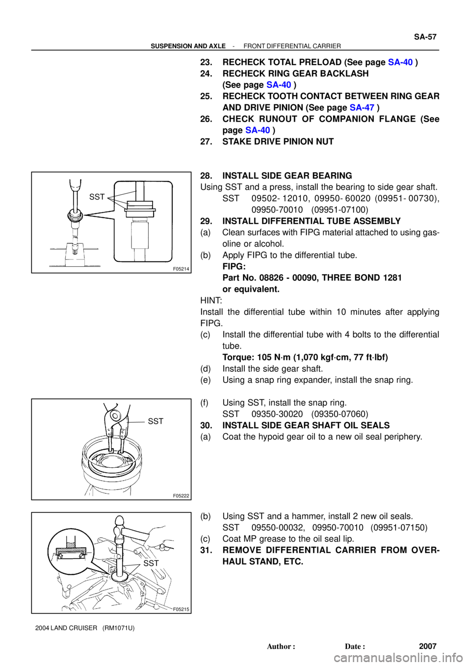
28. INSTALL SIDE GEAR BEARING
Using SST and a press, install the bearing to side gear shaft.
SST 09502- 12010, 09950- 60020 (09951- 00730),
09950-70010 (09951-07100)
29. INSTALL DIFFERENTIAL TUBE ASSEMBLY
(a) Clean surfaces with FIPG material attached to using gas-
oline or alcohol.
(b) Apply FIPG to the differential tube.
FIPG:
Part No. 08826 - 00090, THREE BOND 1281
or equivalent.
HINT:
Install the differential tube within 10 minutes after applying
FIPG.
(c) Install the differential tube with 4 bolts to the differential
tube.
Torque: 105 N´m (1,070 kgf´cm, 77 ft´lbf)
(d) Install the side gear shaft.
(e) Using a snap ring expander, install the snap ring.
(f) Using SST, install the snap ring.
SST 09350-30020 (09350-07060)
30. INSTALL SIDE GEAR SHAFT OIL SEALS
(a) Coat the hypoid gear oil to a new oil seal periphery.
(b) Using SST and a hammer, install 2 new oil seals.
SST 09550-00032, 09950-70010 (09951-07150)
(c) Coat MP grease to the oil seal lip.
31. REMOVE DIFFERENTIAL CARRIER FROM OVER-
HAUL STAND, ETC.