Page 2958 of 3115

REMOVAL
1. REMOVE FRONT WHEEL
Torque: 131 N´m (1,")
SA150-02
F04377
F04378
SST
F04379
Matchmarks
SA-70
- SUSPENSION AND AXLEFRONT UPPER SUSPENSION ARM
2020 Author�: Date�:
2004 LAND CRUISER (RM1071U)
REMOVAL
1. REMOVE FRONT WHEEL
Torque: 131 N´m (1,340 kgf´cm, 97 ft´lbf)
2. REMOVE FRONT FENDER APRON
3. DISCONNECT ABS SPEED SENSOR WIRE HARNESS
Remove the 2 bolts and disconnect the ABS speed sensor wire
harness.
Torque: 13 N´m (130 kgf´cm, 10 ft´lbf)
4. DISCONNECT STEERING KNUCKLE FROM UPPER
SUSPENSION ARM
(a) Support the lower suspension arm with a jack.
(b) Remove the cotter pin and nut.
Torque: 110 N´m (1,125 kgf´cm, 81 ft´lbf)
HINT:
At the time of installation, if the holes for the cotter pin are not
aligned, tighten the nut further up to 60°.
(c) Using SST, disconnect the steering knuckle from the up-
per suspension arm.
SST 09628-6201 1
5. REMOVE UPPER SUSPENSION ARM
(a) Place matchmarks on the front and rear No. 2 adjust cams
and body.
(b) Remove the 2 nuts, No. 1 and No. 2 camber adjust cams
and upper suspension arm.
Torque: 98 N´m (1,000 kgf´cm, 72 ft´lbf)
HINT:
At the time of installation, after stabilizing the suspension,
torque the nuts.
Page 2960 of 3115

FRONT WHEEL ALIGNMENT
INSPECTION
1. MEASURE VEHICLE HEIGHT")
F05219
Front:
Rear:A
B
C
DSA142-03
Z03382
SA-6
- SUSPENSION AND AXLEFRONT WHEEL ALIGNMENT
1956 Author�: Date�:
2004 LAND CRUISER (RM1071U)
FRONT WHEEL ALIGNMENT
INSPECTION
1. MEASURE VEHICLE HEIGHT
Vehicle height:
FrontA - B: 71 mm (2.795 in.)
RearC - D: 51 mm (2.008 in.)
Measuring points:
A: Ground clearance of spindle center
B: Ground clearance of lower suspension arm front bolt center
C: Ground clearance of rear axle shaft center
D: Ground clearance of lower control arm front bolt center
NOTICE:
Before inspecting the wheel alignment, adjust the vehicle
height to the specified value.
If the vehicle height is not the specified value, try to adjust it by
pushing down on or lifting the body.
2. INSTALL CAMBER-CASTER-KINGPIN GAUGE OR
POSITION VEHICLE ON WHEEL ALIGNMENT TES-
TER
Follow the specific instructions of the equipment manufacturer.
3. INSPECT CAMBER, CASTER AND STEERING AXIS
INCLINATION
Camber, caster and steering axis inclination:
Camber
Right-left error0°05' ± 45' (0.08° ± 0.75°)
30' (0.5°) or less
Caster
Right-left error2°30' ± 45' (2.5° ± 0.75°)
30' (0.5°) or less
Steering axis inclination
Right-left error12°10' ± 45' (12.17° ± 0.75°)
30' (0.5°) or less
If the steering axis inclination is not within the specified value,
after the camber and caster have been correctly adjusted, re-
check the steering knuckle and front wheel for bearing or loose-
ness.
Page 2964 of 3115
SA0028
AB
FrontBA
A: Inside
B: Outside
F05200
SA-10
- SUSPENSION AND AXLEFRONT WHEEL ALIGNMENT
1960 Author�: Date�:
2004 LAND CRUISER (RM1071U)
7. INSPECT AND ADJUST WHEEL ANGLE
(a) Turn the steering wheel fully, and measure the turning
angle.
Wheel turning angle:
Inside wheel36°42' (33°42' - 36°42')
36.7° (33.7° - 36.7°)
Outside wheel: Reference32°36'
32.6°
If the right and left inside wheel angles differ from the specified
value, check the right and left rack end lengths.
(b) When toe-in is normal after inspection, adjust wheel
angle with the knuckle stopper bolt of the lower suspen-
sion arm.
Torque: 44 N´m (450 kgf´cm, 32 ft´lbf)
Page 3054 of 3115
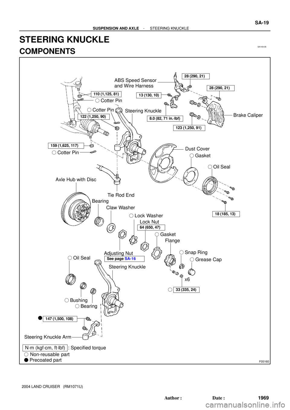
SA149-05
F05160
� Cotter Pin
� Cotter Pin
159 (1,625, 117)
� Cotter Pin
Axle Hub with Disc
Tie Rod End
ABS Speed Sensor
and Wire Harness28 (290, 21)
13 (130, 10)
Brake Caliper
Dust Cover
� Gasket
� Oil Seal
18 (185, 13)
Bearing
Claw Washer
Adjusting Nut
Lock Nut � Lock Washer
� Gasket
Flange
� Snap Ring
� Grease Cap
33 (335, 24)
x6
Steering Knuckle
� Oil Seal
� Bushing
� Bearing
147 (1,500, 108)�
Steering Knuckle Arm
N´m (kgf´cm, ft´lbf) : Specified torque
� Non-reusable part
� Precoated part
Steering Knuckle
8.0 (82, 71 in.´lbf)
123 (1,250, 91)
122 (1,250, 90)
28 (290, 21)
�
64 (650, 47)
See page SA-16
110 (1,125, 81)
- SUSPENSION AND AXLESTEERING KNUCKLE
SA-19
1969 Author�: Date�:
2004 LAND CRUISER (RM1071U)
STEERING KNUCKLE
COMPONENTS
Page 3055 of 3115
SA14B-04
F04346
SA-22
- SUSPENSION AND AXLESTEERING KNUCKLE
1972 Author�: Date�:
2004 LAND CRUISER (RM1071U)
DISASSEMBLY
1. REMOVE STEERING KNUCKLE ARM
Remove the 2 bolts and steering knuckle arm.
2. REMOVE OIL SEAL
Using a screwdriver and hammer, remove the oil seal.
3. REMOVE BEARING AND BUSHING
Using a brass and hammer, remove the bearing and bushing.
Page 3056 of 3115

INSTALLATION
1. INSTALL STEERING KNUCKLE
(a) Apply synthetic oil and lithium")
SA14D-04
F04405
F04372
A
BC SA-24
- SUSPENSION AND AXLESTEERING KNUCKLE
1974 Author�: Date�:
2004 LAND CRUISER (RM1071U)
INSTALLATION
1. INSTALL STEERING KNUCKLE
(a) Apply synthetic oil and lithium soap base chassis grease,
NLGI No. 1 to the drive shaft.
(b) Support the lower suspension arm with jack and connect
the steering knuckle to the lower suspension arm.
NOTICE:
Be careful not to damage the oil seal.
(c) Temporarily install the nut to lower suspension arm.
(d) Raise up the lower suspension arm using a jack and
install the steering knuckle to the upper suspension arm
with a nut.
Torque: 110 N´m (1,125 kgf´cm, 81 ft´lbf)
(e) Install a new cotter pin.
If the holes for the cotter pin are not aligned, tighten the nut fur-
ther up to 60°.
(f) Torque the nut of the lower suspension arm.
Torque: 159 N´m (1,625 kgf´cm, 117 ft´lbf)
(g) Install a new cotter pin.
2. CONNECT TIE ROD END
(a) Connect the tie rod end to steering knuckle with nut.
Torque: 122 N´m (1,250 kgf´cm, 91 ft´lbf)
(b) Install a new cotter pin.
If the holes for the cotter pin are not aligned, tighten the nut fur-
ther up to 60°.
3. CONNECT ABS SPEED SENSOR AND WIRE HAR-
NESS
Install the wire harness and 3 bolts.
Torque:
A: 8.0 N´m (82 kgf´cm, 71 in.´lbf)
B: 13 N´m (130 kgf´cm, 10 ft´lbf)
C: 28 N´m (290 kgf´cm, 21 ft´lbf)
4. INSTALL DUST COVER, GASKET AND OIL SEAL
Install the dust cover, new gasket and oil seal with the 4 bolts.
Torque: 18 N´m (185 kgf´cm, 13 ft´lbf)
5. INSTALL FRONT AXLE HUB (See page SA-16)
Page 3057 of 3115
SA14C-04
F04348
SST
F04349
SST
- SUSPENSION AND AXLESTEERING KNUCKLE
SA-23
1973 Author�: Date�:
2004 LAND CRUISER (RM1071U)
REASSEMBLY
1. INSTALL BEARING AND BUSHING
(a) Using SST and a press, install a new bearing and bush-
ing.
SST 09950-60010 (09951-00540),
09950-70010 (09951-07100)
(b) Apply synthetic oil and lithium soap base chassis grease,
NLGI No. 1 to the steering knuckle inner side of the bush-
ing.
2. INSTALL OIL SEAL
(a) Using SST and a press, install a new oil seal.
SST 09950-60020 (09951-00910),
09950-70010 (09951-07100)
(b) Coat the lip of the oil seal with MP grease.
3. INSTALL STEERING KNUCKLE ARM
(a) Clean the threads of the 2 bolts and steering knuckle with
toluene or trichloroethylene.
(b) Apply sealant to the bolt threads.
Sealant:
Part No. 08833-00070, THREE BOND 1324
or equivalent
(c) Install the steering knuckle arm with the 2 bolts.
Torque: 147 N´m (1,500 kgf´cm, 108 ft´lbf)
Page 3058 of 3115
SA14A-04
F04371
F04372
F04373
SST
F04374
SST
SA-20
- SUSPENSION AND AXLESTEERING KNUCKLE
1970 Author�: Date�:
2004 LAND CRUISER (RM1071U)
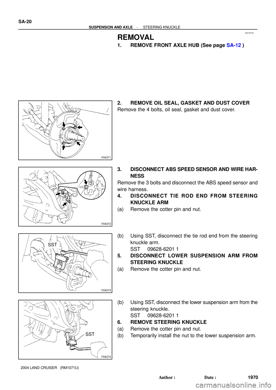
REMOVAL
1. REMOVE FRONT AXLE HUB (See page SA-12)
2. REMOVE OIL SEAL, GASKET AND DUST COVER
Remove the 4 bolts, oil seal, gasket and dust cover.
3. DISCONNECT ABS SPEED SENSOR AND WIRE HAR-
NESS
Remove the 3 bolts and disconnect the ABS speed sensor and
wire harness.
4. DISCONNECT TIE ROD END FROM STEERING
KNUCKLE ARM
(a) Remove the cotter pin and nut.
(b) Using SST, disconnect the tie rod end from the steering
knuckle arm.
SST 09628-6201 1
5. DISCONNECT LOWER SUSPENSION ARM FROM
STEERING KNUCKLE
(a) Remove the cotter pin and nut.
(b) Using SST, disconnect the lower suspension arm from the
steering knuckle.
SST 09628-6201 1
6. REMOVE STEERING KNUCKLE
(a) Remove the cotter pin and nut.
(b) Temporarily install the nut to the lower suspension arm.