Page 172 of 3115

I25241
ºTUNE DOWNº Switch
ºTUNE UPº Switch
BE-136
- BODY ELECTRICALAUDIO SYSTEM
2509 Author�: Date�:
2004 LAND CRUISER (RM1071U)
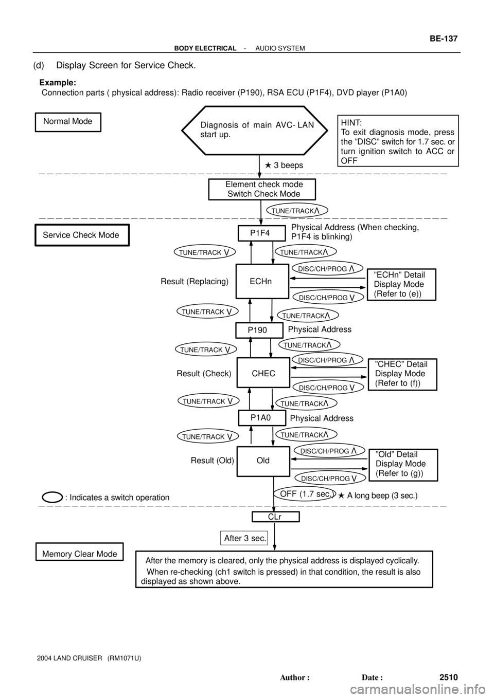
(c) Service check mode
(1) After the element check and switch check is completed, the system enters service check mode
when ºTUNE UPº switch is pressed.
(2) Error codes over the tuner and connected equipments are displayed on the screen of the tuner.
Results for each check are displayed as follows:
�good:
No DTC is detected for both ºSystem Check Confirmationº and ºDiagnosis Memory Re-
sponseº.
�nCon:
The component does not respond to the ºDiagnosis On Instructionº command.
Applicable to only the system where connected components are limited to be used.
�ECHn:
Application of new version has been confirmed by the ºDiagnosis On Checkº, and there
is one or more DTC which indicates ºReplacementº in the ºSystem Check Result Re-
sponseº or ºDiagnosis Memory Responseº.
�CHEC:
Application of new version has been confirmed by the ºDiagnosis On Checkº, and there
is no DTC which indicates ºReplacementº in the ºSystem Check Result Responseº or
ºDiagnosis Memory Responseº, but one or more DTC which indicates ºCheckº is identified.
�Old:
Application of old version is confirmed by the ºDiagnosis On Checkº, and DTC is identified
in the ºSystem Check Result Responseº or ºDiagnosis Memory Responseº.
�nrES:
No response is identified to the ºSystem Check Start Instructionº and ºRequest for System
Check Resultº commands.
HINT:
�Check the present and past condition of components by performing the System Check and collecting
stored DTC memories.
�Check results are displayed as one of the following six indications: ºgoodº, ºECHnº, ºCHECº,ºnConº,
ºOldº or ºnrESº.
Page 173 of 3115

Normal Mode
Service Check ModePhysical Address (When checking,
P1F4 is blinking)
� A long beep (3 sec.) � 3 beeps
Memory Clear ModeAfter 3 sec.
P1F4
ECHn
CLr Example:
Connection parts ( physical address): Radio receiver (P190), RSA ECU (P1F4), DVD player (P1A0)
Diagnosis of main AVC- LAN
start up.
HINT:
To exit diagnosis mode, press
the ºDISCº switch for 1.7 sec. or
turn ignition switch to ACC or
OFF
ºECHnº Detail
Display Mode
(Refer to (e))
CHEC
ºCHECº Detail
Display Mode
(Refer to (f))
Physical AddressP190
Physical AddressP1A0
Old
ºOldº Detail
Display Mode
(Refer to (g))
Result (Replacing)
Result (Check)
Result (Old)
� After the memory is cleared, only the physical address is displayed cyclically.OFF (1.7 sec.)
: Indicates a switch operation
� When re-checking (ch1 switch is pressed) in that condition, the result is also
displayed as shown above.
Element check mode
Switch Check Mode
VTUNE/TRACK
VTUNE/TRACK
VTUNE/TRACK
VTUNE/TRACK
VTUNE/TRACK
VTUNE/TRACK
VTUNE/TRACK
VTUNE/TRACK
VTUNE/TRACK
VTUNE/TRACK
VTUNE/TRACK
VDISC/CH/PROG
VDISC/CH/PROG
VDISC/CH/PROG
VDISC/CH/PROG
VDISC/CH/PROG
VDISC/CH/PROG
- BODY ELECTRICALAUDIO SYSTEM
BE-137
2510 Author�: Date�:
2004 LAND CRUISER (RM1071U)
(d) Display Screen for Service Check.
Page 174 of 3115

Service Check Mode
ºECHnº Detail Display Mode
Physical Address of Component
Logical Address
Number of Occurrence (*2)
DTC (Refer to diagnostic
trouble code chart)
Logical Address
Connection Check Code (*2)
Continued if more than one DTC is identified.Details for 1st
Component
Details for 2nd
Component ECHn
P1F4
P1F4
SyS
COdE
DTC (Refer to diagnostic
trouble code chart)
Auxiliary Code (*1)
OFF (Along)
CLr
: Indicates a switch operation
Detail code is displayed
cyclically.
(*1): Some diagnostic codes
may not be displayed. In this
case, º- - -º displayed.
(*2): Some diagnostic codes
may not be displayed. In this
case, º- -º displayed.1L
**
1d21
2L**
2dD7
2P***
2n**
2c**
VTUNE/TRACK VTUNE/TRACK
VDISC/CH/PROG VDISC/CH/PROG
VTUNE/TRACK
VTUNE/TRACK
VTUNE/TRACK
VTUNE/TRACK
VTUNE/TRACK
VTUNE/TRACK
VTUNE/TRACK
VTUNE/TRACK
VTUNE/TRACK
VTUNE/TRACK
VTUNE/TRACK
VTUNE/TRACK
VTUNE/TRACK
VTUNE/TRACK
VTUNE/TRACK
VTUNE/TRACK
VTUNE/TRACK
VTUNE/TRACK
VTUNE/TRACK
VTUNE/TRACK
VTUNE/TRACK
VTUNE/TRACK
VTUNE/TRACK VTUNE/TRACK
BE-138
- BODY ELECTRICALAUDIO SYSTEM
2511 Author�: Date�:
2004 LAND CRUISER (RM1071U)
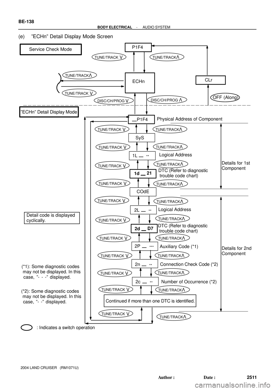
(e) ºECHnº Detail Display Mode Screen
Page 175 of 3115

Service Check Mode
ºCHECº Detail Display Mode
Physical Address of Component
Logical Address
Number of Occurrence (*2)
DTC (Refer to diagnostic
trouble code chart)
Continued if more than one DTC is identified.Details for 1st
Component
Details for 2nd
Component CHEC
P190
P190
COde
DTC (Refer to diagnostic
trouble code chart)
CLr
: Indicates a switch operationAuxiliary Code (*1)
Connection Check Code (*2)
Logical Address
Connection Check Code (*2)
Detail code is displayed
cyclically.
Auxiliary Code (*1)
Number of Occurrence (*2)
1L**
1dE4
2L**
2d43
2P***
2n**
1P***
1n**
2c**
1c**
(*1): Some diagnostic codes
may not be displayed. In this
case, º- - -º displayed.
(*2): Some diagnostic codes
may not be displayed. In this
case, º- -º displayed.
VTUNE/TRACK
VTUNE/TRACK
VDISC/CH/PROG VDISC/CH/PROG
VTUNE/TRACK
VTUNE/TRACK
VTUNE/TRACK
VTUNE/TRACK
VTUNE/TRACK
VTUNE/TRACK
VTUNE/TRACK
VTUNE/TRACK
VTUNE/TRACK
VTUNE/TRACK
VTUNE/TRACK
VTUNE/TRACK
VTUNE/TRACK
VTUNE/TRACK
VTUNE/TRACK
VTUNE/TRACK
VTUNE/TRACK
VTUNE/TRACK
VTUNE/TRACK
VTUNE/TRACK
VTUNE/TRACK VTUNE/TRACK
VTUNE/TRACK
VTUNE/TRACK
VTUNE/TRACK
VTUNE/TRACK
VTUNE/TRACK
VTUNE/TRACK
OFF (Along)
- BODY ELECTRICALAUDIO SYSTEM
BE-139
2512 Author�: Date�:
2004 LAND CRUISER (RM1071U)
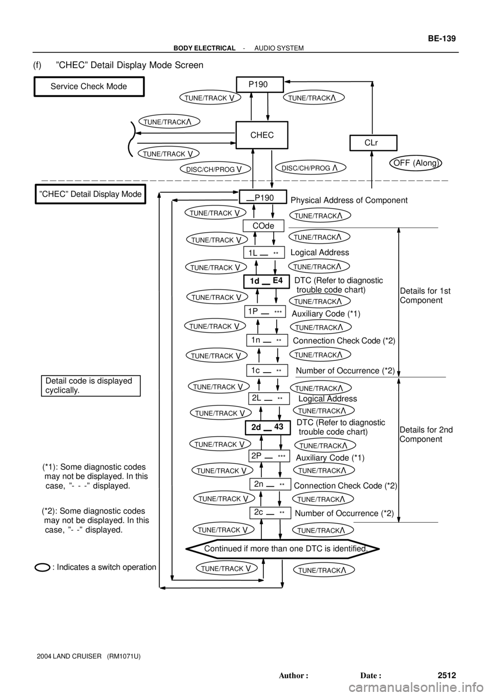
(f) ºCHECº Detail Display Mode Screen
Page 176 of 3115

Service Check Mode
ºOldº Detail Display Mode
Physical Address of Component
Logical Address
Number of Occurrence (*2)
DTC (Refer to diagnostic
trouble code chart)
Continued if more than one DTC is identified.Details for 1st
Component
Details for 2nd
Component Old
P1A0
P1A0
COdE
DTC (Refer to diagnostic
trouble code chart)
CLr
: Indicates a switch operationAuxiliary Code (*1)
Connection Check Code (*2)
Logical Address
Connection Check Code (*2)
Detail code is displayed
cyclically.
Auxiliary Code (*1)
Number of Occurrence (*2)
1L**
1dd4
2L**
2d43
2P***
2n**
1P***
1n**
2c
1c- -
- - (*1): Some diagnostic codes
may not be displayed. In this
case, º- - -º displayed.
(*2): Some diagnostic codes
may not be displayed. In this
case, º- -º displayed.
VTUNE/TRACK
VTUNE/TRACK
VTUNE/TRACK
VTUNE/TRACK
VTUNE/TRACK
VTUNE/TRACK
VTUNE/TRACK
VTUNE/TRACK
VTUNE/TRACK
VTUNE/TRACK
VTUNE/TRACK
VTUNE/TRACK
VTUNE/TRACK
VTUNE/TRACK
VTUNE/TRACK
VTUNE/TRACK
VTUNE/TRACK
VTUNE/TRACK
VTUNE/TRACK
VTUNE/TRACK
VTUNE/TRACK
VTUNE/TRACK
VTUNE/TRACK
VTUNE/TRACK
OFF (Along) VDISC/CH/PROG VDISC/CH/PROG
VTUNE/TRACK
VTUNE/TRACK
VTUNE/TRACK VTUNE/TRACK
VTUNE/TRACK VTUNE/TRACK
BE-140
- BODY ELECTRICALAUDIO SYSTEM
2513 Author�: Date�:
2004 LAND CRUISER (RM1071U)
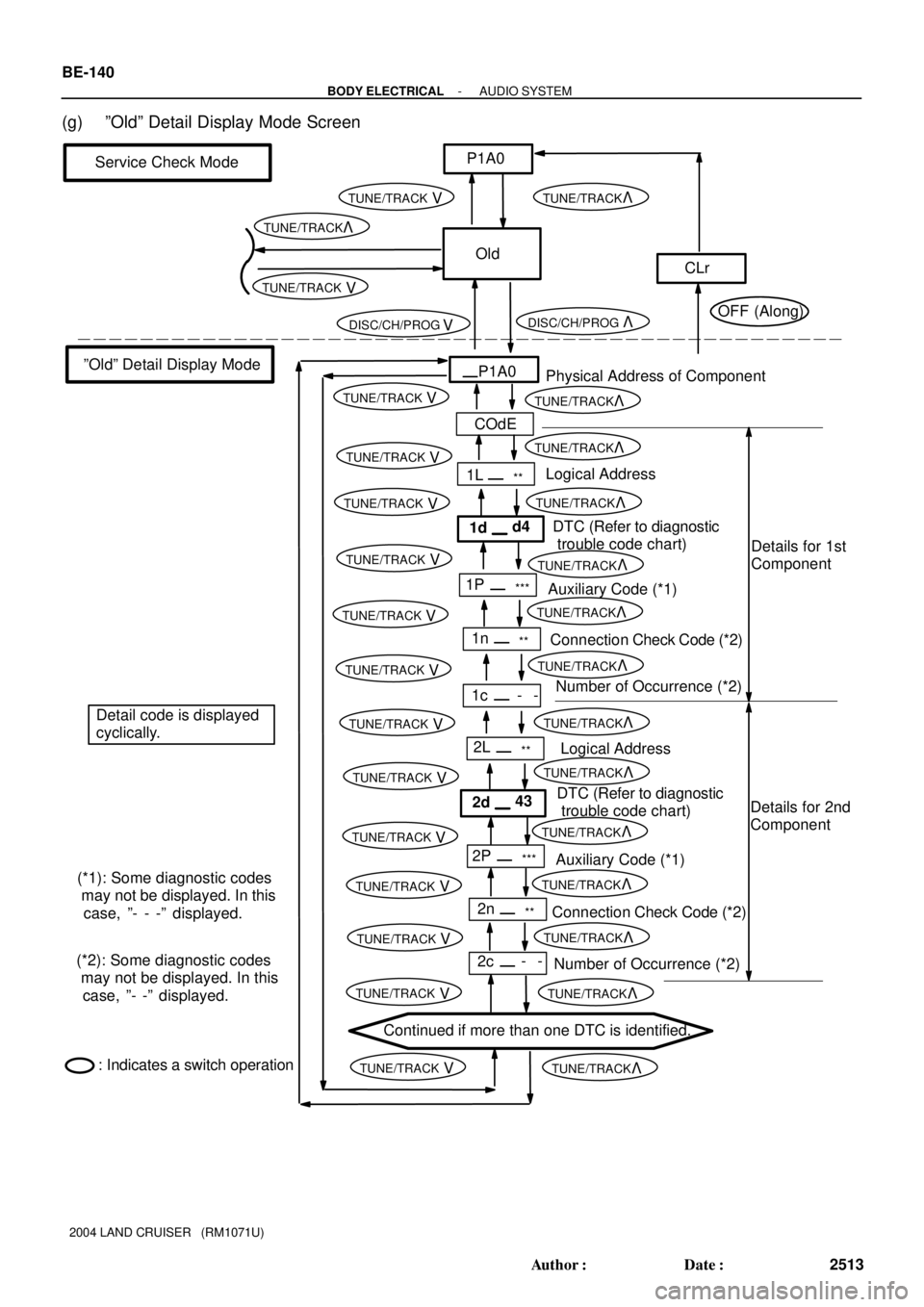
(g) ºOldº Detail Display Mode Screen
Page 206 of 3115

BE01I-05
- BODY ELECTRICALBODY ELECTRICAL SYSTEM
BE-1
2374 Author�: Date�:
2004 LAND CRUISER (RM1071U)
BODY ELECTRICAL SYSTEM
PRECAUTION
HINT:
Take care to observe the following precautions when performing inspections or removal and replacement
of body electrical related parts.
1. HEADLIGHT SYSTEM
Halogen bulbs have pressurized gas inside and require special handling. They can burst if scratched or
dropped. Hold a bulb only by its plastic or metal case. Don't touch the glass part of a bulb with bare hands.
2. SRS (SUPPLEMENTAL RESTRAINT SYSTEM)
The LAND CRUISER is equipped with an SRS (Supplemental Restraint System) such as the driver airbag
and front passenger airbag. Failure to carry out service operation in the correct sequence could cause the
SRS to unexpectedly deploy during servicing, possibly leading to a serious accident. Before servicing (in-
cluding removal or installation of parts, inspection or replacement), be sure to read the precautionary notices
in the RS section.
3. AUDIO SYSTEM
�If the negative (-) terminal cable is disconnected from the battery, the preset AM, FM 1 and FM 2 sta-
tions stored in memory are erased, so be sure to note the stations and reset them after the negative
(-) terminal cable is reconnected to the battery.
�If the negative (-) terminal cable is disconnected from the battery, the ºANTI-THEFT SYSTEMº will
operate when the cable is reconnected, but the radio, tape player and CD player will not operate. Be
sure to input the correct ID number so that the radio, tape player and CD player can be operated again.
4. MOBILE COMMUNICATION SYSTEM
If the vehicle is equipped with a mobile communication system, refer to precautions in the IN section.
Page 381 of 3115
BO1JA-04
H20972
Door Glass Run Door Glass
Outside Handle
Door Lock Cylinder
Door Lock
Window RegulatorLower FrameDoor Belt Moulding
Tweeter Speaker
Lower Frame
Bracket Garnish Outside Rear View Mirror
Service
Hole Cover Door Inside
Handle Bezel
No. 1Inside Handle
Door Courtesy Light
Door TrimSpeaker
Door Hinge Door Check
5.0 (51, 44 in.´lbf)
5.0 (51, 44 in.´lbf)
26 (265, 19)
26 (265, 19)
�
: Specified torqueN´m (kgf´cm, ft´lbf)
� Precoated part
8.0 (82, 71 in.´lbf)
27 (275, 20)
5.0 (51, 44 in.´lbf)
Power Window Switch
Door Lock Link
Protector
8.0 (82, 71 in.´lbf)
8.0 (82, 71 in.´lbf)Door Inside
Handle Bezel No. 2
Door Check Cover
8.0 (82, 71 in.´lbf)
8.0 (82, 71 in.´lbf)
5.0 (51, 44 in.´lbf)
23 (235, 17)
23 (235, 17)
BO-8
- BODYFRONT DOOR
2582 Author�: Date�:
2004 LAND CRUISER (RM1071U)
FRONT DOOR
COMPONENTS
Page 383 of 3115

H04821
: Clip
H21409
H04754
H04755
BO-10
- BODYFRONT DOOR
2584 Author�: Date�:
2004 LAND CRUISER (RM1071U)
6. REMOVE DOOR TRIM
(a) Remove the 2 caps and the 7 screws.
(b) Remove the 3 clips.
(c) Insert a screwdriver between the door and the door trim
to pry the trim.
NOTICE:
Be careful not to damage the door and the door trim.
HINT:
Tape up the screwdriver tip before use.
(d) Pull the trim upward to remove it.
7. REMOVE INSIDE HANDLE
(a) Remove the screw and the inside handle.
(b) Disconnect the 2 control cables from the inside handle as
shown in the illustration.
8. REMOVE TWEETER SPEAKER
Disconnect the connector, then remove the bolt and the tweeter
speaker.
9. REMOVE OUTSIDE REAR VIEW MIRROR
Disconnect the connector, then remove the 3 bolts and the out-
side rear view mirror.
10. REMOVE SERVICE HOLE COVER
(a) Remove the clamps and the wire harness.
(b) Remove the service hole cover.
NOTICE:
Do not tear the cover.
HINT:
At the time of reassembly, pull out the 2 control cables and wire
harness through the service hole cover.
11. REMOVE DOOR BELT MOULDING
(a) Remove the screw.
(b) Using a scraper, remove the door belt moulding.
HINT:
Tape up the scraper tip before use.
12. REMOVE DOOR GLASS
(a) Open the door glass until the bolts appear in the service
hole.
(b) Remove the 2 bolts and the door glass.
Torque: 8.0 N´m (82 kgf´cm, 71 in.´lbf)
NOTICE:
Do not damage the door glass.
HINT:
Pull the glass upward to remove it.
13. REMOVE SPEAKER
Remove the 3 screws and the speaker, then disconnect the
connector.
14. REMOVE DOOR GLASS RUN
15. REMOVE LOWER FRAME
Remove the bolt and the lower frame.