Page 1881 of 3115
A07245
A05084
A05119
A04857
EM-80
- ENGINE MECHANICALENGINE UNIT
1653 Author�: Date�:
2004 LAND CRUISER (RM1071U)
22. REMOVE TORQUE CONVERTER CLUTCH BOLTS
(a) Remove the bolt and the flywheel housing under cover.
(b) Turn the crankshaft pulley bolt to gain access to each bolt.
(c) Hold the crankshaft pulley bolt with a wrench, and remove
the 6 bolts.
23. REMOVE TRANSMISSION
(a) Remove the 10 bolts.
(b) Remove the transmission together with the torque con-
verter clutch from the engine.
24. REMOVE DRIVE PLATE
Hold the crankshaft pulley bolt with a wrench, and remove the
8 bolts, the front spacer, the drive plate and the rear spacer.
Page 2473 of 3115

B06412
B06415
Drain Plug
B06413Drain Plug
- MAINTENANCECHASSIS
MA-9
57 Author�: Date�:
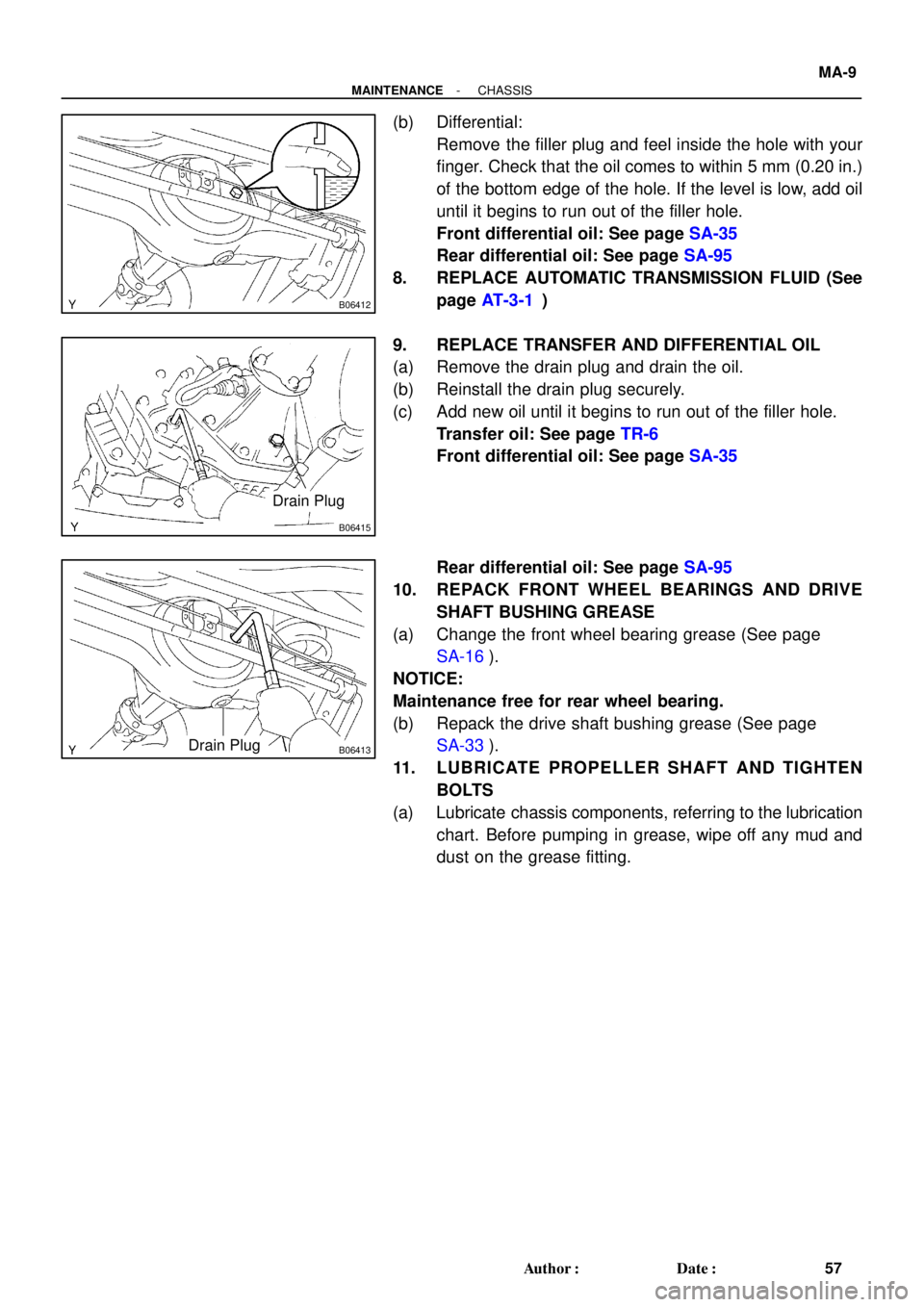
(b) Differential:
Remove the filler plug and feel inside the hole with your
finger. Check that the oil comes to within 5 mm (0.20 in.)
of the bottom edge of the hole. If the level is low, add oil
until it begins to run out of the filler hole.
Front differential oil: See page SA-35
Rear differential oil: See page SA-95
8. REPLACE AUTOMATIC TRANSMISSION FLUID (See
page AT-3-1)
9. REPLACE TRANSFER AND DIFFERENTIAL OIL
(a) Remove the drain plug and drain the oil.
(b) Reinstall the drain plug securely.
(c) Add new oil until it begins to run out of the filler hole.
Transfer oil: See page TR-6
Front differential oil: See page SA-35
Rear differential oil: See page SA-95
10. REPACK FRONT WHEEL BEARINGS AND DRIVE
SHAFT BUSHING GREASE
(a) Change the front wheel bearing grease (See page
SA-16).
NOTICE:
Maintenance free for rear wheel bearing.
(b) Repack the drive shaft bushing grease (See page
SA-33).
11. LUBRICATE PROPELLER SHAFT AND TIGHTEN
BOLTS
(a) Lubricate chassis components, referring to the lubrication
chart. Before pumping in grease, wipe off any mud and
dust on the grease fitting.
Page 2782 of 3115

AB0163
Wire Harness
Diameter
Stripped Wire Harness Section
H20646
L
M
H20057
SST
- SUPPLEMENTAL RESTRAINT SYSTEMSTEERING WHEEL PAD AND SPIRAL CABLE
RS-23
2298 Author�: Date�:
2004 LAND CRUISER (RM1071U)
HINT:
Have a battery ready as the power source to deploy the airbag.
(a) Remove the steering wheel pad (See page SR-14).
CAUTION:
�When storing the steering wheel pad, keep the upper
surface of the pad facing upward.
�When removing the steering wheel pad, work must be
started 90 seconds after the ignition switch is turned
to the ºLOCKº position and the negative (-) terminal
cable is disconnected from the battery.
(b) Using a service-purpose wire harness for the vehicle, tie
down the steering wheel pad to the disc wheel.
Wire harness: Stripped wire harness section
1.25 mm
2
or more (0.0019 in2. or more).
CAUTION:
If a wire harness which is too thin or some other thing is
used to tie down the steering wheel pad, it may be snapped
by the shock when the airbag is deployed. This is highly
dangerous. Always use a wire harness for vehicle use
which is at least 1.25 mm
2
(0.0019 in2).
HINT:
To calculate the square of the stripped wire harness section:
Square = 3.14 x (Diameter)
2
divided by 4
(1) Install the 2 bolts with washers in the 2 bolt holes in
the steering wheel pad.
Bolt:
L: 35.0 mm (1.387 in.)
M: 6.0 mm (0.236 in.)
Pitch: 1.0 mm (0.039 in.)
NOTICE:
�Tighten the bolts by hand until the bolts become diffi-
cult to turn.
�Do not tighten the bolts excessively.
(2) Connect the connectors of the SST to the steering
wheel pad connectors.
SST 09082-00802 (09082-10801, 09082-30801)
Page 2783 of 3115

H20060
2 Times or more
H20058
AB0158
SSTBattery RS-24
- SUPPLEMENTAL RESTRAINT SYSTEMSTEERING WHEEL PAD AND SPIRAL CABLE
2299 Author�: Date�:
2004 LAND CRUISER (RM1071U)
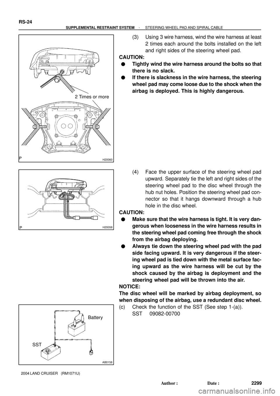
(3) Using 3 wire harness, wind the wire harness at least
2 times each around the bolts installed on the left
and right sides of the steering wheel pad.
CAUTION:
�Tightly wind the wire harness around the bolts so that
there is no slack.
�If there is slackness in the wire harness, the steering
wheel pad may come loose due to the shock when the
airbag is deployed. This is highly dangerous.
(4) Face the upper surface of the steering wheel pad
upward. Separately tie the left and right sides of the
steering wheel pad to the disc wheel through the
hub nut holes. Position the steering wheel pad con-
nector so that it hangs downward through a hub
hole in the disc wheel.
CAUTION:
�Make sure that the wire harness is tight. It is very dan-
gerous when looseness in the wire harness results in
the steering wheel pad coming free through the shock
from the airbag deploying.
�Always tie down the steering wheel pad with the pad
side facing upward. It is very dangerous if the steer-
ing wheel pad is tied down with the metal surface fac-
ing upward as the wire harness will be cut by the
shock caused by the airbag is deployment and the
steering wheel pad will be thrown into the air.
NOTICE:
The disc wheel will be marked by airbag deployment, so
when disposing of the airbag, use a redundant disc wheel.
(c) Check the function of the SST (See step 1-(a)).
SST 09082-00700
Page 2828 of 3115
SR-66
- STEERINGPOWER STEERING GEAR
2275 Author�: Date�:
2004 LAND CRUISER (RM1071U)
10. INSTALL NO. 1 ENGINE UNDER COVER
Tighten the 7 bolts.
11. POSITION FRONT WHEELS FACING STRAIGHT
AHEAD
HINT:
Do it with the front of the vehicle jacked up.
12. CENTER SPIRAL CABLE (See page SR-24)
13. INSTALL STEERING WHEEL
(a) Align the matchmarks on the wheel and steering column
main shaft.
(b) Temporarily tighten the wheel set nut.
(c) Connect the connector.
14. BLEED POWER STEERING SYSTEM (See page
SR-4)
15. CHECK STEERING WHEEL CENTER POINT
16. TORQUE STEERING WHEEL SET NUT
Torque: 50 N´m (510 kgf´cm, 37 ft´lbf)
17. INSTALL STEERING WHEEL PAD (See page SR-24)
18. CHECK FRONT WHEEL ALIGNMENT (See page
SA-6)
19. PERFORM ZERO POINT CALIBRATION OF YAW RATE
AND DECELERATION SENSORS (See page DI-505)
Page 2834 of 3115

SR0MK-08
F12852
SST
R13479
Matchmarks
- STEERINGPOWER STEERING GEAR
SR-51
2260 Author�: Date�:
2004 LAND CRUISER (RM1071U)
REMOVAL
NOTICE:
Remove the steering wheel assembly before the steering
gear removal, because there is possibility of breaking of
the spiral cable.
1. PLACE FRONT WHEELS FACING STRAIGHT AHEAD
2. REMOVE STEERING WHEEL PAD
(See page SR-14)
3. REMOVE STEERING WHEEL (See page SR-14)
4. REMOVE NO. 1 ENGINE UNDER COVER
Remove the 7 bolts.
5. REMOVE NO. 2 ENGINE UNDER COVER
Remove the 6 bolts.
6. DISCONNECT RH AND LH TIE ROD ENDS
(See page SA-20)
7. REMOVE ENGINE OIL FILTER ASSEMBLY
(a) Disconnect the 2 clips and hoses.
(b) Remove the 2 bolts and nut with the bracket.
(c) Remove the O-ring.
8. DISCONNECT NO. 2 INTERMEDIATE SHAFT AS-
SEMBLY (See page SR-14)
HINT:
Turn the steering wheel fully to the right side.
9. DISCONNECT PRESSURE FEED TUBE
Remove the union bolt, gasket and disconnect the pressure
feed tube.
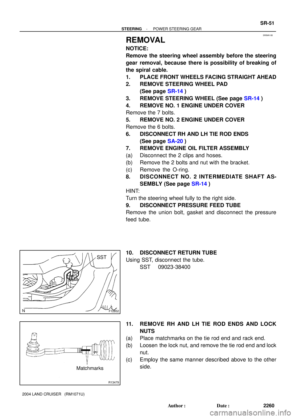
10. DISCONNECT RETURN TUBE
Using SST, disconnect the tube.
SST 09023-38400
11. REMOVE RH AND LH TIE ROD ENDS AND LOCK
NUTS
(a) Place matchmarks on the tie rod end and rack end.
(b) Loosen the lock nut, and remove the tie rod end and lock
nut.
(c) Employ the same manner described above to the other
side.
Page 2884 of 3115

SA16A-02
F04391
F04392
F04393
F04394
SA-172
- SUSPENSION AND AXLECOIL SPRING AND REAR SHOCK ABSORBER
2122 Author�: Date�:
2004 LAND CRUISER (RM1071U)
REMOVAL
1. REMOVE REAR WHEELS
Torque: 131 N´m (1,340 kgf´cm, 97 ft´lbf)
2. SUPPORT REAR AXLE HOUSING WITH JACK
3. REMOVE SHOCK ABSORBER
(a) Remove the bolt and disconnect the shock absorber from
the axle housing.
Torque: 98 N´m (1,000 kgf´cm, 72 ft´lbf)
(b) Employ the same manner described above to the other
side.
(c) While holding the piston rod, remove the nut, 2 retainers,
cushion and shock absorber.
Torque: 69 N´m (704 kgf´cm, 51 ft´lbf)
(d) Remove the 2 retainers and cushion from the shock ab-
sorber.
4. DISCONNECT LH AND RH STABILIZER BAR BRACK-
ETS
Remove the 4 bolts and disconnect the LH and RH stabilizer bar
brackets.
Torque: 18 N´m (185 kgf´cm, 13 ft´lbf)
5. DISCONNECT LATERAL CONTROL ROD
Remove the nut, washer, bolt and disconnect the lateral control
rod.
Torque: 150 N´m (1,530 kgf´cm, 111 ft´lbf)
HINT:
At the time of installation, after stabilizing the suspension,
torque the nut and bolt.
6. DISCONNECT BREATHER HOSE
Page 2894 of 3115

SA167-05
F05181
F05083
F04360
SA-168
- SUSPENSION AND AXLEDIFFERENTIAL LOCKING SYSTEM
2118 Author�: Date�:
2004 LAND CRUISER (RM1071U)
REMOVAL
1. SHIFTING REAR DIFF. LOCK POSITION
(a) Turn the ignition switch to the ON position.
(b) Shift the transfer shift lever to L position.
(c) Turn the differential lock control switch to the RR position
and lock the rear differential.
HINT:
While rotating the rear wheels, check they are in the differential
lock condition.
(d) Disconnect the cable from the negative terminal of the
battery.
2. REMOVE NO. 1 ACTUATOR PROTECTOR
Remove the nut, bolt and No. 1 actuator protector.
3. REMOVE NO. 2 ACTUATOR PROTECTOR
Remove the 2 nuts and No. 2 actuator protector.
4. DISCONNECT CONNECTORS AND TUBE
5. REMOVE REAR DIFF. LOCK POSITION SWITCH
6. REMOVE COVER
(a) Remove the 3 bolts.
(b) Using a brass bar and hammer, remove the cover.
7. REMOVE ACTUATOR
(a) Remove the shift fork set bolt.
(b) Remove the 4 bolts.
(c) Using a screwdriver, pry out the actuator.