Page 65 of 73
AIR CONDITIONING
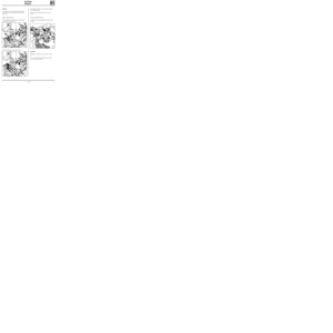
Condenser
62
13828R
REMOVAL
It is not necessary to use a lift.
Drain the R134a coolant circuit.
Disconnect the battery.
Remove:
- the plastic air deflector on the upper crossmem-
ber,
- the seal (1),
- the upper crossmember (2),
- the retaining bolt (3),
- the two R134a coolant pipes (4) (fit plugs to
prevent the entry of humidity),
- the two radiator upper retaining bolts.Move the radiator-condenser assembly as far back
as possible towards the engine.
Remove the four condenser to radiator retaining
bolts (6).
Carefully remove the condenser.
REFITTING
Proceed in the reverse order to removal.
Check the condition of the seals.
Create a vacuum, then fill the circuit with R134a
using the filling equipment.
IMPORTANT
When changing the condenser, add 30 ml of
P.A.G. SP 10 oil to the circuit.
NOTE: tightening torque of bolts (6) : 0.8 daN.m.
13830R
62-54
Page 66 of 73
AIR CONDITIONING
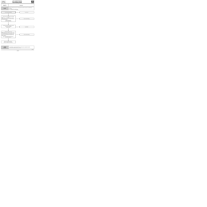
Pressure relief valve
62
13826R1
REPLACEMENT
Drain the R134a coolant circuit using the filling
equipment.
Remove:
- the connecting pipes retaining nut (A),
- the two pressure relief valve to evaporator re-
taining bolts (B).
On refitting, ensure that the pipe seals are in
good condition.
Bolt tightening torques:
- bolt (A) : 0.8 daN.m,
- bolt (B) : 0.6 daN.m.
Create a vacuum, then fill the R134a coolant cir-
cuit using the filling equipment.
62-55
Page 67 of 73
AIR CONDITIONING
Dehydration canister
62
13828R1
Remove the dehydration canister from under-
neath the vehicle.
Fit plugs on each hole to prevent any entry of hu-
midity into the components.
REFITTING
Proceed in the reverse order to removal.
Check that the seals are in good condition and lu-
bricate them with
P.A.G. SP 10 oil.
Create a vacuum, then fill the R134a coolant cir-
cuit using the filling equipment.
When changing the dehydration canister, add 15
ml of
P.A.G. SP 10 oil to the circuit.
NOTE: tightening torque of bolt (2) : 1.2 daN.m
REMOVAL
Drain the R134a coolant circuit using the filling
equipment.
Remove:
- the two radiator upper mounting bolts,
- the two mounting bolts which secure the pipes
to the dehydration canister.
Move back the radiator-condenser assembly
slightly.
Through the bumper, remove the two dehydra-
tion canister to condenser retaining bolts (1).
62-56
Page 68 of 73
AIR CONDITIONING
Connecting pipes
62
PRO62.4
Disconnect the battery.
Drain the R134a coolant circuit using the filling
equipment.
LOW PRESSURE PIPE
REMOVAL
Remove the mounting bolt on the pressure relief
valve.
Fit plugs to the pressure relief valve and the pipe.
Remove the mounting bolt on the compressor.
Fit plugs to the compressor and the pipe.
Unscrew the pipe retaining lug.
Remove the low pressure pipe.
REFITTING
Proceed in the reverse order to removal.
Check the condition of the seals and lubricate
them with
P.A.G. SP 10 oil.
When changing a pipe, add 10 ml of SP 10 oil or
when a pipe bursts (rapid leak), add 100 ml.
Create a vacuum, then fill the R134a coolant cir-
cuit using the filling equipment.
NOTE:
- Pipes to compressor
retaining bolt:2.1 daN.m
- Pipes to pressure relief valve
retaining nut:0.8 daN.m
- Pipes to condenser
retaining bolt:0.8 daN.m
62-57
Page 69 of 73

AIR CONDITIONING
Connecting pipes
62
Disconnect the battery.
Drain the R134a coolant circuit using the filling
equipment.
PRO62.5
NOTE: the front bumper must be removed on the
version fitted with the E7J engine, in order to re-
move the cut off (1) retaining bolt.
COMPRESSOR-CONDENSER HIGH PRESSURE PIPE
REMOVAL
Remove the mounting bolt on the compressor.
Fit plugs to the compressor and the pipe.
Remove the mounting bolt on the condenser.
Remove the pipe.
Fit plugs to the condenser and the pipe.
REFITTING
Proceed in the reverse order to removal.
NOTE:
When refitting this connecting pipe to the
compressor, it is essential to fit all the bolts and
then bring them into contact before torque tigh-
tening them. The aim is to ensure that the pipe is
positioned correctly so that it is not damaged at
the cut off (1).
Check the condition of the seals and lubricate
them using
P.A.G. SP 10 oil.
When changing a pipe, add 10 ml of SP 10 oil or
when a pipe bursts (rapid leak), add 100 ml.
Create a vacuum, then fill the R134a coolant cir-
cuit using the filling equipment.
62-58
Page 70 of 73
AIR CONDITIONING
Connecting pipes
62
Disconnect the battery.
Drain the R134a coolant circuit using the filling
equipment.
PRO62.6
DEHYDRATION CANISTER-PRESSURE RELIEF
VALVE HIGH PRESSURE PIPE
REMOVAL
Detach the pipe from its mountings.
Disconnect the pressure sensor connector.
Remove the mounting bolt on the pressure relief
valve.
Fit plugs to the pressure relief valve and the pipe.
Remove the mounting bolt on the dehydration ca-
nister.
Fit plugs to the dehydration canister and the pipe.
Remove the pipe.
REFITTING
Proceed in the reverse order to removal.
Check the condition of the seals and lubricate
them using
P.A.G. SP 10 oil.
When changing a pipe, add 10 ml of SP 10 oil or
when a pipe bursts (rapid leak), add 100 ml.
Create a vacuum, then fill the R134a coolant cir-
cuit using the filling equipment.
NOTE:
- Pipe to dehydration canister
retaining bolt:0.8 daN.m
- Pipe to pressure relief valve
retaining nut:0.8 daN.m
62-59
Page 71 of 73

REMOVAL
Disconnect the battery.
Remove:
- the windscreen wiper arms,
- the air inlet grille,
- the evapora")
AIR CONDITIONING
Electrical control
62
13827R
• EVAPORATOR SENSOR (depending on assem-
bly)
REMOVAL
Disconnect the battery.
Remove:
- the windscreen wiper arms,
- the air inlet grille,
- the evaporator protector in the plenum cham-
ber.
Disconnect the evaporator sensor connector and
the air recirculation motor connector.
Free the wiring from its fasteners.
Remove the evaporator sensor.
REFITTING
Proceed in the reverse order to removal.
Ensure that the sensor is correctly positioned on
its seat on the evaporator.
•0.28 Ω
FAN ASSEMBLY SPEED RESISTOR (2)
This is secured to the engine cooling fan support.
•
RECIRCULATION MOTOR
It is only possible to gain access to the recircula-
tion motor following removal of the air blower
unit (refer to the relevant section) and therefore
the evaporator assembly. •
PRESSURE SENSOR
The pressure sensor (1) is located next to the
condenser on the pressure relief valve-
dehydration canister high pressure pipe.
All work on the pressure sensor can be carried out
without draining the coolant circuit. It is secured
to a "SKRADER" valve.
Tightening torque: 0.8 daN.m.
This pressure sensor is fitted with seal. Check that
it is in good condition on refitting and lubricate it
using
P.A.G. SP 10 oil.
62-60
Page 72 of 73
AIR CONDITIONING
Computer
62
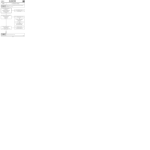
15-way connector (A)
13825R
Track Description
1 Not used
2 AC operating information
3 Recirculation on/off
4 AC computer earth
5 + 12 V accessories (fan assembly fuse)
6 + 12 V after ignition (brake fuse)
7 Not used
8 Not used
9 Not used
10 Not used
11 Not used
12 Not used
13 Not used
14 Not used
15 Not used
62-61


,
- the two pressure relief")


13825R
Track Description
1 Not used
2 AC operating information
3 Recirculation on/off
4 AC computer earth
5 + 12 V accessories (fan assembly fuse)
6 +")