Page 9 of 73
HEATING
Air distribution unit
61
12969-1R
12965-1R
- the visor and the instrument panel,
- the switch stalk block assembly.
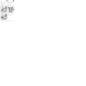
REMOVAL
Disconnect the battery.
Remove :
- the steering wheel bolt,
- the steering wheel after first placing the wheels
in a straight line.
ATTENTION: Follow the recommendations contai-
ned in section 88 relating to the AIR BAG system.
Remove :
- the steering wheel half-shell cowlings,Using adhesive tape, immobilise the rotor for the
air bag switch.
Remove :
- the ashtray,
- the two screws securing the heater control pa-
nel,
- the fuse holder plate securing screws (five
screws),
- the dashboard mounting nuts.
Unclip the wiring from the dashboard.
Remove the dashboard.
12971R
61-6
Page 10 of 73
HEATING
Air distribution unit
61
13084S
13069R3
13085S
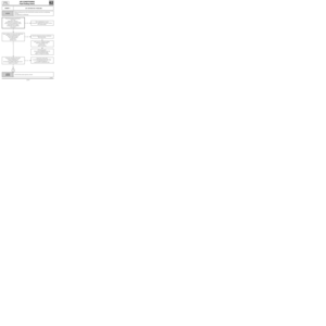
Other type of quick-release clamps. Engine compartment end
Fit a hose clamp and disconnect the quick-release
clamps from the heater hoses.Fit a deflector and blow out the remaining liquid
using compressed air.
Remove :
- the flange bolt from the heater pipes,
- the windscreen wiper arms using tool
Elé. 1294-01,
- the upper seal for the plenum chamber as well
as the external air intake grille,
- the blown air unit,
- the air distribution unit mounting bolt.
61-7
Page 11 of 73

HEATING
Air distribution unit
61
PRO61.3
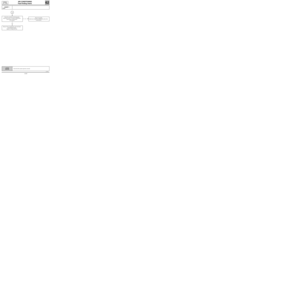
In the passenger compartment
Remove :
- the air distribution unit,
- the heater unit radiator.REFITTING
Check :
- that the wiring is correctly routed behind the
dashboard,
- that the air ducts are correctly secured to pre-
vent noises developing.
Change the steering wheel bolt (pre-bonded bolt,
tightening torque : 4.5 daN.m).
IMPORTANT : Before reconnecting the AIR BAG
cushion it is necessary to apply the air bag system
operational check procedure :
• Check that the AIR BAG warning light on the
instrument panel is illuminated when the igni-
tion is switched on.
• Connect an inert ignition unit to the AIR BAG
cushion connector and check that the warning
light extinguishes.
• Switch off the ignition, connect the AIR BAG
cushion in place of the inert ignition unit and
secure the cushion on to the steering wheel.
• Switch on the ignition, check that the air bag
warning light illuminates for three seconds
when the ignition is switched on and then ex-
tinguishes and remains extinguished.
If the warning light does not operate as indicated
above, please consult section 88 of the workshop
repair manual.
61-8
Page 12 of 73
AIR CONDITIONING
General
62
91096-3R1
62-1
Page 13 of 73
AIR CONDITIONING
General
62
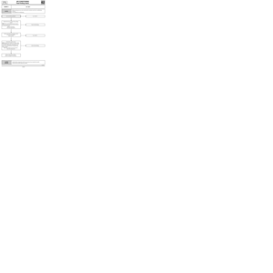
A Passenger compartment
B Engine compartment
C Exterior air
D To air mixing unit
E Scuttle panel grille
F Exterior or recirculated air
1 Compressor with variable capacity
2 Condenser
3 Dehydration canister
4 Pressure sensor
5 High pressure valve
6 Pressure relief valve
7 Evaporator
8 Low pressure valve
9 Heating/ventilation fan
10 Cooling fan
11 Engine radiator
12 High pressure fluid
13 Low pressure vapour
14 High pressure vapour
Consumables:
- Compressor oil
SANDEN SP 10: 135 cm3 ± 15
- Coolant
R134a: 650 g ± 35
- Compressor
SANDEN SD 7V 16
62-2
Page 14 of 73
c11010.0
AIR CONDITIONING
Fault finding - Introduction
62
KANGOO
ALL TYPES
ESTABLISHING XR25 / HEATING-VENTILATION CONTROL UNIT DIALOGUE
- Connect the XR25 to the diagnostic socket.
- ISO selector on S8
- Enter D17 n.61
PRECAUTION :
When carrying out checks using a multimeter, avoid using a contact tip on the connectors the size of which
could damage the clips and result in poor contact.
ERASING THE MEMORY:
After repairing the air conditioning system, enter G0** on the XR25 keypad to erase the fault stored.
62-3
Page 15 of 73
c11010.0
AIR CONDITIONING
Fault finding - XR25 fiche
62
KANGOO
ALL TYPES
PRESENTATION OF XR25 FICHE N° 61
FI21761
62-4
Page 16 of 73

If illuminated, this indicates a fault o")
c11010.0
AIR CONDITIONING
Fault finding - XR25 fiche
62
KANGOO
ALL TYPES
REPRESENTATION OF BARGRAPHS
REPRESENTATION OF FAULTS (always on a coloured background)
If illuminated, this indicates a fault on the component in question, the associated text defines
the fault.
REPRESENTATION OF STATUS (always on a white background)
Illuminates when dialogue is established with the component computer, if it remains
extinguished:
- the code does not exist,
- there is an equipment, computer or line fault.
Engine stopped, ignition on, no operator action
The status bargraphs on the fiche are represented as they should appear with the engine stopped, ignition
on and no operator action.
- If on the fiche, the bargraph is represented the XR25 should display
- If on the fiche, the bargraph is represented the XR25 should display
- If on the fiche, the bargraph is represented the XR25 should display
either or
Engine running
Extinguished when the function or condition described on the fiche is no longer carried out.
Illuminated when the function or condition described on the fiche is carried out.
62-5