Page 57 of 73
AIR CONDITIONING
Wiring diagram
62E7J ENGINE
PRO14441
62-46
Page 58 of 73
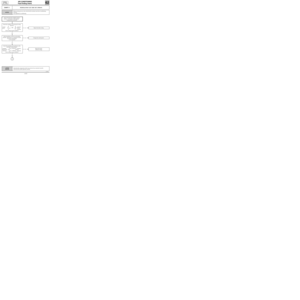
AIR CONDITIONING
Wiring diagram
62
D7F/F8Q and E7J
ENGINES
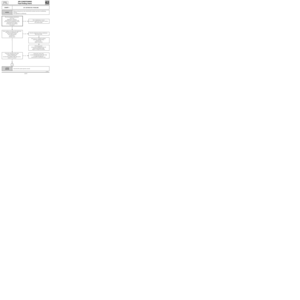
120 Injection computer
171 Air conditioning clutch
206 Air control pressure switch
225 Diagnostic socket
234 Fan assembly relay
236 Fuel pump relay
248 Fan assembly thermal switch
260 Fuse box
319 Air conditioning control panel
320 Base fan assembly/Air conditioning
419 Air conditioning control unit
466 Shunt box
597 Engine fuse box
700 Cooling fan relay (low speed)
R67 Front of engine/Engine
NB : Evaporator sensor (depending on assembly)
62-47
Page 59 of 73

AIR CONDITIONING
Evaporator
62
13831R
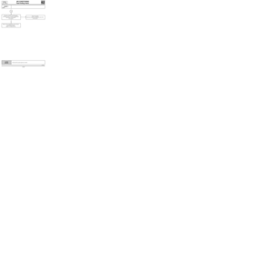
Pressure relief valve to evaporator bolt 0.6
Connecting pipes to pressure relief valve
retaining nut 0.8
Pressure relief valve conne")
TIGHTENING TORQUES (in daN.m)
AIR CONDITIONING
Evaporator
62
13831R
Pressure relief valve to evaporator bolt 0.6
Connecting pipes to pressure relief valve
retaining nut 0.8
Pressure relief valve connecting pipe to
dehydration canister retaining bolt 0.8
Condenser connecting pipe to
dehydration canister retaining bolt 1.2
Compressor connecting pipe to condenser
retaining bolt 0.8
Connecting pipes to compressor
retaining bolt 2.1
Compressor retaining bolt 2.1
Circuit pressure sensor 0.8
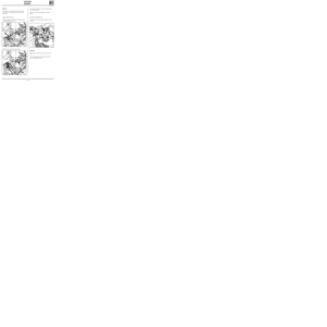
REMOVAL
Disconnect the battery.
Drain the R134a coolant circuit using the filling
equipment.
Disconnect the R134a connecting pipes (bolt 1) to
the pressure relief valve.
Install the plugs on the pipes and the pressure re-
lief valve.Remove:
- the windscreen wiper arms,
- the air inlet grille,
- the six plenum chamber closure panel (2) retai-
ning bolts (A) and remove the plenum cham-
ber,
- the evaporator protector in the plenum cham-
ber.
Disconnect the electrical connectors (4) and the
earth leads (5).
Remove the intermediate sleeve (6) between the
evaporator housing and the heater fan assembly.
13826R
62-48
Page 60 of 73

AIR CONDITIONING
Evaporator
62
Move aside the dashboard by removing:
- the six steering column mounting bolts,
- the four dashboard side retaining nuts and the
two bolts behind the ashtray assembly.
NOTE: take care to protect the sections of the
dashboard which are susceptible to damage using
cloths.
Remove the two evaporator housing mountings
behind the dashboard on the passenger side.
Remove the evaporator housing.
Carefully remove the evaporator from its housing.
REFITTING
Check that the harness tubes are not in contact
(risk of noise).
Proceed in the reverse order to removal.
Tighten the retaining nut (connecting pipes to
pressure relief valve) to 0.8 daN.m (pay attention
to the condition of the seals).
NOTE: when refitting the dashboard, check:
- that the electrical wiring is positioned correctly,
- that the air flow pipes are positioned correctly
(glove box for example).
Create a vacuum, then fill the R134a coolant cir-
cuit using the filling equipment.
IMPORTANT
When an evaporator is changed, add 30 ml of
P.A.G. SP 10 oil to the circuit.
Use the same oil for refitting the seals taking care
to position them correctly.
62-49
Page 61 of 73
AIR CONDITIONING
Air blower unit
62
REMOVAL
An air blower unit can only be changed following
removal of the evaporator (refer to the
"Evaporator" section).
Remove the two heater fan assembly mounting
bolts.
Remove the heater fan assembly.
REFITTING
Refitting does not present any special points.
After refitting the heater fan assembly and the
evaporator, create a vacuum and then fill the
R134a coolant circuit using the filling equipment.
IMPORTANT
Ensure that all of the seals are positioned correct-
ly. Lubricate them with
P.A.G. SP 10 oil.
62-50
Page 62 of 73
,
- the retaining")
AIR CONDITIONING
Compressor
62D7F ENGINE
13829R1
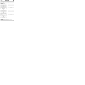
REMOVAL
Drain the R134a coolant circuit.
Disconnect the battery.
Remove:
- the compressor drive belt,
- the two connecting pipes (A),
- the retaining strut bolt (B),
- the three compressor retaining bolts (C).
Remove the compressor.
NOTE: it is essential to place plugs on the pipes
and on the compressor to prevent the entry of hu-
midity into the circuit.
REFITTING
If it is changed, the compressor is supplied filled
with oil.
Position the compressor the correct way round
(filler plug facing upwards).
Tighten the three bolts (C) (Tightening torque:
2.1 daN.m).
Fit the strut retaining bolts (B).
Refit the two R134a coolant pipes (A) on the
compressor (Tightening torque:
2.1 daN.m).
Fit the drive belt and tension it.
Create a vacuum, then fill the R134a coolant cir-
cuit using the filling equipment.
NOTE: when refitting the connecting pipes on the
compressor, it is essential to fit all the bolts, then
bring them into contact before torque tightening
them. The aim is to ensure that the pipe is positio-
ned correctly so that it is not damaged at the cut
off (1).
Check the condition of the seals and lubricate
them with
P.A.G. SP 10 oil.
IMPORTANT
When changing the compressor, it is essential to
top up the oil.
62-51
Page 63 of 73

AIR CONDITIONING
Compressor
62F8Q ENGINE
REMOVAL
Place the vehicle on a lift.
Drain the R134a coolant circuit.
Disconnect the battery.
Remove the front bumper.
From above, remove:
- the compressor drive belt,
- the two connecting pipes (A),
- the connecting pipe retaining lug (B).
From underneath the vehicle, remove the three
compressor retaining bolts and remove the
compressor.
NOTE: it is essential to fit plugs on the pipes and
on the compressor to prevent humidity from ente-
ring the circuit.
13947R
REFITTING
If it is changed, the compressor is supplied filled
with oil.
Position the compressor the correct way round
(filler plug facing upwards).
Tighten the three bolts (C) (Tightening torque:
2.1 daN.m).
Refit the two R134a coolant pipes (A) on the
compressor (Tightening torque:
2.1 daN.m) as well
as bracket (B).
Fit the drive belt and tension it.
Create a vacuum, then fill the R134a coolant cir-
cuit using the filling equipment.
NOTE: when refitting the connecting pipes on the
compressor, it is essential to fit all the bolts, then
bring them into contact before torque tightening
them. The aim is to ensure that the pipe is positio-
ned correctly so that it is not damaged at the cut
off (1).
Check the condition of the seals and lubricate
them with
P.A.G. SP 10 oil.
IMPORTANT
When changing the compressor, it is essential to
top up the oil.
62-52
Page 64 of 73

AIR CONDITIONING
Compressor
62E7J ENGINE
REMOVAL
Place the vehicle on a lift.
Drain the R134a coolant circuit.
Disconnect the battery.
Remove:
- the engine undertray,
- the bumper.
From above, remove:
- the accessories drive belt,
- the two R134a connecting pipes (A).
From underneath the vehicle, remove:
- the compressor drive belt,
- the compressor retaining bolts and remove the
the compressor.
NOTE: it is essential to fit plugs on the pipes and
on the compressor to prevent humidity from ente-
ring the circuit.
REFITTING
If it is changed, the compressor is supplied filled
with oil.
Position the compressor the correct way round
(filler plug facing upwards).
Tighten the retaining bolts (C) (Tightening tor-
que: 2.1 daN.m).
Refit the two R134a coolant pipes (A) on the
compressor (Tightening torque:
2.1 daN.m).
Fit the drive belts and tension them.
Create a vacuum, then fill the R134a coolant cir-
cuit using the filling equipment.
NOTE: when refitting the connecting pipes on the
compressor, it is essential to fit all the bolts, then
bring them into contact before torque tightening
them. The aim is to ensure that the pipe is positio-
ned correctly so that it is not damaged at the cut
off (1).
Check the condition of the seals and lubricate
them with
P.A.G. SP 10 oil.
IMPORTANT
When changing the compressor, it is essential to
top up the oil.
14229R
62-53


.
Remove the two heater fan assembly mounting")