1998 OPEL FRONTERA battery
[x] Cancel search: batteryPage 5313 of 6000
6A – 40 ENGINE MECHANICAL
REMOVAL
1. Disconnect battery ground cable.
2. Drain engine coolant.
3. Remove air cleaner and air duct.
4. Remove intercooler assembly.
Refer to “Intercooler” in this manual.
5. Remove oil level gauge guide assembly.
6. Remove PCV hose.
7. Remove EGR vacuum hose.
8. Disconnect harness connector around the cylinder
head.
9. Remove A/C compressor assembly.
10. Remove A/C compressor bracket.
11. Remove generator assembly and take out fan belt.
12. Remove heat protector and remove valve
assembly.
13. Remove water hose and oil pipe from turbocharger.
14. Remove turbocharger assembly.
15. Remove water hose between thermostat and
radiator.
16. Remove cylinder head noise insulator cover.
NOTE: Do not make damage to the harness.
17. Remove high pressure pipe.
18. Remove timing belt cover.
19. Remove CMP sensor bracket.
20. Remove timing belt tensioner and remove timing
belt.
21. Remove camshaft pulley.
22. Remove front plate.
23. Remove water pipe between cylinder head and
water pump.
24. Remove fuel pipe between fuel pump and intake
manifold.
25. Remove fuel return pipe.
26. Remove intake manifold assembly.
27. Disconnect glow plug wiring and remove glow plug.
28. Remove cylinder head cover.
29. Drain oil from oil rail.
30. Disconnect injector harness connector.
31. Disconnect harness connector from oil pressure
sensor and oil temperature sensor on the oil rail.
32. Disconnect injector harness assembly.
33. Remove injector clamp.
34. Remove injector spacer.
35. Remove injector assembly.
36. Remove oil rail assembly.
37. Remove camshaft carrier.
38. Remove cylinder head assembly.
39. Remove cylinder gasket.
INSTALLATION
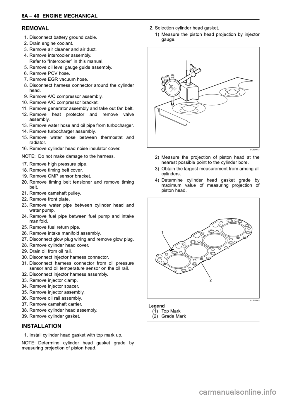
1. Install cylinder head gasket with top mark up.
NOTE: Determine cylinder head gasket grade by
measuring projection of piston head.2. Selection cylinder head gasket.
1) Measure the piston head projection by injector
gauge.
2) Measure the projection of piston head at the
nearest possible point to the cylinder bore.
3) Obtain the largest measurement from among all
cylinders.
4) Determine cylinder head gasket grade by
maximum value of measuring projection of
piston head.
Legend
(1) Top Mark
(2) Grade Mark
012RW073
2 1
011RW043
Page 5315 of 6000

6A – 42 ENGINE MECHANICAL
Legend
(1) Cylinder Head Noise Insulator Cover
(2) Insulator
(3) Bolt
(4) Oil Seal
(5) Gasket
(6) Cylinder Head Cover
(7) Bolt
21. Install water hose between thermostat and radiator.
22. Install turbocharger assembly to exhaust manifold.
Torque: 27 Nꞏm (2.8 kgꞏm/20.2 lb ft)
23. Install water hose and oil pipe for turbocharger.
24. Install exhaust valve assembly and heat protector.
Torque: 27 Nꞏm (2.8 kgꞏm/20.2 lb ft) for valve
Torque: 9 Nꞏm (0.9 kgꞏm/6.5 lb ft) for heat protector25. Install generator assembly.
Torque: 40 Nꞏm (4.0 kgꞏm/29 lb ft) for ACG bracket
Torque: 40 Nꞏm (4.0 kgꞏm/29 lb ft) between ACG and
bracket
Torque: 20 Nꞏm (2.0 kgꞏm/14.5 lb ft) between ACG
and adjuster plate
26.Fix the A/C compressor bracket and install A/C
compressor.
Torque: 47 Nꞏm (4.7 kgꞏm/34 lb ft) for A/C bracket
Torque: 20 Nꞏm (2.0 kgꞏm/14.5 lb ft) for belt tensioner
27. Reconnect harness connector around cylinder
head.
28. Connect EGR vacuum hose.
29. Install oil level gauge guide assembly.
Tighten nuts lower portion and tighten bolt.
Torque: 20 Nꞏm (2.0 kgꞏm/14.5 lb ft)
30. Install intercooler assembly.
Refer to “Intercooler” in this manual.
31. Install air duct between air cleaner and
turbocharger.
32. Fill engine coolant.
33. Reconnect battery.
036RW005
036RW006
1
2
3 7
4
5 6
010RW010
Page 5329 of 6000
6A – 56 ENGINE MECHANICAL
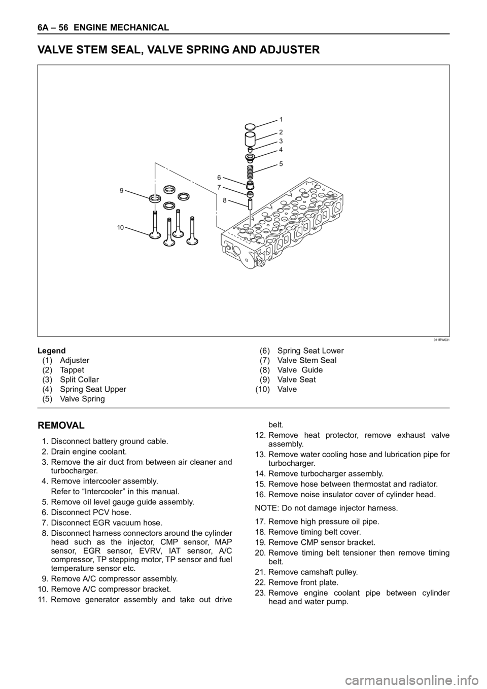
VALVE STEM SEAL, VALVE SPRING AND ADJUSTER
REMOVAL
1. Disconnect battery ground cable.
2. Drain engine coolant.
3. Remove the air duct from between air cleaner and
turbocharger.
4. Remove intercooler assembly.
Refer to “Intercooler” in this manual.
5. Remove oil level gauge guide assembly.
6. Disconnect PCV hose.
7. Disconnect EGR vacuum hose.
8. Disconnect harness connectors around the cylinder
head such as the injector, CMP sensor, MAP
sensor, EGR sensor, EVRV, IAT sensor, A/C
compressor, TP stepping motor, TP sensor and fuel
temperature sensor etc.
9. Remove A/C compressor assembly.
10. Remove A/C compressor bracket.
11. Remove generator assembly and take out drivebelt.
12. Remove heat protector, remove exhaust valve
assembly.
13. Remove water cooling hose and lubrication pipe for
turbocharger.
14. Remove turbocharger assembly.
15. Remove hose between thermostat and radiator.
16. Remove noise insulator cover of cylinder head.
NOTE: Do not damage injector harness.
17. Remove high pressure oil pipe.
18. Remove timing belt cover.
19. Remove CMP sensor bracket.
20. Remove timing belt tensioner then remove timing
belt.
21. Remove camshaft pulley.
22. Remove front plate.
23. Remove engine coolant pipe between cylinder
head and water pump.
1
2
3
4
5
6
9
10
7
8
011RW031
Legend
(1) Adjuster
(2) Tappet
(3) Split Collar
(4) Spring Seat Upper
(5) Valve Spring(6) Spring Seat Lower
(7) Valve Stem Seal
(8) Valve Guide
(9) Valve Seat
(10) Valve
Page 5335 of 6000
6A – 62 ENGINE MECHANICAL
INSTALLATION
1. Valve stem seal
1) Use the special tool to install the stem seal to the
valve guide.
Stem Seal Installer: 5-8840-2033-0
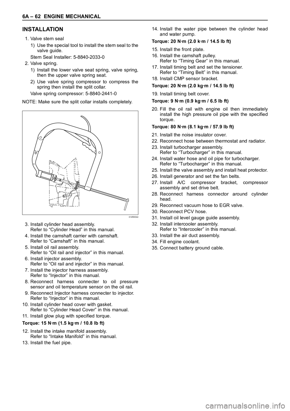
2. Valve spring.
1) Install the lower valve seat spring, valve spring,
then the upper valve spring seat.
2) Use valve spring compressor to compress the
spring then install the split collar.
Valve spring compressor: 5-8840-2441-0
NOTE: Make sure the split collar installs completely.
3. Install cylinder head assembly.
Refer to “Cylinder Head” in this manual.
4. Install the camshaft carrier with camshaft.
Refer to “Camshaft” in this manual.
5. Install oil rail assembly.
Refer to “Oil rail and injector” in this manual.
6. Install injector assembly.
Refer to “Oil rail and injector” in this manual.
7. Install the injector harness assembly.
Refer to “Injector” in this manual.
8. Reconnect harness connecter to oil pressure
sensor and oil temperature sensor on the oil rail.
9. Reconnect Injector harness connecter to injector.
Refer to “Injector” in this manual.
10. Install cylinder head cover with gasket.
Refer to “Cylinder Head Cover” in this manual.
11. Install glow plug with specified torque.
Torque: 15 Nꞏm (1.5 kgꞏm / 10.8 lb ft)
12. Install the intake manifold assembly.
Refer to “Intake Manifold” in this manual.
13. Install the fuel pipe.14. Install the water pipe between the cylinder head
and water pump.
Torque: 20 Nꞏm (2.0 kꞏm / 14.5 lb ft)
15. Install the front plate.
16. Install the camshaft pulley.
Refer to “Timing Gear” in this manual.
17. Install timing belt and set the tensioner.
Refer to “Timing Belt” in this manual.
18. Install CMP sensor bracket.
Torque: 20 Nꞏm (2.0 kgꞏm / 14.5 lb ft)
19. Install timing belt cover.
Torque: 9 Nꞏm (0.9 kgꞏm / 6.5 lb ft)
20. Fill the oil rail with engine oil then immediately
install the high pressure oil pipe with the specified
torque.
Torque: 80 Nꞏm (8.1 kgꞏm / 57.9 lb ft)
21. Install the noise insulator cover.
22. Reconnect hose between thermostat and radiator.
23. Install turbocharger assembly.
Refer to “Turbocharger” in this manual.
24. Install water hose and oil pipe for turbocharger.
Refer to “Turbocharger” in this manual.
25. Install the valve assembly and install heat protector.
26. Install generator and set the fan belts.
27. Install A/C compressor bracket, compressor
assembly and set drive belt.
28. Reconnect harness connector around cylinder
head.
29. Reconnect vacuum hose to EGR valve.
30. Reconnect PCV hose.
31. Install oil level gauge guide assembly.
32. Install intercooler assembly.
Refer to “Intercooler” in this manual.
33. Install the air duct assembly.
34. Fill engine coolant.
35. Connect battery ground cable.
014RW042
Page 5338 of 6000
ENGINE MECHANICAL 6A – 65
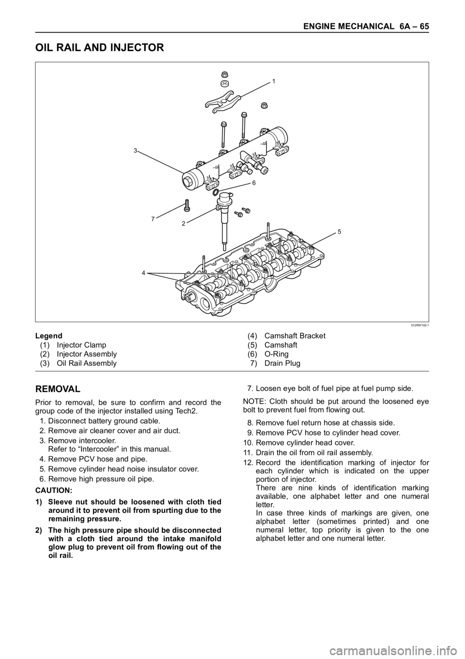
OIL RAIL AND INJECTOR
REMOVAL
Prior to removal, be sure to confirm and record the
group code of the injector installed using Tech2.
1. Disconnect battery ground cable.
2. Remove air cleaner cover and air duct.
3. Remove intercooler.
Refer to “Intercooler” in this manual.
4. Remove PCV hose and pipe.
5. Remove cylinder head noise insulator cover.
6. Remove high pressure oil pipe.
CAUTION:
1) Sleeve nut should be loosened with cloth tied
around it to prevent oil from spurting due to the
remaining pressure.
2) The high pressure pipe should be disconnected
with a cloth tied around the intake manifold
glow plug to prevent oil from flowing out of the
oil rail.7. Loosen eye bolt of fuel pipe at fuel pump side.
NOTE: Cloth should be put around the loosened eye
bolt to prevent fuel from flowing out.
8. Remove fuel return hose at chassis side.
9. Remove PCV hose to cylinder head cover.
10. Remove cylinder head cover.
11. Drain the oil from oil rail assembly.
12. Record the identification marking of injector for
each cylinder which is indicated on the upper
portion of injector.
There are nine kinds of identification marking
available, one alphabet letter and one numeral
letter.
In case three kinds of markings are given, one
alphabet letter (sometimes printed) and one
numeral letter, top priority is given to the one
alphabet letter and one numeral letter.
1
6
27
3
5
4
012RW102-1
Legend
(1) Injector Clamp
(2) Injector Assembly
(3) Oil Rail Assembly(4) Camshaft Bracket
(5) Camshaft
(6) O-Ring
7) Drain Plug
Page 5367 of 6000
6A – 94 ENGINE MECHANICAL
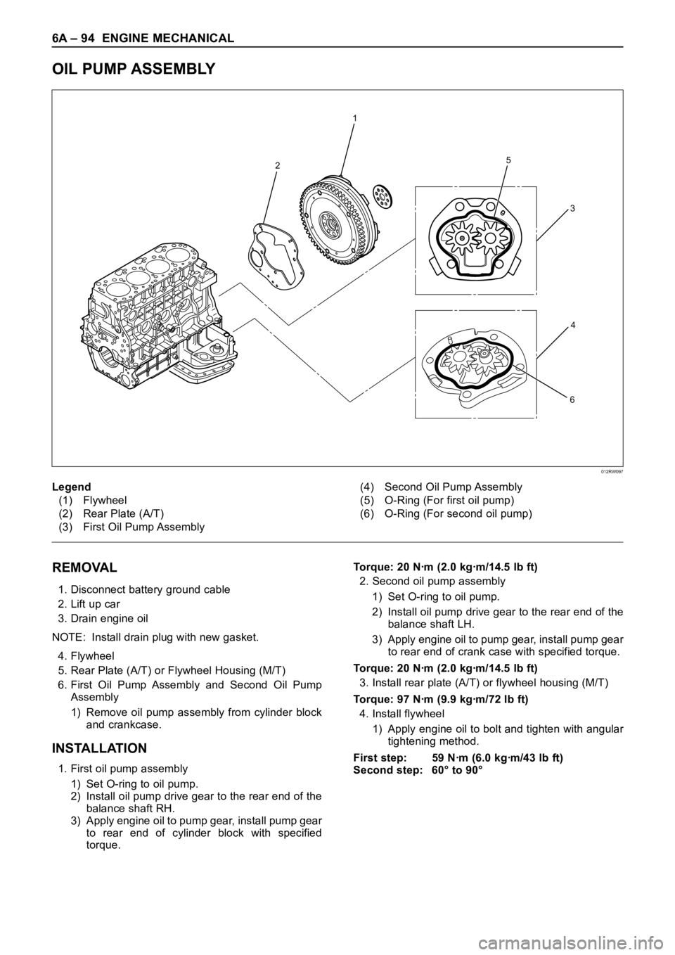
OIL PUMP ASSEMBLY
2
1
5
6
3
4
012RW097
Legend
(1) Flywheel
(2) Rear Plate (A/T)
(3) First Oil Pump Assembly(4) Second Oil Pump Assembly
(5) O-Ring (For first oil pump)
(6) O-Ring (For second oil pump)
REMOVAL
1. Disconnect battery ground cable
2. Lift up car
3. Drain engine oil
NOTE: Install drain plug with new gasket.
4. Flywheel
5. Rear Plate (A/T) or Flywheel Housing (M/T)
6. First Oil Pump Assembly and Second Oil Pump
Assembly
1) Remove oil pump assembly from cylinder block
and crankcase.
INSTALLATION
1. First oil pump assembly
1) Set O-ring to oil pump.
2) Install oil pump drive gear to the rear end of the
balance shaft RH.
3) Apply engine oil to pump gear, install pump gear
to rear end of cylinder block with specified
torque.Torque: 20 Nꞏm (2.0 kgꞏm/14.5 lb ft)
2. Second oil pump assembly
1) Set O-ring to oil pump.
2) Install oil pump drive gear to the rear end of the
balance shaft LH.
3) Apply engine oil to pump gear, install pump gear
to rear end of crank case with specified torque.
Torque: 20 Nꞏm (2.0 kgꞏm/14.5 lb ft)
3. Install rear plate (A/T) or flywheel housing (M/T)
Torque: 97 Nꞏm (9.9 kgꞏm/72 lb ft)
4. Install flywheel
1) Apply engine oil to bolt and tighten with angular
tightening method.
First step: 59 Nꞏm (6.0 kgꞏm/43 lb ft)
Second step: 60° to 90°
Page 5369 of 6000

6A – 96 ENGINE MECHANICAL
REMOVAL
1. Disconnect battery ground cable
2. Drain engine coolant
3. Remove front exhaust pipe
4. Remove heat protector
5. Remove exhaust valve assembly
6. Oil cooler assembly
1) Remove water hoses from inlet and outlet pipe.
2) Put rag beneath side of oil cooler to prevent oil
leaking.
3) Remove fixing bolts and oil cooler assembly.
INSTALLATION
1. Oil Cooler
1) Tighten oil cooler fixing bolt to the specified
torque and connect water hose.
Torque: 29 Nꞏm (3.0 kgꞏm/22 lb ft)
2. Exh. Valve Assembly
1) Install exhaust valve assembly with gasket and
tighten fixing bolts to the specified torque.
Torque: 27 Nꞏm (2.7 kgꞏm/20 lb ft)
3. Heat Protector
4. Front Exhaust Pipe
1) Install front exhaust pipe and tighten fixing bolts
to the specified torque.
Exh. Valve Side: 67 Nꞏm (6.8 kgꞏm/50 lb ft)
Intermediate Pipe Side: 43 Nꞏm (4.4 kgꞏm/32 lb ft)
5. Fill engine coolant.
6. Connect battery ground cable.
7. Start engine and check for oil and water leakage
carefully.
Page 5376 of 6000
ENGINE COOLING 6B – 7
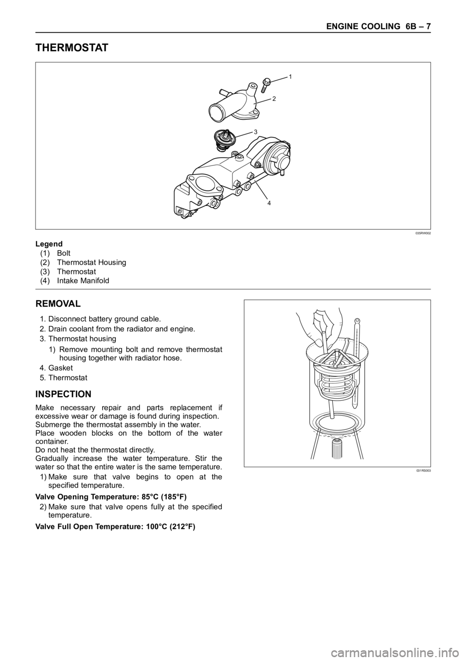
THERMOSTAT
REMOVAL
1. Disconnect battery ground cable.
2. Drain coolant from the radiator and engine.
3. Thermostat housing
1) Remove mounting bolt and remove thermostat
housing together with radiator hose.
4. Gasket
5. Thermostat
INSPECTION
Make necessary repair and parts replacement if
excessive wear or damage is found during inspection.
Submerge the thermostat assembly in the water.
Place wooden blocks on the bottom of the water
container.
Do not heat the thermostat directly.
Gradually increase the water temperature. Stir the
water so that the entire water is the same temperature.
1) Make sure that valve begins to open at the
specified temperature.
Valve Opening Temperature: 85°C (185°F)
2) Make sure that valve opens fully at the specified
temperature.
Valve Full Open Temperature: 100°C (212°F)
1
2
3
4
Legend
(1) Bolt
(2) Thermostat Housing
(3) Thermostat
(4) Intake Manifold
035RW002
031RS003