1998 OPEL FRONTERA cruise control
[x] Cancel search: cruise controlPage 4965 of 6000
6E–308
ENGINE DRIVEABILITY AND EMISSIONS
Accelerator Pedal Replacement
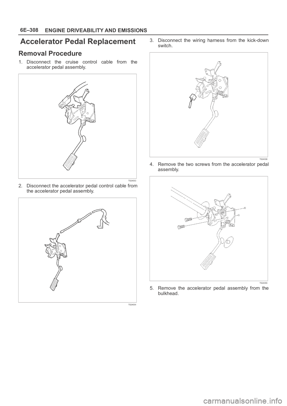
Removal Procedure
1. Disconnect the cruise control cable from the
accelerator pedal assembly.
TS24053
2. Disconnect the accelerator pedal control cable from
the accelerator pedal assembly.
TS24054
3. Disconnect the wiring harness from the kick-down
switch.
TS24038
4. Remove the two screws from the accelerator pedal
assembly.
TS24055
5. Remove the accelerator pedal assembly from the
bulkhead.
Page 4966 of 6000
6E–309 ENGINE DRIVEABILITY AND EMISSIONS
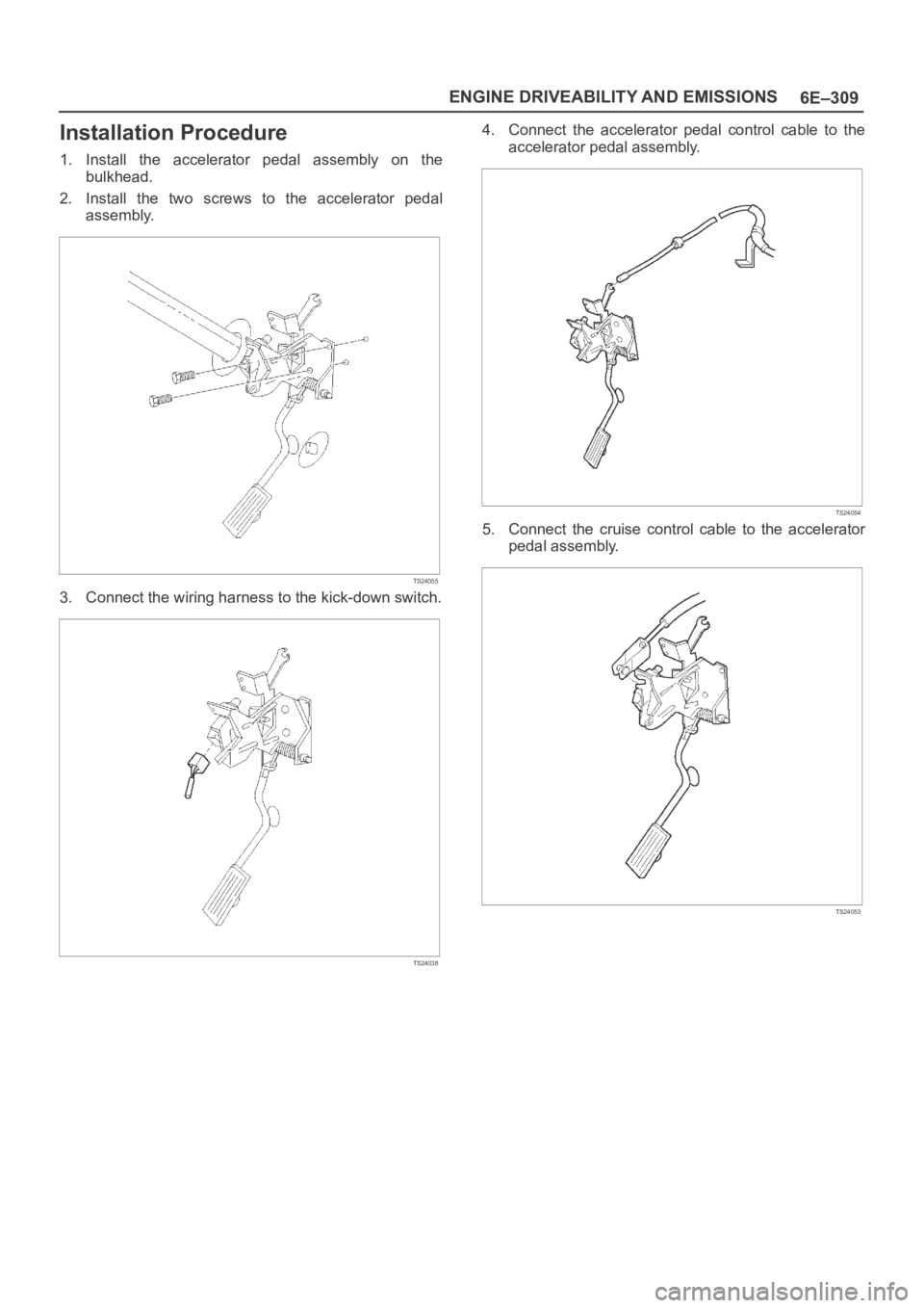
Installation Procedure
1. Install the accelerator pedal assembly on the
bulkhead.
2. Install the two screws to the accelerator pedal
assembly.
TS24055
3. Connect the wiring harness to the kick-down switch.
TS24038
4. Connect the accelerator pedal control cable to the
accelerator pedal assembly.
TS24054
5. Connect the cruise control cable to the accelerator
pedal assembly.
TS24053
Page 4996 of 6000
6E–339 ENGINE DRIVEABILITY AND EMISSIONS
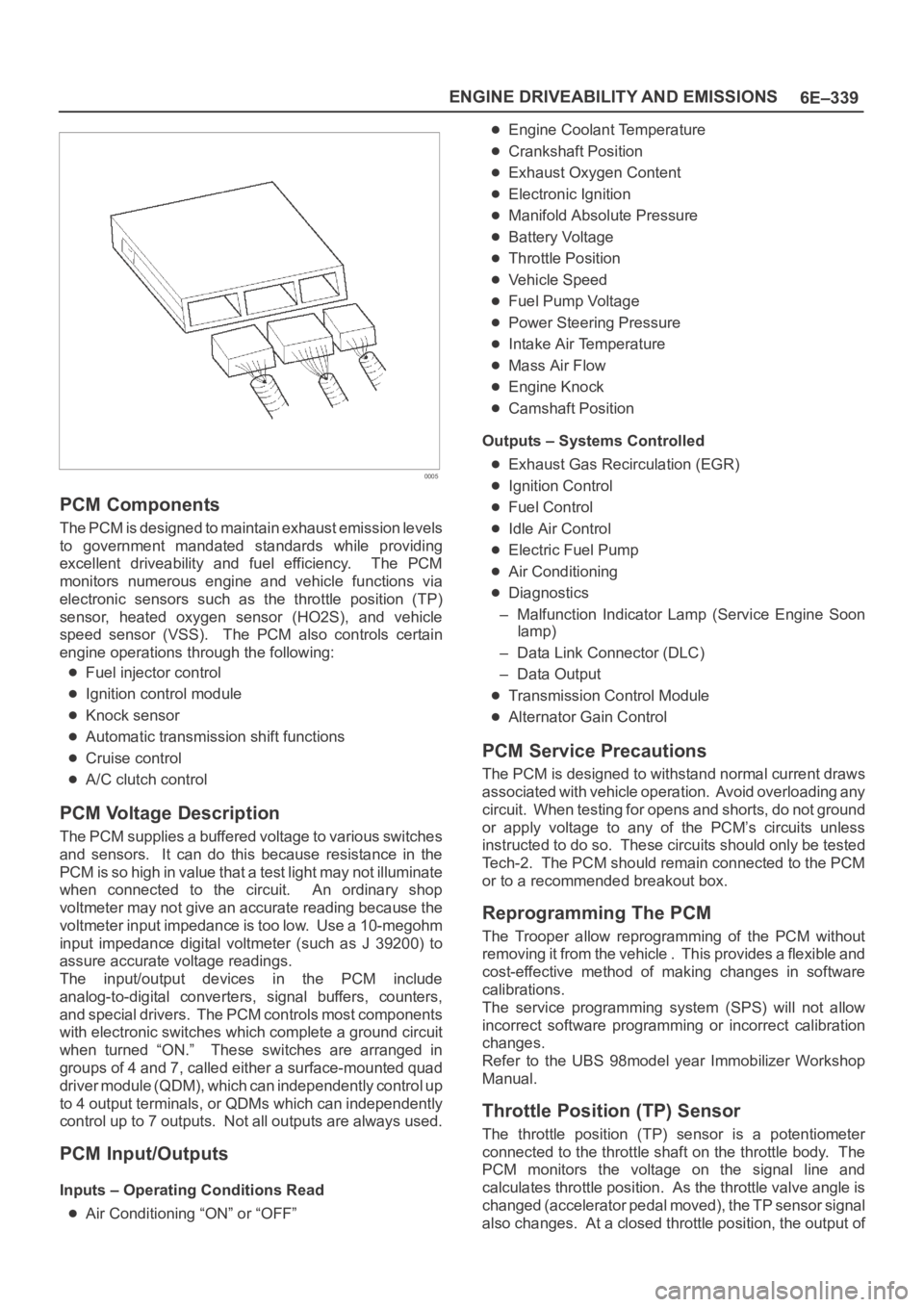
0005
PCM Components
The PCM is designed to maintain exhaust emission levels
to government mandated standards while providing
excellent driveability and fuel efficiency. The PCM
monitors numerous engine and vehicle functions via
electronic sensors such as the throttle position (TP)
sensor, heated oxygen sensor (HO2S), and vehicle
speed sensor (VSS). The PCM also controls certain
engine operations through the following:
Fuel injector control
Ignition control module
Knock sensor
Automatic transmission shift functions
Cruise control
A/C clutch control
PCM Voltage Description
The PCM supplies a buffered voltage to various switches
and sensors. It can do this because resistance in the
PCM is so high in value that a test light may not illuminate
when connected to the circuit. An ordinary shop
voltmeter may not give an accurate reading because the
voltmeter input impedance is too low. Use a 10-megohm
input impedance digital voltmeter (such as J 39200) to
assure accurate voltage readings.
The input/output devices in the PCM include
analog-to-digital converters, signal buffers, counters,
and special drivers. The PCM controls most components
with electronic switches which complete a ground circuit
when turned “ON.” These switches are arranged in
groups of 4 and 7, called either a surface-mounted quad
driver module (QDM), which can independently control up
to 4 output terminals, or QDMs which can independently
control up to 7 outputs. Not all outputs are always used.
PCM Input/Outputs
Inputs – Operating Conditions Read
Air Conditioning “ON” or “OFF”
Engine Coolant Temperature
Crankshaft Position
Exhaust Oxygen Content
Electronic Ignition
Manifold Absolute Pressure
Battery Voltage
Throttle Position
Vehicle Speed
Fuel Pump Voltage
Power Steering Pressure
Intake Air Temperature
Mass Air Flow
Engine Knock
Camshaft Position
Outputs – Systems Controlled
Exhaust Gas Recirculation (EGR)
Ignition Control
Fuel Control
Idle Air Control
Electric Fuel Pump
Air Conditioning
Diagnostics
– Malfunction Indicator Lamp (Service Engine Soon
lamp)
– Data Link Connector (DLC)
– Data Output
Transmission Control Module
Alternator Gain Control
PCM Service Precautions
The PCM is designed to withstand normal current draws
associated with vehicle operation. Avoid overloading any
circuit. When testing for opens and shorts, do not ground
or apply voltage to any of the PCM’s circuits unless
instructed to do so. These circuits should only be tested
Tech-2. The PCM should remain connected to the PCM
or to a recommended breakout box.
Reprogramming The PCM
The Trooper allow reprogramming of the PCM without
removing it from the vehicle . This provides a flexible and
cost-effective method of making changes in software
calibrations.
The service programming system (SPS) will not allow
incorrect software programming or incorrect calibration
changes.
Refer to the UBS 98model year Immobilizer Workshop
Manual.
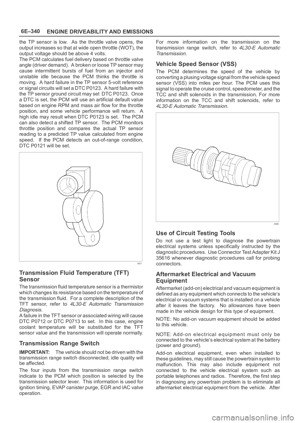
Throttle Position (TP) Sensor
The throttle position (TP) sensor is a potentiometer
connected to the throttle shaft on the throttle body. The
PCM monitors the voltage on the signal line and
calculates throttle position. As the throttle valve angle is
changed (accelerator pedal moved), the TP sensor signal
also changes. At a closed throttle position, the output of
Page 4997 of 6000
6E–340
ENGINE DRIVEABILITY AND EMISSIONS
the TP sensor is low. As the throttle valve opens, the
output increases so that at wide open throttle (WOT), the
output voltage should be above 4 volts.
The PCM calculates fuel delivery based on throttle valve
angle (driver demand). A broken or loose TP sensor may
cause intermittent bursts of fuel from an injector and
unstable idle because the PCM thinks the throttle is
moving. A hard failure in the TP sensor 5-volt reference
or signal circuits will set a DTC P0123. A hard failure with
the TP sensor ground circuit may set DTC P0123. Once
a DTC is set, the PCM will use an artificial default value
based on engine RPM and mass air flow for the throttle
position, and some vehicle performance will return. A
high idle may result when DTC P0123 is set. The PCM
can also detect a shifted TP sensor. The PCM monitors
throttle position and compares the actual TP sensor
reading to a predicted TP value calculated from engine
speed. If the PCM detects an out-of-range condition,
DTC P0121 will be set.
0021
Transmission Fluid Temperature (TFT)
Sensor
The transmission fluid temperature sensor is a thermistor
which changes its resistance based on the temperature of
the transmission fluid. For a complete description of the
TFT sensor, refer to
4L30-E Automatic Transmission
Diagnosis
.
A failure in the TFT sensor or associated wiring will cause
DTC P0712 or DTC P0713 to set. In this case, engine
coolant temperature will be substituted for the TFT
sensor value and the transmission will operate normally.
Transmission Range Switch
IMPORTANT:The vehicle should not be driven with the
transmission range switch disconnected; idle quality will
be affected.
The four inputs from the transmission range switch
indicate to the PCM which position is selected by the
transmission selector lever. This information is used for
ignition timing, EVAP canister purge, EGR and IAC valve
operation.For more information on the transmission on the
transmission range switch, refer to
4L30-E Automatic
Transmission
.
Vehicle Speed Sensor (VSS)
The PCM determines the speed of the vehicle by
converting a plusing voltage signal from the vehicle speed
sensor (VSS) into miles per hour. The PCM uses this
signal to operate the cruise control, speedometer, and the
TCC and shift solenoids in the transmission. For more
information on the TCC and shift solenoids, refer to
4L30-E Automatic Transmission.
0008
Use of Circuit Testing Tools
Do not use a test light to diagnose the powertrain
electrical systems unless specifically instructed by the
diagnostic procedures. Use Connector Test Adapter Kit J
35616 whenever diagnostic procedures call for probing
connectors.
Aftermarket Electrical and Vacuum
Equipment
Aftermarket (add-on) electrical and vacuum equipment is
defined as any equipment which connects to the vehicle’s
electrical or vacuum systems that is installed on a vehicle
after it leaves the factory. No allowances have been
made in the vehicle design for this type of equipment.
NOTE: No add-on vacuum equipment should be added
to this vehicle.
NOTE: Add-on electrical equipment must only be
connected to the vehicle’s electrical system at the battery
(power and ground).
Add-on electrical equipment, even when installed to
these guidelines, may still cause the powertrain system to
malfunction. This may also include equipment not
connected to the vehicle electrical system such as
portable telephones and radios. Therefore, the first step
in diagnosing any powertrain problem is to eliminate all
aftermarket electrical equipment from the vehicle. After
Page 5007 of 6000
6E–350
ENGINE DRIVEABILITY AND EMISSIONS
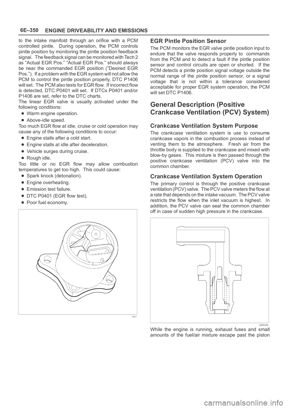
to the intake manifold through an orifice with a PCM
controlled pintle. During operation, the PCM controls
pintle position by monitoring the pintle position feedback
signal. The feedback signal can be monitored with Tech 2
as “Actual EGR Pos.” “Actual EGR Pos.” should always
be near the commanded EGR position (”Desired EGR
Pos.”). If a problem with the EGR system will not allow the
PCM to control the pintle position properly, DTC P1406
will set. The PCM also tests for EGR flow. If incorrect flow
is detected, DTC P0401 will set. If DTCs P0401 and/or
P1406 are set, refer to the DTC charts.
The linear EGR valve is usually activated under the
following conditions:
Warm engine operation.
Above-idle speed.
Too much EGR flow at idle, cruise or cold operation may
cause any of the following conditions to occur:
Engine stalls after a cold start.
Engine stalls at idle after deceleration.
Vehicle surges during cruise.
Rough idle.
Too little or no EGR flow may allow combustion
temperatures to get too high. This could cause:
Spark knock (detonation).
Engine overheating.
Emission test failure.
DTC P0401 (EGR flow test).
Poor fuel economy.
0017
EGR Pintle Position Sensor
The PCM monitors the EGR valve pintle position input to
endure that the valve responds properly to commands
from the PCM and to detect a fault if the pintle position
sensor and control circuits are open or shorted. If the
PCM detects a pintle position signal voltage outside the
normal range of the pintle position sensor, or a signal
voltage that is not within a tolerance considered
acceptable for proper EGR system operation, the PCM
will set DTC P1406.
General Description (Positive
Crankcase Ventilation (PCV) System)
Crankcase Ventilation System Purpose
The crankcase ventilation system is use to consume
crankcase vapors in the combustion process instead of
venting them to the atmosphere. Fresh air from the
throttle body is supplied to the crankcase and mixed with
blow-by gases. This mixture is then passed through the
positive crankcase ventilation (PCV) valve into the
common chamber.
Crankcase Ventilation System Operation
The primary control is through the positive crankcase
v e n t i l a t i o n ( P C V ) v a l v e . T h e PCV valve meters the flow at
a rate that depends on the intake vacuum. The PCV valve
restricts the flow when the inlet vacuum is highest. In
addition, the PCV valve can seal the common chamber
off in case of sudden high pressure in the crankcase.
028RV002
While the engine is running, exhaust fuses and small
amounts of the fuel/air mixture escape past the piston
Page 5582 of 6000
6E–153 4JX1–TC ENGINE DRIVEABILITY AND EMISSIONS
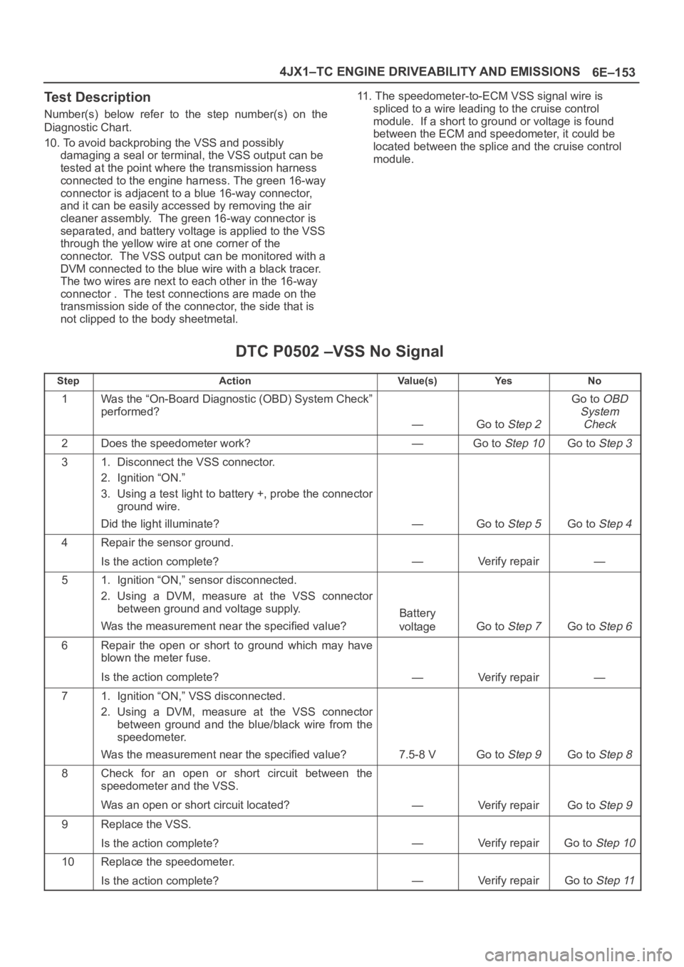
Test Description
Number(s) below refer to the step number(s) on the
Diagnostic Chart.
10. To avoid backprobing the VSS and possibly
damaging a seal or terminal, the VSS output can be
tested at the point where the transmission harness
connected to the engine harness. The green 16-way
connector is adjacent to a blue 16-way connector,
and it can be easily accessed by removing the air
cleaner assembly. The green 16-way connector is
separated, and battery voltage is applied to the VSS
through the yellow wire at one corner of the
connector. The VSS output can be monitored with a
DVM connected to the blue wire with a black tracer.
The two wires are next to each other in the 16-way
connector . The test connections are made on the
transmission side of the connector, the side that is
not clipped to the body sheetmetal.11. The speedometer-to-ECM VSS signal wire is
spliced to a wire leading to the cruise control
module. If a short to ground or voltage is found
between the ECM and speedometer, it could be
located between the splice and the cruise control
module.
DTC P0502 –VSS No Signal
StepActionVa l u e ( s )Ye sNo
1Was the “On-Board Diagnostic (OBD) System Check”
performed?
—Go to Step 2
Go to OBD
System
Check
2Does the speedometer work?—Go to Step 10Go to Step 3
31. Disconnect the VSS connector.
2. Ignition “ON.”
3. Using a test light to battery +, probe the connector
ground wire.
Did the light illuminate?
—Go to Step 5Go to Step 4
4Repair the sensor ground.
Is the action complete?
—Verify repair—
51. Ignition “ON,” sensor disconnected.
2. Using a DVM, measure at the VSS connector
between ground and voltage supply.
Was the measurement near the specified value?
Battery
voltage
Go to Step 7Go to Step 6
6Repair the open or short to ground which may have
blown the meter fuse.
Is the action complete?
—Verify repair—
71. Ignition “ON,” VSS disconnected.
2. Using a DVM, measure at the VSS connector
between ground and the blue/black wire from the
speedometer.
Was the measurement near the specified value?
7.5-8 VGo to Step 9Go to Step 8
8Check for an open or short circuit between the
speedometer and the VSS.
Was an open or short circuit located?
—Verify repairGo to Step 9
9Replace the VSS.
Is the action complete?
—Verify repairGo to Step 10
10Replace the speedometer.
Is the action complete?
—Verify repairGo to Step 11
Page 5608 of 6000
6E–179 4JX1–TC ENGINE DRIVEABILITY AND EMISSIONS
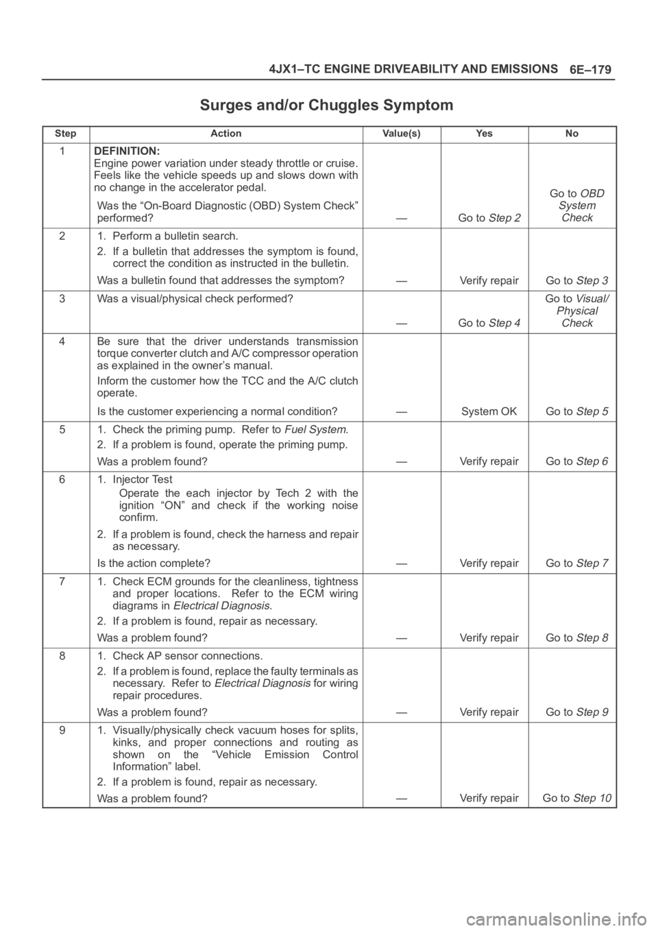
Surges and/or Chuggles Symptom
StepActionVa l u e ( s )Ye sNo
1DEFINITION:
Engine power variation under steady throttle or cruise.
Feels like the vehicle speeds up and slows down with
no change in the accelerator pedal.
Was the “On-Board Diagnostic (OBD) System Check”
performed?
—Go to Step 2
Go to OBD
System
Check
21. Perform a bulletin search.
2. If a bulletin that addresses the symptom is found,
correct the condition as instructed in the bulletin.
Was a bulletin found that addresses the symptom?
—Verify repairGo to Step 3
3Was a visual/physical check performed?
—Go to Step 4
Go to Visual/
Physical
Check
4Be sure that the driver understands transmission
torque converter clutch and A/C compressor operation
as explained in the owner’s manual.
Inform the customer how the TCC and the A/C clutch
operate.
Is the customer experiencing a normal condition?
—System OKGo to Step 5
51. Check the priming pump. Refer to Fuel System.
2. If a problem is found, operate the priming pump.
Was a problem found?
—Verify repairGo to Step 6
61. Injector Test
Operate the each injector by Tech 2 with the
ignition “ON” and check if the working noise
confirm.
2. If a problem is found, check the harness and repair
as necessary.
Is the action complete?
—Verify repairGo to Step 7
71. Check ECM grounds for the cleanliness, tightness
and proper locations. Refer to the ECM wiring
diagrams in
Electrical Diagnosis.
2. If a problem is found, repair as necessary.
Was a problem found?
—Verify repairGo to Step 8
81. Check AP sensor connections.
2. If a problem is found, replace the faulty terminals as
necessary. Refer to
Electrical Diagnosis for wiring
repair procedures.
Was a problem found?
—Verify repairGo to Step 9
91. Visually/physically check vacuum hoses for splits,
kinks, and proper connections and routing as
shown on the “Vehicle Emission Control
Information” label.
2. If a problem is found, repair as necessary.
Was a problem found?
—Verify repairGo to Step 10