Page 2179 of 6000
7A–25 AUTOMATIC TRANSMISSION (4L30–E)
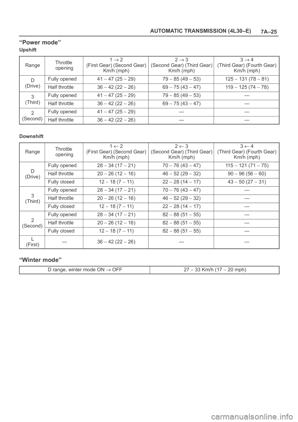
“Power mode”
Upshift
Range
Throttle
opening1 2
(First Gear) (Second Gear)
Km/h (mph)2 3
(Second Gear) (Third Gear)
Km/h (mph)3 4
(Third Gear) (Fourth Gear)
Km/h (mph)
DFully opened41 47 (25 29)79 85 (49 53)125 131 (78 81)
(Drive)Half throttle36 42 (22 26)69 75 (43 47)11 9 125 (74 78)
3Fully opened41 47 (25 29)79 85 (49 53)—
(Third)Half throttle36 42 (22 26)69 75 (43 47)—
2Fully opened41 47 (25 29)——
(Second)Half throttle36 42 (22 26)——
Downshift
Range
Throttle
opening1 2
(First Gear) (Second Gear)
Km/h (mph)2 3
(Second Gear) (Third Gear)
Km/h (mph)3 4
(Third Gear) (Fourth Gear)
Km/h (mph)
D
Fully opened28 34 (17 21)70 76 (43 47)11 5 121 (71 75)
D
(Drive)Half throttle20 26 (12 16)46 52 (29 32)90 96 (56 60)(Drive)
Fully closed12 18 (7 11)22 28 (14 17)43 50 (27 31)
3
Fully opened28 34 (17 21)70 76 (43 47)—
3
(Third)Half throttle20 26 (12 16)46 52 (29 32)—(Third)
Fully closed12 18 (7 11)22 28 (14 17)—
2
Fully opened28 34 (17 21)82 88 (51 55)—
2
(Second)Half throttle20 26 (12 16)82 88 (51 55)—(Second)
Fully closed12 18 (7 11)82 88 (51 55)—
L
(First)—36 42 (22 26)——
“Winter mode”
D range, winter mode ON OFF27 33 Km/h (17 20 mph)
Page 2180 of 6000
7A–26
AUTOMATIC TRANSMISSION (4L30–E)
Lockup Speed Chart
Transfer gear ratio:High: 1.000
Rear axle ratio:4.555
Lockup ONLockup OFF
D range Throttle
i6%
Mode2nd
Km/h
(mph)3rd
Km/h
(mph)4th
Km/h
(mph)2nd
Km/h
(mph)3rd
Km/h
(mph)4th
Km/h
(mph)
opening 6%Normal69 75
(43
47)
63 69
(39
43)
70 76
(43
47)
64 70
(40
43)
43 49
(27
30)
65 71
(40
44)
Power69 75
(43
47)
73 79
(45
49)
73 79
(45
49)
64 70
(40
43)
65 71
(40
44)
69 75
(43
47)
Page 2181 of 6000
7A–27 AUTOMATIC TRANSMISSION (4L30–E)
Changing Transmission Fluid
There is no need to change the transmission fluid unless
the transmission is used under one or more of the
following heavy duty conditions.
A. Repeated short trips
B. Driving on rough roads
C. Driving on dusty roads
D. Towing a trailer
If the vehicle is used under these conditions, change the
fluid every 20,000 miles (32,000 km.)
More over, the remaining life percentage of ATF can be
estimated by using Tech 2 as an auxiliary tool to judge the
right time for ATF replacement.
The remaining life percentage is calculated from ATF’S
heat history. When it is close to 0%, ATF replacement is
recommended.
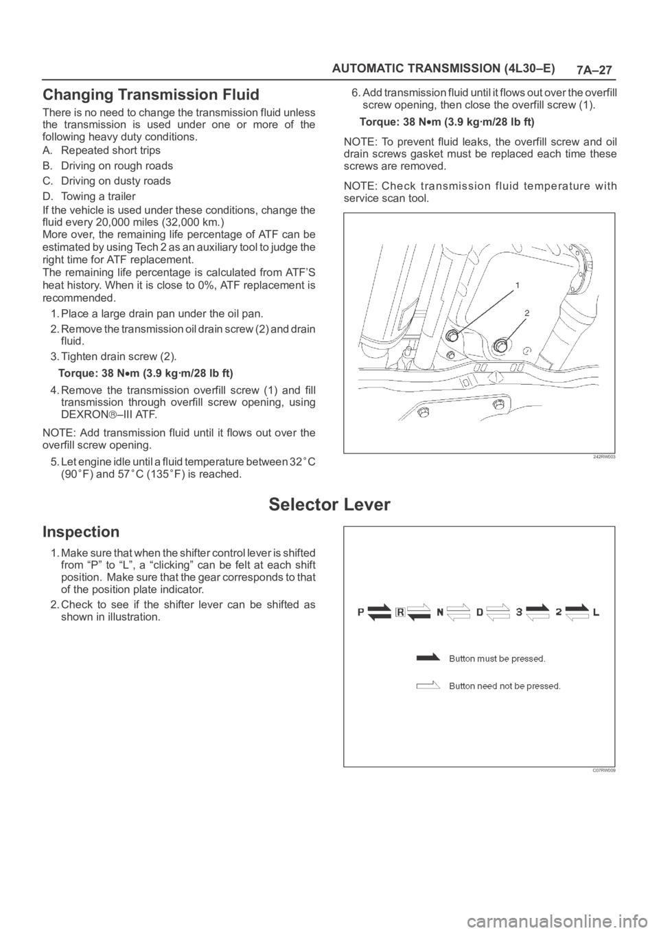
1. Place a large drain pan under the oil pan.
2. Remove the transmission oil drain screw (2) and drain
fluid.
3. Tighten drain screw (2).
Torque: 38 N
m (3.9 kgꞏm/28 lb ft)
4. Remove the transmission overfill screw (1) and fill
transmission through overfill screw opening, using
DEXRON
–III ATF.
NOTE: Add transmission fluid until it flows out over the
overfill screw opening.
5. Let engine idle until a fluid temperature between 32
C
(90
F) and 57C (135F) is reached.6. Add transmission fluid until it flows out over the overfill
screw opening, then close the overfill screw (1).
To r q u e : 3 8 N
m (3.9 kgꞏm/28 lb ft)
NOTE: To prevent fluid leaks, the overfill screw and oil
drain screws gasket must be replaced each time these
screws are removed.
NOTE: Check transmission fluid temperature with
service scan tool.
242RW003
Selector Lever
Inspection
1. Make sure that when the shifter control lever is shifted
from “P” to “L”, a “clicking” can be felt at each shift
position. Make sure that the gear corresponds to that
of the position plate indicator.
2. Check to see if the shifter lever can be shifted as
shown in illustration.
C07RW009
Page 2182 of 6000
7A–28
AUTOMATIC TRANSMISSION (4L30–E)
Removal
1. Disconnect battery ground cable.
2. Remove transfer control lever knob.
3. Remove front console.
Disconnect wiring harness connectors from front
console.
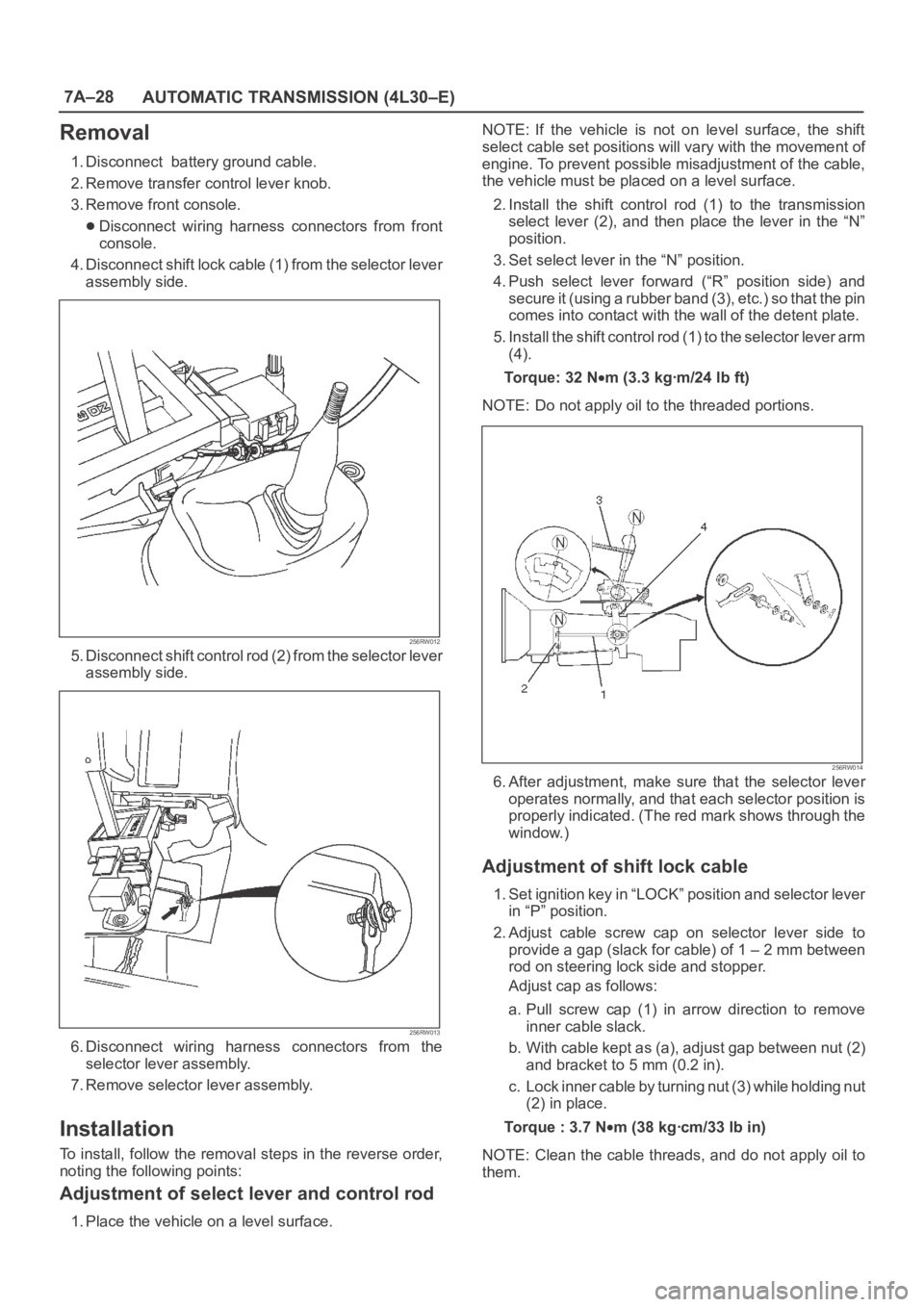
4. Disconnect shift lock cable (1) from the selector lever
assembly side.
256RW012
5. Disconnect shift control rod (2) from the selector lever
assembly side.
256RW013
6. Disconnect wiring harness connectors from the
selector lever assembly.
7. Remove selector lever assembly.
Installation
To install, follow the removal steps in the reverse order,
noting the following points:
Adjustment of select lever and control rod
1. Place the vehicle on a level surface.NOTE: If the vehicle is not on level surface, the shift
select cable set positions will vary with the movement of
engine. To prevent possible misadjustment of the cable,
the vehicle must be placed on a level surface.
2. Install the shift control rod (1) to the transmission
select lever (2), and then place the lever in the “N”
position.
3. Set select lever in the “N” position.
4. Push select lever forward (“R” position side) and
s e c u r e i t ( u s i n g a r u b b e r b a n d ( 3 ) , e t c . ) s o t h a t t h e p i n
comes into contact with the wall of the detent plate.
5. Install the shift control rod (1) to the selector lever arm
(4).
To r q u e : 3 2 N
m (3.3 kgꞏm/24 lb ft)
NOTE: Do not apply oil to the threaded portions.
256RW014
6. After adjustment, make sure that the selector lever
operates normally, and that each selector position is
properly indicated. (The red mark shows through the
window.)
Adjustment of shift lock cable
1. Set ignition key in “LOCK” position and selector lever
in “P” position.
2. Adjust cable screw cap on selector lever side to
provide a gap (slack for cable) of 1 – 2 mm between
rod on steering lock side and stopper.
Adjust cap as follows:
a. Pull screw cap (1) in arrow direction to remove
inner cable slack.
b. With cable kept as (a), adjust gap between nut (2)
and bracket to 5 mm (0.2 in).
c. Lock inner cable by turning nut (3) while holding nut
(2) in place.
Torque : 3.7 N
m (38 kgꞏcm/33 lb in)
NOTE: Clean the cable threads, and do not apply oil to
them.
Page 2183 of 6000
7A–29 AUTOMATIC TRANSMISSION (4L30–E)
256RW015
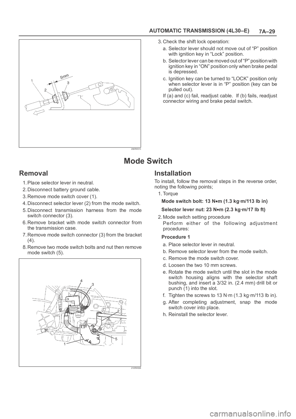
3. Check the shift lock operation:
a. Selector lever should not move out of “P” position
with ignition key in “Lock” position.
b. Selector lever can be moved out of “P” position with
ignition key in “ON” position only when brake pedal
is depressed.
c. Ignition key can be turned to “LOCK” position only
when selector lever is in “P” position (key can be
pulled out).
If (a) and (c) fail, readjust cable. If (b) fails, readjust
connector wiring and brake pedal switch.
Mode Switch
Removal
1. Place selector lever in neutral.
2. Disconnect battery ground cable.
3. Remove mode switch cover (1).
4. Disconnect selector lever (2) from the mode switch.
5. Disconnect transmission harness from the mode
switch connector (3).
6. Remove bracket with mode switch connector from
the transmission case.
7. Remove mode switch connector (3) from the bracket
(4).
8. Remove two mode switch bolts and nut then remove
mode switch (5).
210RW008
Installation
To install, follow the removal steps in the reverse order,
noting the following points;
1. Torque
Mode switch bolt: 13 N
m(1.3kgꞏm/113lbin)
Selector lever nut: 23 N
m (2.3 kgꞏm/17 lb ft)
2. Mode switch setting procedure
Perform either of the following adjustment
procedures:
Procedure 1
a. Place selector lever in neutral.
b. Remove selector lever from the mode switch.
c. Remove the mode switch cover.
d. Loosen the two 10 mm screws.
e. Rotate the mode switch until the slot in the mode
switch housing aligns with the selector shaft
bushing, and insert a 3/32 in. (2.4 mm) drill bit or
punch (1) into the slot.
f. Tighten the screws to 13 Nꞏm (1.3 kgꞏm/113 lb in).
g. After completing adjustment, snap the mode
switch cover into place.
h. Reinstall the selector lever.
Page 2184 of 6000
7A–30
AUTOMATIC TRANSMISSION (4L30–E)
249RW001
Procedure 2
a. Place selector lever in neutral.
b. Disconnect transmission harness connector from
mode switch connector.
c. Remove mode switch connector with bracket from
the transmission case.
d. Connect multimeter (resistance mode) to
terminals 1(E) and 4(H) on mode switch connector.
e. Loosen two mounting screws.
f. Rotate mode switch slightly in both directions to
determine the range (approx. 5 degrees) of
electrical contact.
g. Position mode switch in middle of contact range.
h. Tighten two mounting screws.
i. Remove multimeter and install mode switch
harness connector with bracket to the
transmission case.
j. Connect transmission harness connector to mode
switch connector.
F07RW003
Page 2185 of 6000
7A–31 AUTOMATIC TRANSMISSION (4L30–E)
Transmission (With Transfer Case)
Transmission And Associated Parts
240RW027
Legend
(1) Transfer Control Lever Knob
(2) Front Console
(3) Selector Lever Assembly
(4) Transfer Control Lever
(5) Transfer and Exhaust Protector
(6) Rear Propeller Shaft
(7) Front Propeller Shaft
(8) Harness Protector
(9) Rear Mount Nut(10) Third Crossmember
(11) Exhaust Pipe
(12) Transmission Oil Cooler Pipe
(13) Starter
(14) Transmission Harness Connector
(15) Under Cover
(16) Torque Converter Bolt
(17) Engine Transmission Bolt
(18) Transmission Assembly
Removal
NOTE: Before remove transmission and transfer
assembly from vehicle, change the tansfer mode to 2WD
using push button on dash panel.1. Remove engine hood.
2. Disconnect battery ground cable.
3. Remove transfer control lever knob (1) and
disconnect wiring harness connectors, then remove
front console (2).
Page 2186 of 6000
7A–32
AUTOMATIC TRANSMISSION (4L30–E)
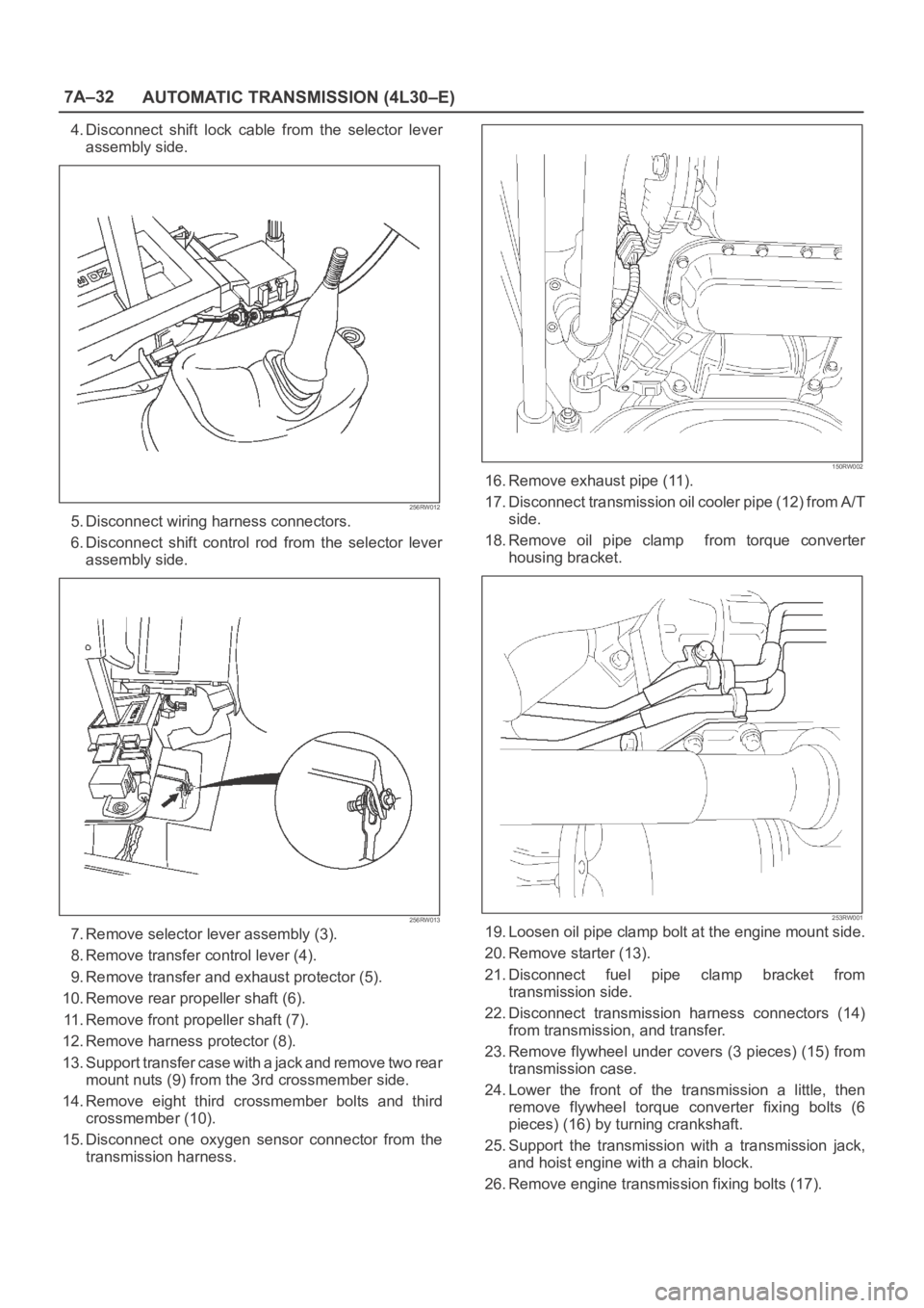
4. Disconnect shift lock cable from the selector lever
assembly side.
256RW012
5. Disconnect wiring harness connectors.
6. Disconnect shift control rod from the selector lever
assembly side.
256RW013
7. Remove selector lever assembly (3).
8. Remove transfer control lever (4).
9. Remove transfer and exhaust protector (5).
10. Remove rear propeller shaft (6).
11. Remove front propeller shaft (7).
12. Remove harness protector (8).
13. Support transfer case with a jack and remove two rear
mount nuts (9) from the 3rd crossmember side.
14. Remove eight third crossmember bolts and third
crossmember (10).
15. Disconnect one oxygen sensor connector from the
transmission harness.
150RW002
16. Remove exhaust pipe (11).
17. Disconnect transmission oil cooler pipe (12) from A/T
side.
18. Remove oil pipe clamp from torque converter
housing bracket.
253RW001
19. Loosen oil pipe clamp bolt at the engine mount side.
20. Remove starter (13).
21. Disconnect fuel pipe clamp bracket from
transmission side.
22. Disconnect transmission harness connectors (14)
from transmission, and transfer.
23. Remove flywheel under covers (3 pieces) (15) from
transmission case.
24. Lower the front of the transmission a little, then
remove flywheel torque converter fixing bolts (6
pieces) (16) by turning crankshaft.
25. Support the transmission with a transmission jack,
and hoist engine with a chain block.
26. Remove engine transmission fixing bolts (17).