Page 3973 of 6000

4A2A–4
DIFFERENTIAL (REAR 220mm)
Axle Housing
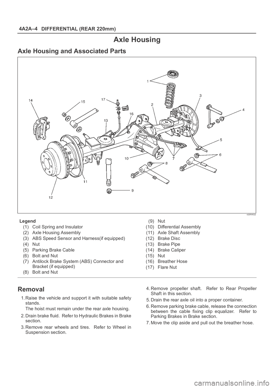
Axle Housing and Associated Parts
420RW022
Legend
(1) Coil Spring and Insulator
(2) Axle Housing Assembly
(3) ABS Speed Sensor and Harness(if equipped)
(4) Nut
(5) Parking Brake Cable
(6) Bolt and Nut
(7) Antilock Brake System (ABS) Connector and
Bracket (if equipped)
(8) Bolt and Nut(9) Nut
(10) Differential Assembly
(11) Axle Shaft Assembly
(12) Brake Disc
(13) Brake Pipe
(14) Brake Caliper
(15) Nut
(16) Breather Hose
(17) Flare Nut
Removal
1. Raise the vehicle and support it with suitable safety
stands.
The hoist must remain under the rear axle housing.
2. Drain brake fluid. Refer to Hydraulic Brakes in Brake
section.
3. Remove rear wheels and tires. Refer to Wheel in
Suspension section.4. Remove propeller shaft. Refer to Rear Propeller
Shaft in this section.
5. Drain the rear axle oil into a proper container.
6. Remove parking brake cable, release the connection
between the cable fixing clip equalizer. Refer to
Parking Brakes in Brake section.
7. Move the clip aside and pull out the breather hose.
Page 3974 of 6000

DIFFERENTIAL (REAR 220mm)
4A2A–5
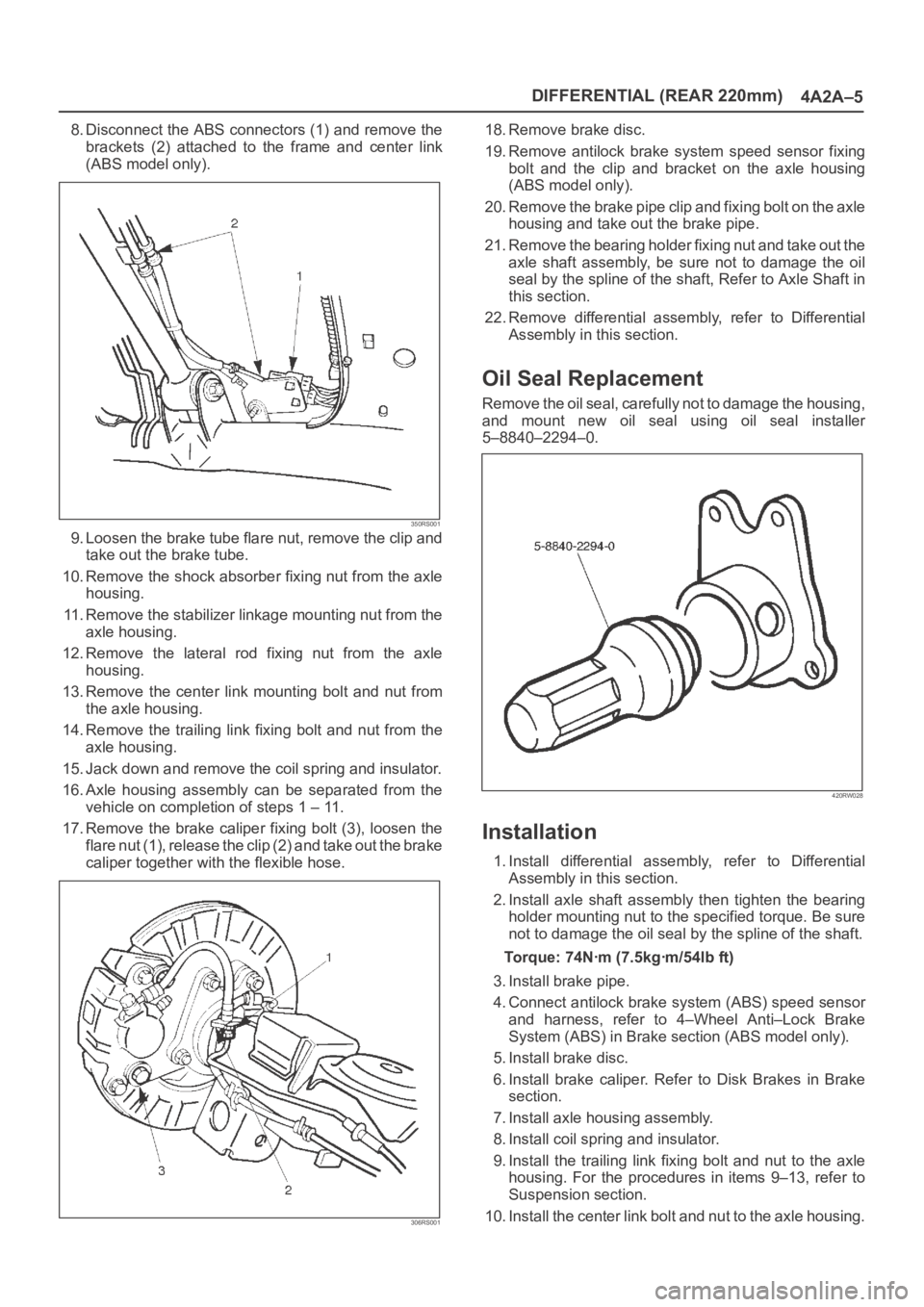
8. Disconnect the ABS connectors (1) and remove the
brackets (2) attached to the frame and center link
(ABS model only).
350RS001
9. Loosen the brake tube flare nut, remove the clip and
take out the brake tube.
10. Remove the shock absorber fixing nut from the axle
housing.
11. Remove the stabilizer linkage mounting nut from the
axle housing.
12. Remove the lateral rod fixing nut from the axle
housing.
13. Remove the center link mounting bolt and nut from
the axle housing.
14. Remove the trailing link fixing bolt and nut from the
axle housing.
15. Jack down and remove the coil spring and insulator.
16. Axle housing assembly can be separated from the
vehicle on completion of steps 1 – 11.
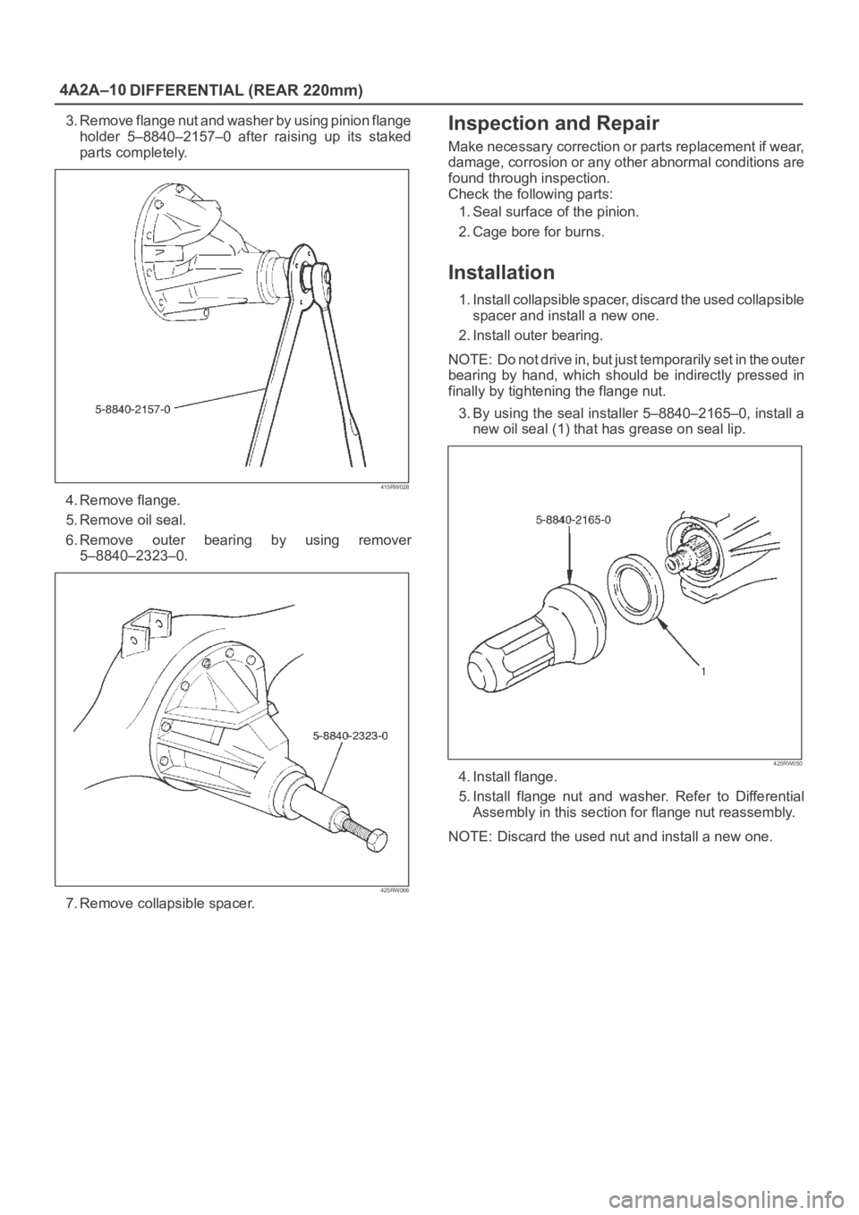
17. Remove the brake caliper fixing bolt (3), loosen the
flare nut (1), release the clip (2) and take out the brake
caliper together with the flexible hose.
306RS001
18. Remove brake disc.
19. Remove antilock brake system speed sensor fixing
bolt and the clip and bracket on the axle housing
(ABS model only).
20. Remove the brake pipe clip and fixing bolt on the axle
housing and take out the brake pipe.
21. Remove the bearing holder fixing nut and take out the
axle shaft assembly, be sure not to damage the oil
seal by the spline of the shaft, Refer to Axle Shaft in
this section.
22. Remove differential assembly, refer to Differential
Assembly in this section.
Oil Seal Replacement
Remove the oil seal, carefully not to damage the housing,
and mount new oil seal using oil seal installer
5–8840–2294–0.
420RW028
Installation
1. Install differential assembly, refer to Differential
Assembly in this section.
2. Install axle shaft assembly then tighten the bearing
holder mounting nut to the specified torque. Be sure
not to damage the oil seal by the spline of the shaft.
Torque: 74Nꞏm (7.5kgꞏm/54lb ft)
3. Install brake pipe.
4. Connect antilock brake system (ABS) speed sensor
and harness, refer to 4–Wheel Anti–Lock Brake
System (ABS) in Brake section (ABS model only).
5. Install brake disc.
6. Install brake caliper. Refer to Disk Brakes in Brake
section.
7. Install axle housing assembly.
8. Install coil spring and insulator.
9. Install the trailing link fixing bolt and nut to the axle
housing. For the procedures in items 9–13, refer to
Suspension section.
10. Install the center link bolt and nut to the axle housing.
Page 3976 of 6000
DIFFERENTIAL (REAR 220mm)
4A2A–7
7.Remove the parking brake cable mounting
bolts(Behind the back plate)(1).
311RS001
8. Remove the bearing holder mounting nuts.
9. Remove axle shaft assembly.
NOTE: Be sure not to damage the oil seal.
10. Remove snap ring.
11. Using a bearing remover 5–8840–2295–0 and press,
remove retainer together with the bearing holder.
420RY00012
12. Remove bearing.
13. Remove bearing holder.
14. Remove back plate.15. Remove the wheel pins using a remover
5–8840–0029–0.
420RY00011
Inspection and Repair
Make necessary correction or parts replacement if wear,
corrosion or any other abnormal conditions are found
through inspection.
Visual Check:
Check the following parts for wear, damage, noise or any
other abnormal conditions:
1. Axle shaft
2. Bearing
When checking the axle shaft, pay special attention to the
splined portions and replace the shaft if distortion or step
wear is noticeable. Correct slight step wear with a grinder.
420RS008
Page 3977 of 6000
4A2A–8
DIFFERENTIAL (REAR 220mm)
Axle Shaft Run–out
Limit: 1.0 mm (0.039 in)
420RS009
Axle Shaft Flange Run–out
Limit: 0.08 mm (0.003 in)
420RS010
Oil Seal Replacement
Remove the oil seal carefully not to damage the bearing
holder bore .
When installing, use oil seal installer 5–8840–2310–0.
420RY00009
Installation
1. Install wheel pin.
2. Install back plate.
3. Install bearing holder.
4. Install bearing.
5. Install retainer by using a bearing installer
5–8840–2296–0, press fit together with the bearing.
420RY00010
Page 3978 of 6000
DIFFERENTIAL (REAR 220mm)
4A2A–9
6. Install snap ring.
7. Install axle shaft assembly.
NOTE: Be sure not to damage the oil seal.
8. Tighten the bearing holder mounting nut to the
specified torque.
Torque: 74Nꞏm (54 Ib ft)
9. Fix the parking brake cable mounting bolt (Behind the
back plate).10. Install parking brake assembly, refer to Parking
Brakes in Brake section.
11. Install antilock brake system sensor.
12. Install brake disc.
13. Install brake caliper, refer to Disk Brakes in Brake
section.
Pinion Oil Seal
Pinion Oil Seal and Associated Parts
425RW054
Legend
(1) Flange Nut and Washer
(2) Flange(3) Oil Seal
(4) Outer Bearing
(5) Collapsible Spacer
Removal
1.Remove the rear propeller shaft. Refer to Rear
Propeller Shaft in this section.
2. Drain the rear axle oil.
Page 3979 of 6000

4A2A–10
DIFFERENTIAL (REAR 220mm)
3. Remove flange nut and washer by using pinion flange
holder 5–8840–2157–0 after raising up its staked
parts completely.
415RW028
4. Remove flange.
5. Remove oil seal.
6. Remove outer bearing by using remover
5–8840–2323–0.
425RW066
7. Remove collapsible spacer.
Inspection and Repair
Make necessary correction or parts replacement if wear,
damage, corrosion or any other abnormal conditions are
found through inspection.
Check the following parts:
1. Seal surface of the pinion.
2. Cage bore for burns.
Installation
1. Install collapsible spacer, discard the used collapsible
spacer and install a new one.
2. Install outer bearing.
NOTE: Do not drive in, but just temporarily set in the outer
bearing by hand, which should be indirectly pressed in
finally by tightening the flange nut.
3. By using the seal installer 5–8840–2165–0, install a
new oil seal (1) that has grease on seal lip.
425RW050
4. Install flange.
5. Install flange nut and washer. Refer to Differential
Assembly in this section for flange nut reassembly.
NOTE: Discard the used nut and install a new one.
Page 3980 of 6000
DIFFERENTIAL (REAR 220mm)
4A2A–11
Differential Assembly
Differential Assembly and Associated Parts
425RW055
Legend
(1) Bolt and Nut
(2) Axle Shaft Assembly(3) Parking Brake Cable
(4) Differential Assembly
(5) Nut
Removal
1. Jack up and support the frame with stands.
2. Remove the wheel and tire. Refer to Wheel in
Steering section.
3. Drain the differential oil.
4. Remove the propeller shaft. Refer to Rear Propeller
Shaft in this section.
5. Remove the ABS speed sensor(ABS model only).
Refer to 4–Wheel Anti–lock Brake System (ABS) in
Brake section.6. Remove the parking brake cable fastening clip and
disconnect the equalizer section. Refer to Parking
Brakes in Brake section.
7. Remove the bearing holder fixing nuts.
8. Remove axle shaft assembly, be sure not to damage
the oil seal by axle shaft.
9. Remove differential carrier mounting bolts and nuts.
10. Remove differential assembly.
Page 3981 of 6000
4A2A–12
DIFFERENTIAL (REAR 220mm)
Installation
1. Clean the contact surfaces of the axle and differential
carrier. As shown in the drawing, apply Three Bond
TB1215 or equivalent then install differential
assembly.
425RS006
2. Install bolt and nut. Tighten the differential carrier
mounting bolts and nuts to the specified torque.
Torque:Nuts 44Nꞏm (4.5kgꞏm/33lb ft)
Bolts 64Nꞏm (6.5kgꞏm/47lb ft)
3. Install axle shaft assembly. Be sure not to damage
the oil seal by axle shaft.
4. Install nut, refer to Axle Shaft in this section.
5. Install parking brake cable, refer to Parking Brakes in
Brake section.
NOTE: After completing the assembling work, fill the
prescribed gear oil to the filler hole.
Lubricant capacity: 1.8 liter (1.6 Imp qt/1.9US
qt)
6. Tighten the oil filler plug to the specified torque.
Torque: 78Nꞏm (8.0kgꞏm/58lb ft)