Page 4040 of 6000

DIFFERENTIAL (REAR 244mm)
4A2B–33
3. After measuring dimensions of each of the above
sections, proceed with the adjustment in the following
manner:
Adjust the clearance to satisfy the equation below.
{(F – B) + G – H}=0.05 – 0.20 mm
Also, select the thrust washers so that the
dimensional difference between the back surfaces of
the left and right pressure rings to the thrust washers
is 0.05mm or less.
Thickness : 1.5mm (0.059 in)
1.6 mm(0.063 in)
1.7 mm(0.067 in)
NOTE: When assembling the parts, apply recommended
gear oil sufficiently to each of the parts, especially, to the
contact surfaces and sliding surfaces.
1. Install Differential cage B.
2. Install Thrust washer.
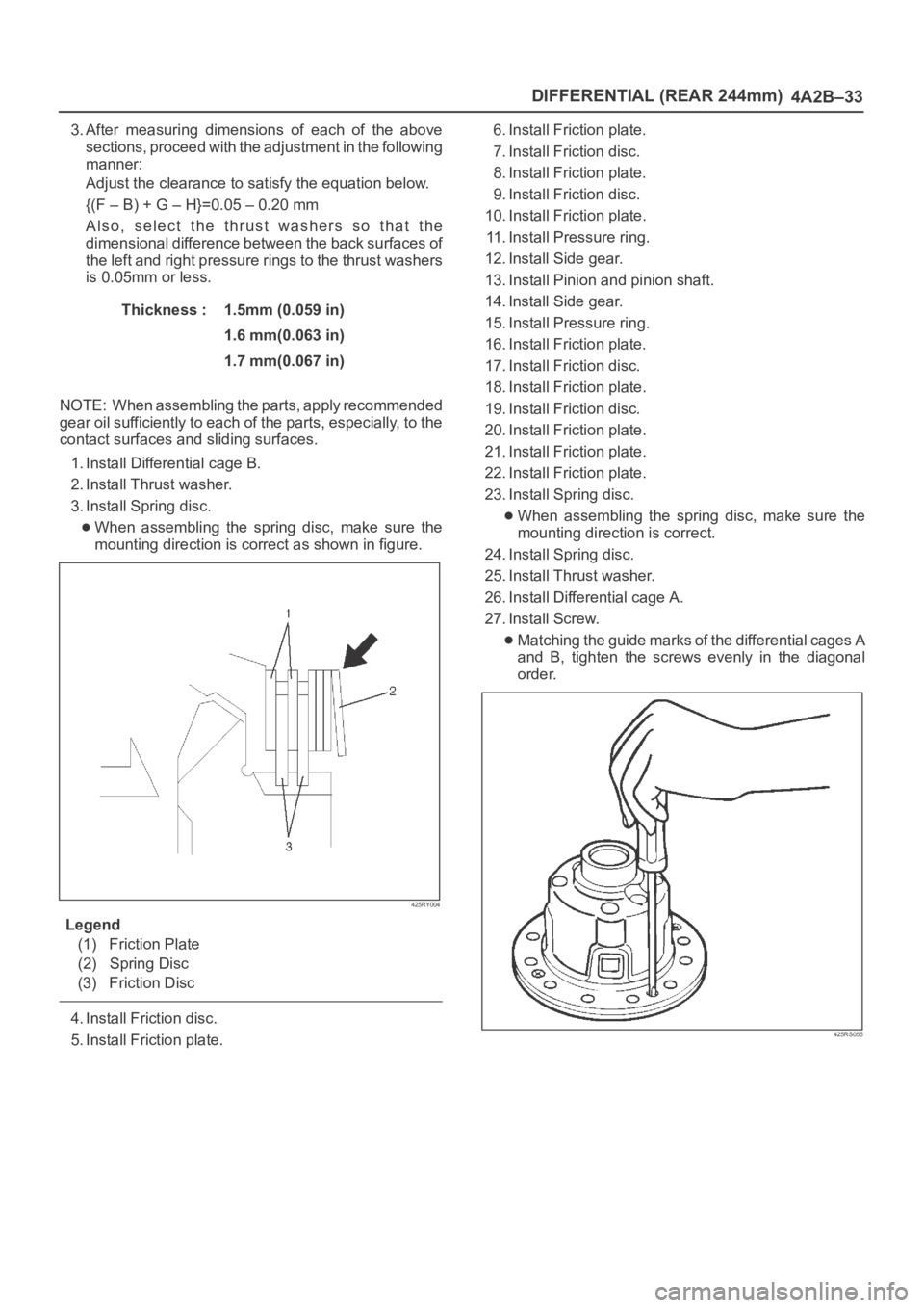
3. Install Spring disc.
When assembling the spring disc, make sure the
mounting direction is correct as shown in figure.
425RY004
Legend
(1) Friction Plate
(2) Spring Disc
(3) Friction Disc
4. Install Friction disc.
5. Install Friction plate.6. Install Friction plate.
7. Install Friction disc.
8. Install Friction plate.
9. Install Friction disc.
10. Install Friction plate.
11. Install Pressure ring.
12. Install Side gear.
13. Install Pinion and pinion shaft.
14. Install Side gear.
15. Install Pressure ring.
16. Install Friction plate.
17. Install Friction disc.
18. Install Friction plate.
19. Install Friction disc.
20. Install Friction plate.
21. Install Friction plate.
22. Install Friction plate.
23. Install Spring disc.
When assembling the spring disc, make sure the
mounting direction is correct.
24. Install Spring disc.
25. Install Thrust washer.
26. Install Differential cage A.
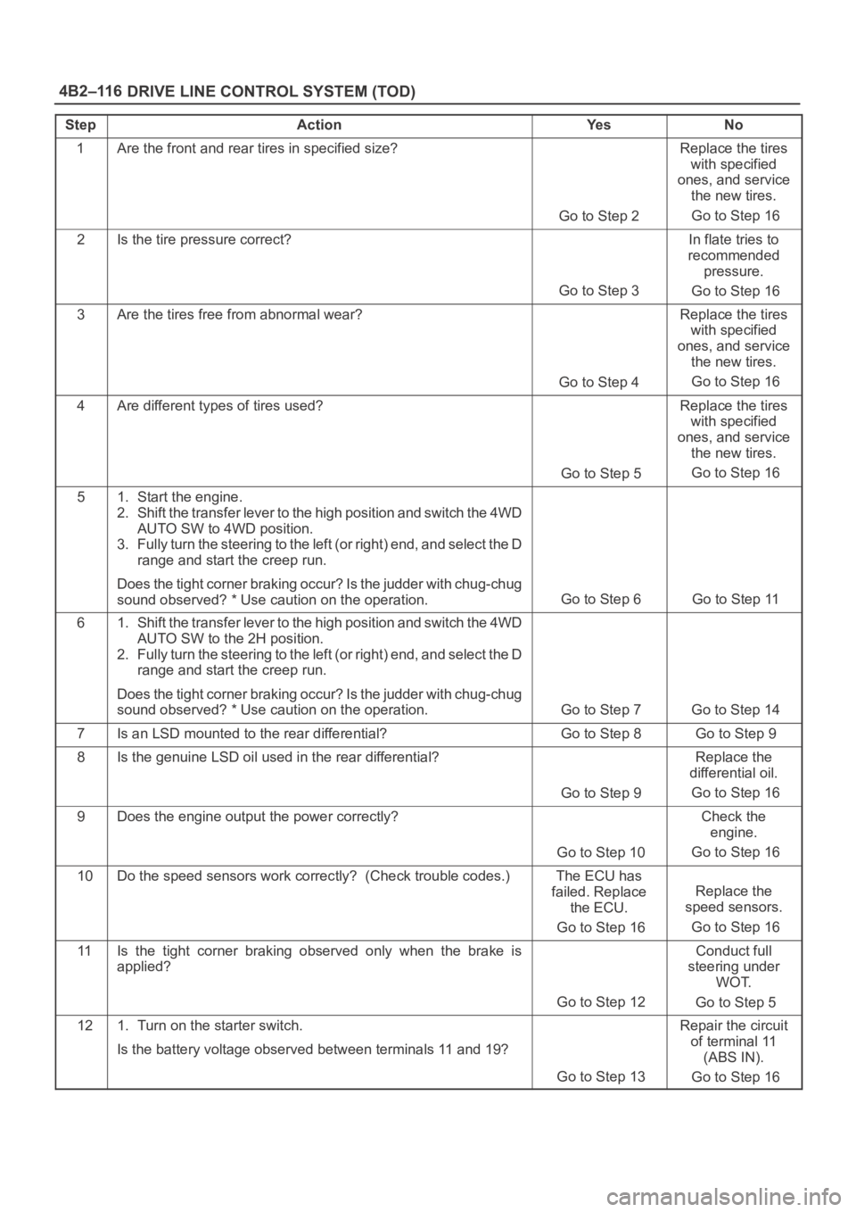
27. Install Screw.
Matching the guide marks of the differential cages A
and B, tighten the screws evenly in the diagonal
order.
425RS055
Page 4044 of 6000
DIFFERENTIAL (REAR 244mm)
4A2B–37
Special Tools
ILLUSTRATIONTOOL NO.
TOOL NAME
5–8840–2294–0
(J–39210)
Installer; Axle shaft inner
seal
5–8840–0133–0
(J–8614–01)
Pinion flange holder
5–8840–2165–0
(J–37263)
Installer; Pinion oil seal
5–8840–2029–0
(J–42832)
Holding fixture
5–8840–0003–0
(J–3289–20)
Holding fixture base
5–8840–2587–0
(J–42379)
Remover; Bearing
ILLUSTRATIONTOOL NO.
TOOL NAME
5–8840–2576–0
(J–8107–3)
Adapter; Side bearing
plug
5–8840–2689–0
(J–44461)
Installer; Outer bearing
outer race
5–8840–0007–0
(J–8092)
Grip
5–8840–2690–0
(J–44462)
Installer; Inner bearing
outer race
5–8840–2681–0
(J–42824)
Pilot;Outer
5–8840–0127–0
(J–21777–43)
Nut & Bolt
Page 4199 of 6000

DRIVE LINE CONTROL SYSTEM (TOD) 4B2–116
StepActionYe sNo
1Are the front and rear tires in specified size?
Go to Step 2
Replace the tires
with specified
ones, and service
the new tires.
Go to Step 16
2Is the tire pressure correct?
Go to Step 3
In flate tries to
recommended
pressure.
Go to Step 16
3Are the tires free from abnormal wear?
Go to Step 4
Replace the tires
with specified
ones, and service
the new tires.
Go to Step 16
4Are different types of tires used?
Go to Step 5
Replace the tires
with specified
ones, and service
the new tires.
Go to Step 16
51. Start the engine.
2. Shift the transfer lever to the high position and switch the 4WD
AUTO SW to 4WD position.
3. Fully turn the steering to the left (or right) end, and select the D
range and start the creep run.
Does the tight corner braking occur? Is the judder with chug-chug
sound observed? * Use caution on the operation.
Go to Step 6 Go to Step 11
61. Shift the transfer lever to the high position and switch the 4WD
AUTO SW to the 2H position.
2. Fully turn the steering to the left (or right) end, and select the D
range and start the creep run.
Does the tight corner braking occur? Is the judder with chug-chug
sound observed? * Use caution on the operation.
Go to Step 7 Go to Step 14
7Is an LSD mounted to the rear differential? Go to Step 8 Go to Step 9
8Is the genuine LSD oil used in the rear differential?
Go to Step 9
Replace the
differential oil.
Go to Step 16
9Does the engine output the power correctly?
Go to Step 10
Check the
engine.
Go to Step 16
10Do the speed sensors work correctly? (Check trouble codes.)The ECU has
failed. Replace
the ECU.
Go to Step 16
Replace the
speed sensors.
Go to Step 16
11Is the tight corner braking observed only when the brake is
applied?
Go to Step 12
Conduct full
steering under
WOT.
Go to Step 5
121. Turn on the starter switch.
Is the battery voltage observed between terminals 11 and 19?
Go to Step 13
Repair the circuit
of terminal 11
(ABS IN).
Go to Step 16
Page 4209 of 6000

4C–3 DRIVE SHAFT SYSTEM
Diagnosis
ConditionPossible causeCorrection
Oil Leak At Front AxleWorn or defective oil seal.Replace the oil seal.
Front axle housing cracked.Repair or replace.
Oil Leak At Pinion ShaftToo much gear oil.Correct the oil level.
Oil seal worn or defective.Replace the oil seal.
Pinion flange loose or damaged.Tighten or replace.
Noises In Front Axle Drive Shaft
JointBroken or worn drive shaft joints and
bellows (BJ and DOJ).Replace the drive shaft joints and
bellows.
“Clank” When Accelerating From
“Coast”Loose drive shaft joint to output shaft
bolts.Tighten.
Damaged inner drive shaft joint.Replace.
Shudder or Vibration During
Acceleration
Excessive drive shaft joint angle.Repair.
AccelerationWorn or damaged drive shaft joints.Replace.
Sticking spider assembly (inner drive
shaft joint).Lubricate or replace.
Sticking joint assembly (outer drive
shaft joint).Lubricate or replace.
Vibration At Highway SpeedsOut of balance or out of round tires.Balance or replace.
Front end out of alignment.Align.
Noises in Front AxleInsufficient gear oil.Replenish the gear oil.
Wrong or poor grade gear oil.Replace the gear oil.
Drive pinion to ring gear backlash
incorrect.Adjust the backlash.
Worn or chipped ring gear, pinion
gear or side gear.Replace the ring gear, pinion gear or
side gear.
Pinion shaft bearing worn.Replace the pinion shaft bearing.
Wheel bearing worn.Replace the wheel bearing.
Differential bearing loose or worn.Tighten or replace.
Wanders and PullsWheel bearing preload too tight.Adjust the wheel bearing preload.
Incorrect front alignment.Adjust the front alignment.
Steering linkage loose or worn.Tighten or replace.
Steering gear out of adjustment.Adjust or replace the steering gear.
Tire worn or improperly inflated.Adjust the inflation or replace.
Front or rear suspension parts loose
or broken.Tighten or replace.
Front Wheel ShimmyWheel bearing worn or improperly
adjusted.Adjust or replace.
Incorrect front alignment.Adjust the front alignment.
Worn ball joint or bush.Replace the ball joint or bush.
Steering linkage loose or worn.Tighten or replace.
Steering gear out of adjustment.Tighten or replace.
Tire worn or improperly inflated.Replace or adjust the inflation.
Shock absorber worn.Replace the shock absorber.
Page 4229 of 6000
4C–23 DRIVE SHAFT SYSTEM
Front Axle Drive Shaft
Front Axle Drive Shaft and Associated Parts
This illustration is based on the model equipped with shift on the fly system.
412RW003
Legend
(1) Axle Case and Differential
(2) DOJ Case Assembly
(3) Snap Ring
(4) Bearing
(5) Snap Ring
(6) Oil Seal
(7) Bracket
(8) DOJ Case
(9) Circlip
(10) Bolt
(11) Drive Shaft Joint Assembly
(12) Snap Ring(13) Spacer
(14) Ball
(15) Snap Ring
(16) Ball Retainer
(17) Ball Guide
(18) Band
(19) Bellows
(20) Band
(21) Band
(22) Bellows
(23) Band
(24) BJ Shaft
(25) Dust Seal
Page 4239 of 6000
4C–33 DRIVE SHAFT SYSTEM
412RS037
Reassembly
1. Install the new oil seal which has been immersed in
differential gear oil, by using an oil seal installer
5–8840–2407–0 and grip 5–8840–0007–0.
412RS043
2. Force a new needle bearing into inner shaft by using a
installer 5–8840–2408–0 and grip 5–8840–0007–0.
412RS051
3. Place a new snap ring(internal) in inner shaft.
Force a new inner shaft bearing into the inner shaft by
using a installer 5–8840–2197–0 and press.
412RS044
4. Install snap ring(external).
NOTE: Be careful not to damage the inner shaft.
5. Clean the housing contact surface of the front axle
case and insert inner shaft assembly into the front
axle case.
Page 4240 of 6000

4C–34
DRIVE SHAFT SYSTEM
NOTE: Be careful not to damage seal.
6. Install snap ring (internal) in the groove of front axle
case.
NOTE: Be sure to install the snap ring properly.
412RW017
7. Apply differential gear oil to clutch gear, then install
clutch gear.
8. Apply differential gear oil to sleeve, then install
sleeve.
9. Clean contact surface with the front axle and actuator
mounting surface. Apply liquid gasket to the contact
surface on the front axle case, then install in the
housing.
412RW023
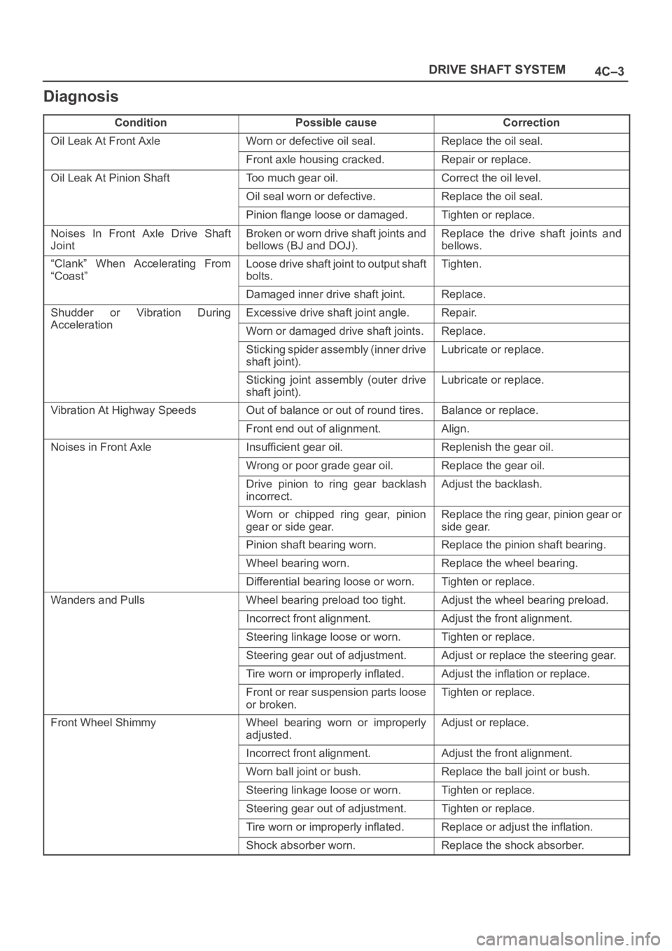
10. Tighten bolts to specified torque.
Torque: 116Nꞏm (11.8 kgꞏm/85 lb ft)11. Clean the actuator contact surface with the housing
then Install and tighten shift position switch to
specified torque.
Torque: 39Nꞏm (4.0 kgꞏm/29 lb ft)
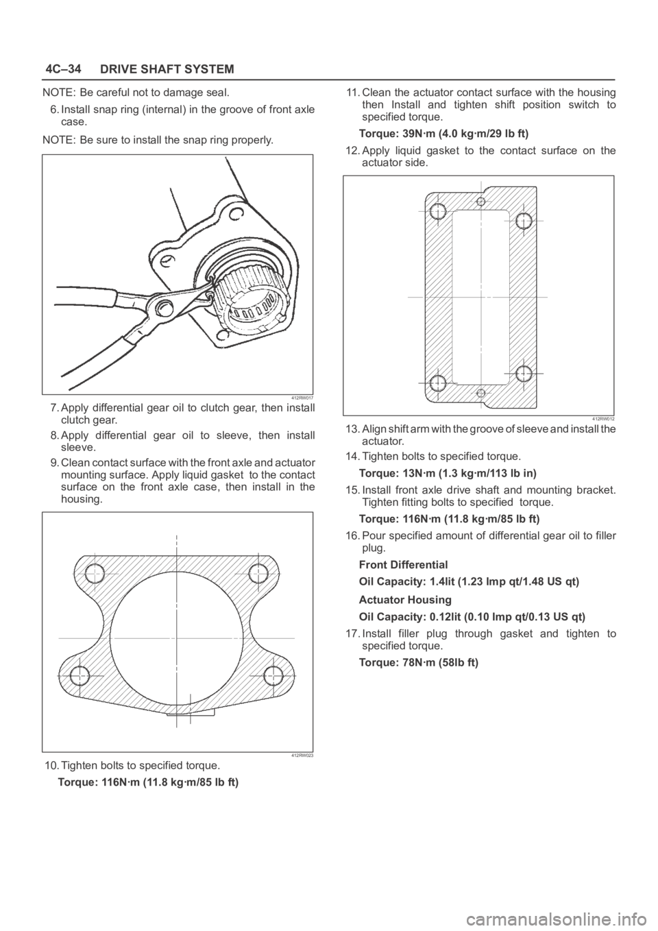
12. Apply liquid gasket to the contact surface on the
actuator side.
412RW012
13. Align shift arm with the groove of sleeve and install the
actuator.
14. Tighten bolts to specified torque.
Torque: 13Nꞏm (1.3 kgꞏm/113 lb in)
15. Install front axle drive shaft and mounting bracket.
Tighten fitting bolts to specified torque.
Torque: 116Nꞏm (11.8 kgꞏm/85 lb ft)
16. Pour specified amount of differential gear oil to filler
plug.
Front Differential
Oil Capacity: 1.4lit (1.23 Imp qt/1.48 US qt)
Actuator Housing
Oil Capacity: 0.12lit (0.10 Imp qt/0.13 US qt)
17. Install filler plug through gasket and tighten to
specified torque.
To r q u e : 7 8 N ꞏm ( 5 8 l b f t )
Page 4241 of 6000
4C–35 DRIVE SHAFT SYSTEM
Main Data and Specifications
General Specifications
Front drive axle oil capacity1.4 liter (1.23 Imp qt/1.48 US qt)(Differential)
0.12 liter (0.10 Imp qt/0.13 US qt)(Actuator Housing:Shift on the fly)
Type of lubricantGL–5 (Multi grade type) Refer to chart in General Information
Axle shaft typeConstant velocity joint(Birfield joint type and double offset joint)
Torque Specifications
E04RW020