Page 3982 of 6000
DIFFERENTIAL (REAR 220mm)
4A2A–13
Disassembled View
415RW035
Legend
(1) Bolt
(2) Bearing Cap
(3) Side Bearing
(4) Adjust Shim
(5) Diff Cage Assembly
(6) Side Bearing Outer Race
(7) Pinion Gear
(8) Adjust Shim
(9) Inner Bearing (10) Inner Bearing Outer Race
(11) Collapsible Spacer
(12) Differential Carrier
(13) Outer Bearing Outer Race
(14) Outer Bearing
(15) Oil Seal
(16) Dust Cover
(17) Flange
(18) Flange Nut
Page 3984 of 6000
DIFFERENTIAL (REAR 220mm)
4A2A–15
11. Remove the drive pinion assembly using a soft metal
rod and a hammer.
425RW056
12. Remove collapsible spacer.
13. Remove the inner bearing using a separator
5–8840–2197–0 and a press.
415RW039
14. Remove adjust shim.
15. Remove inner bearing outer race.
16. Remove oil seal.
17. Remove outer bearing.18. Remove the inner bearing outer race (1) and the outer
bearing outer race (2) by using a brass bar and a
hammer.
425RS014
425RS015
Page 3985 of 6000
4A2A–16
DIFFERENTIAL (REAR 220mm)
Reassembly
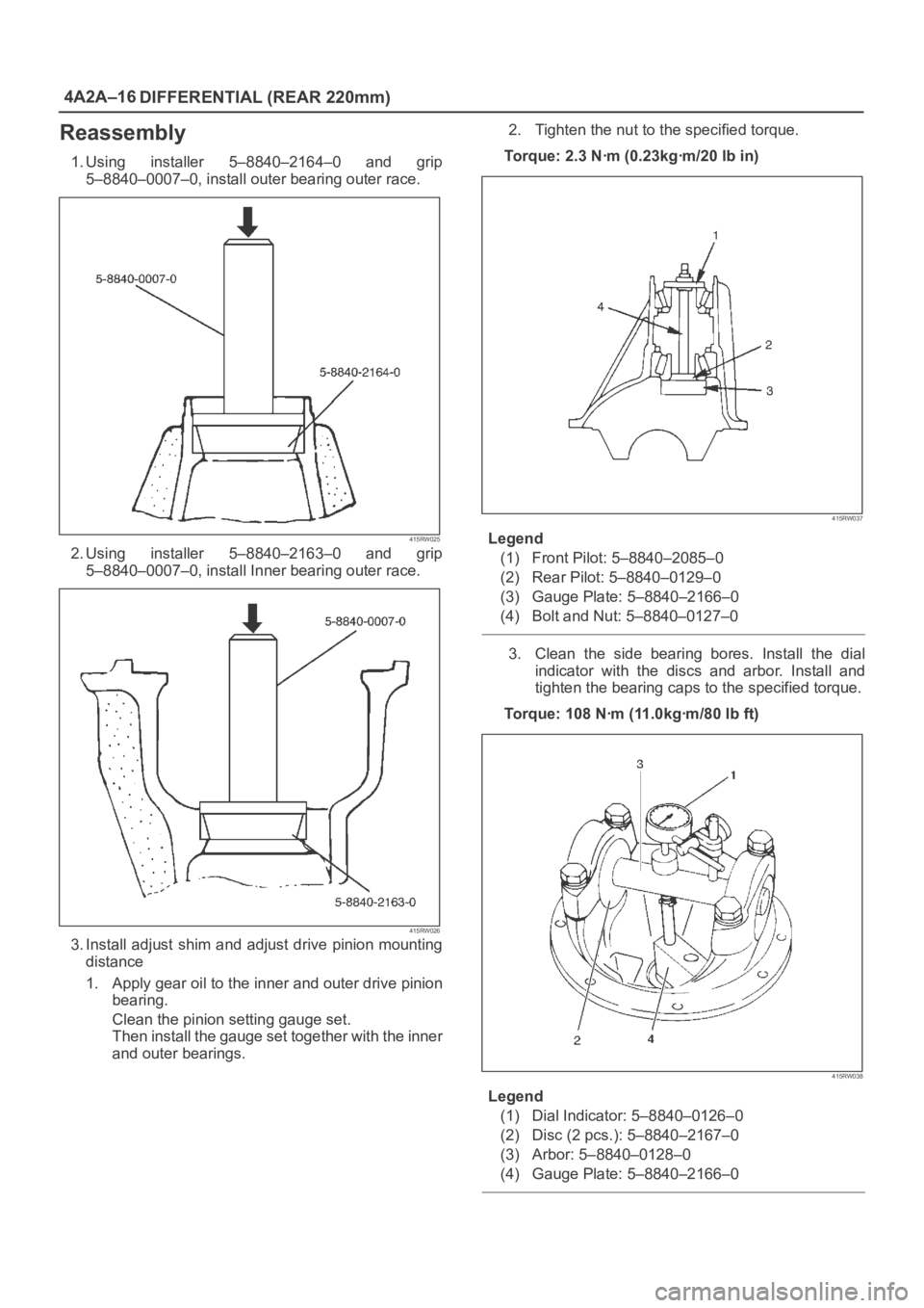
1. Using installer 5–8840–2164–0 and grip
5–8840–0007–0, install outer bearing outer race.
415RW025
2. Using installer 5–8840–2163–0 and grip
5–8840–0007–0, install Inner bearing outer race.
415RW026
3. Install adjust shim and adjust drive pinion mounting
distance
1. Apply gear oil to the inner and outer drive pinion
bearing.
Clean the pinion setting gauge set.
Then install the gauge set together with the inner
and outer bearings.2. Tighten the nut to the specified torque.
Torque: 2.3 Nꞏm (0.23kgꞏm/20 lb in)
415RW037
Legend
(1) Front Pilot: 5–8840–2085–0
(2) Rear Pilot: 5–8840–0129–0
(3) Gauge Plate: 5–8840–2166–0
(4) Bolt and Nut: 5–8840–0127–0
3. Clean the side bearing bores. Install the dial
indicator with the discs and arbor. Install and
tighten the bearing caps to the specified torque.
Torque: 108 Nꞏm (11.0kgꞏm/80 lb ft)
415RW038
Legend
(1) Dial Indicator: 5–8840–0126–0
(2) Disc (2 pcs.): 5–8840–2167–0
(3) Arbor: 5–8840–0128–0
(4) Gauge Plate: 5–8840–2166–0
Page 3988 of 6000
DIFFERENTIAL (REAR 220mm)
4A2A–19
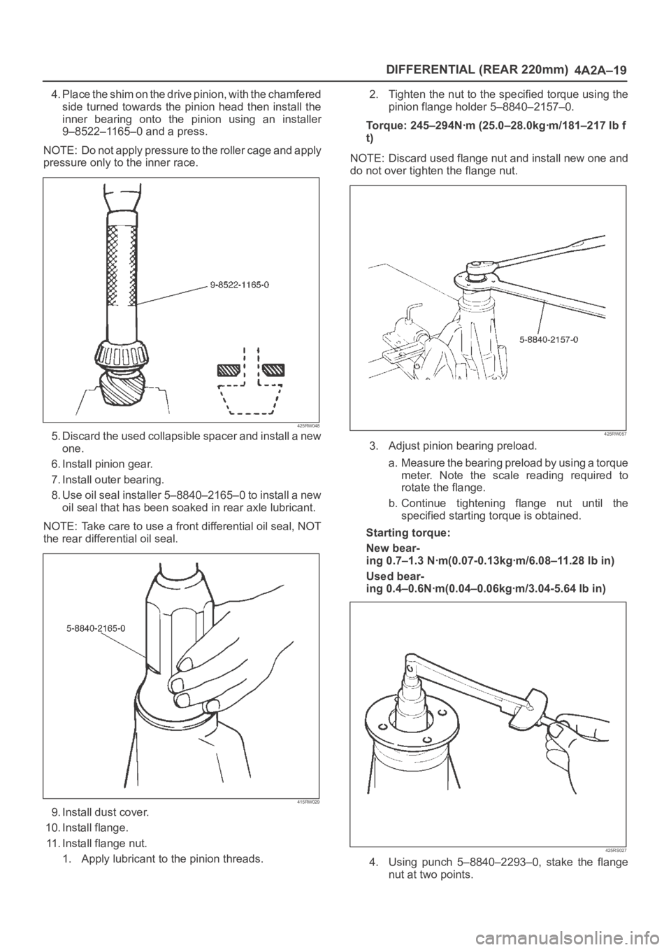
4. Place the shim on the drive pinion, with the chamfered
side turned towards the pinion head then install the
inner bearing onto the pinion using an installer
9–8522–1165–0 and a press.
NOTE: Do not apply pressure to the roller cage and apply
pressure only to the inner race.
425RW048
5. Discard the used collapsible spacer and install a new
one.
6. Install pinion gear.
7. Install outer bearing.
8. Use oil seal installer 5–8840–2165–0 to install a new
oil seal that has been soaked in rear axle lubricant.
NOTE: Take care to use a front differential oil seal, NOT
the rear differential oil seal.
415RW029
9. Install dust cover.
10. Install flange.
11. Install flange nut.
1. Apply lubricant to the pinion threads.2. Tighten the nut to the specified torque using the
pinion flange holder 5–8840–2157–0.
Torque: 245–294Nꞏm (25.0–28.0kgꞏm/181–217 lb f
t)
NOTE: Discard used flange nut and install new one and
do not over tighten the flange nut.
425RW057
3. Adjust pinion bearing preload.
a. Measure the bearing preload by using a torque
meter. Note the scale reading required to
rotate the flange.
b. Continue tightening flange nut until the
specified starting torque is obtained.
Starting torque:
New bear-
ing 0.7–1.3 Nꞏm(0.07-0.13kgꞏm/6.08–11.28 lb in)
Used bear-
ing 0.4–0.6Nꞏm(0.04–0.06kgꞏm/3.04-5.64 Ib in)
425RS027
4. Using punch 5–8840–2293–0, stake the flange
nut at two points.
Page 3994 of 6000
DIFFERENTIAL (REAR 220mm)
4A2A–25
4. Remove the cross pin, using a soft metal rod and a
hammer.
425RS043
5. Remove pinion gear.
6. Remove side gear.
7. Remove thrust washer.
Inspection and Repair
Make necessary correction or parts replacement if wear,
damage, corrosion or any other abnormal conditions are
found through inspection.
Check the following parts:
1. Ring gear, pinion gear
2. Bearing
3. Side gear, pinion gear, cross pin
4. Differential cage, carrier
5. Thrust washer
6. Oil seal
Ring gear replacement:
1. The ring gear should always be replaced with the
drive pinion as a set.
2. Clean the ring gear threaded holes to remove the
locking agent.
3. When installing the ring gear, apply LOCTITE 271 or
equivalent to all the threaded area and half of the
unthreaded area of the bolt.
4. Discard used bolts and install new ones.
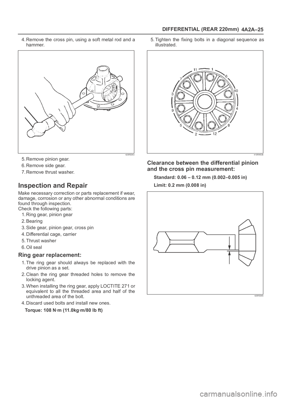
Torque: 108 Nꞏm (11.0kgꞏm/80 lb ft)5. Tighten the fixing bolts in a diagonal sequence as
illustrated.
415RW036
Clearance between the differential pinion
and the cross pin measurement:
Standard: 0.06 – 0.12 mm (0.002–0.005 in)
Limit: 0.2 mm (0.008 in)
425RS045
Page 3999 of 6000
4A2A–30
DIFFERENTIAL (REAR 220mm)
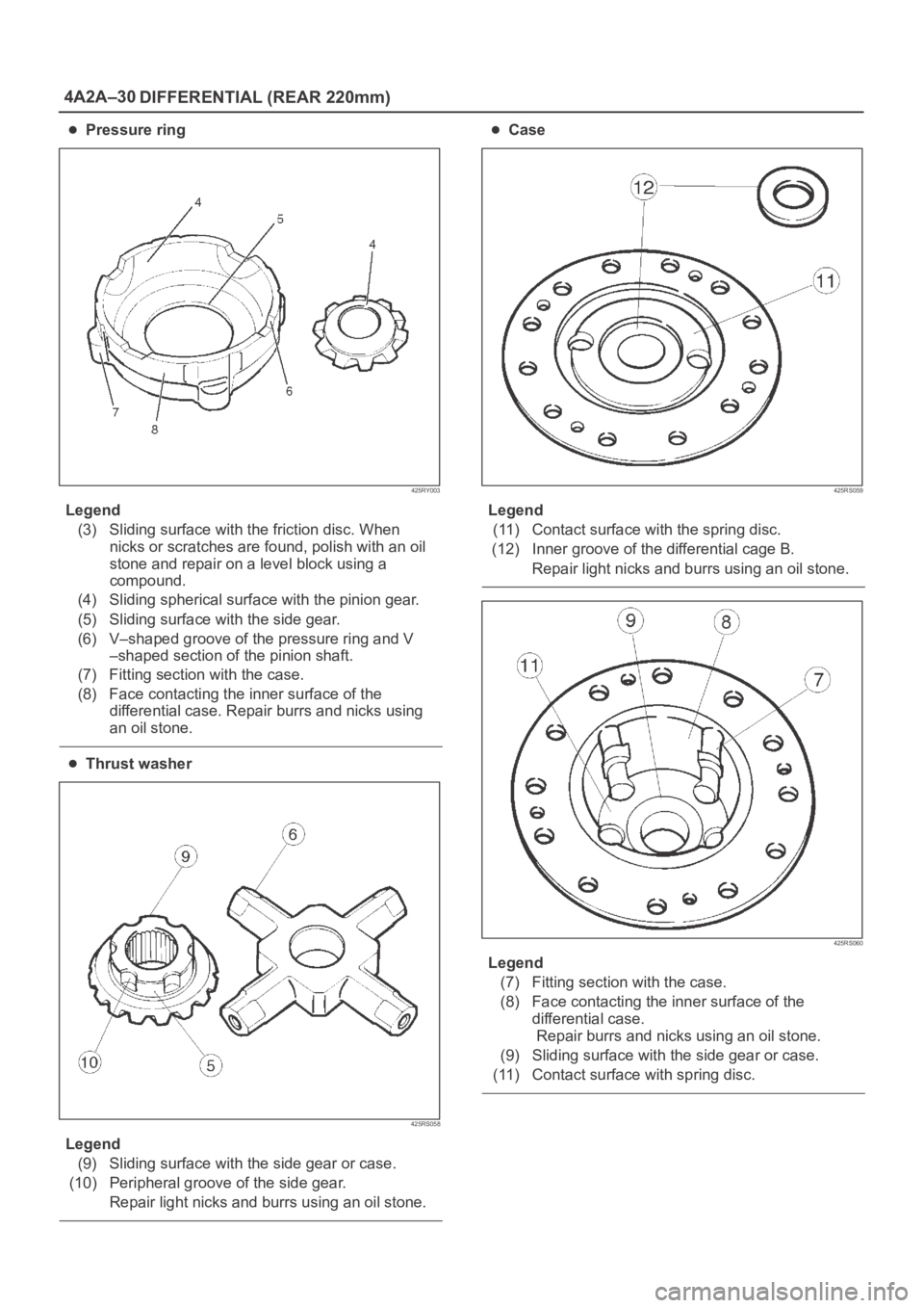
Pressure ring
425RY003
Legend
(3) Sliding surface with the friction disc. When
nicks or scratches are found, polish with an oil
stone and repair on a level block using a
compound.
(4) Sliding spherical surface with the pinion gear.
(5) Sliding surface with the side gear.
(6) V–shaped groove of the pressure ring and V
–shaped section of the pinion shaft.
(7) Fitting section with the case.
(8) Face contacting the inner surface of the
differential case. Repair burrs and nicks using
an oil stone.
Thrust washer
425RS058
Legend
(9) Sliding surface with the side gear or case.
(10) Peripheral groove of the side gear.
Repair light nicks and burrs using an oil stone.
Case
425RS059
Legend
(11) Contact surface with the spring disc.
(12) Inner groove of the differential cage B.
Repair light nicks and burrs using an oil stone.
425RS060
Legend
(7) Fitting section with the case.
(8) Face contacting the inner surface of the
differential case.
Repair burrs and nicks using an oil stone.
(9) Sliding surface with the side gear or case.
(11) Contact surface with spring disc.
Page 4002 of 6000
DIFFERENTIAL (REAR 220mm)
4A2A–33
3. After measuring dimensions of each of the above
sections, proceed with the adjustment in the following
manner:
Adjust the clearance to satisfy the equation below.
{(F – B) + G – H}=0.05 – 0.20 mm
Also, select the thrust washers so that the
dimensional difference between the back surfaces of
the left and right pressure rings to the thrust washers
is 0.05mm or less.
Thickness : 1.5mm (0.059 in)
1.6 mm(0.063 in)
1.7 mm(0.067 in)
NOTE: When assembling the parts, apply recommended
gear oil sufficiently to each of the parts, especially, to the
contact surfaces and sliding surfaces.
1. Install Differential cage B.
2. Install Thrust washer.
3. Install Spring disc.
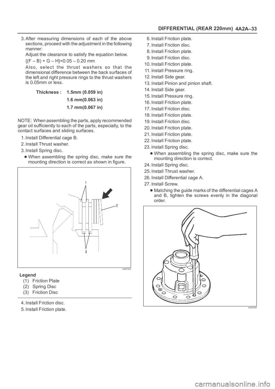
When assembling the spring disc, make sure the
mounting direction is correct as shown in figure.
425RY004
Legend
(1) Friction Plate
(2) Spring Disc
(3) Friction Disc
4. Install Friction disc.
5. Install Friction plate.6. Install Friction plate.
7. Install Friction disc.
8. Install Friction plate.
9. Install Friction disc.
10. Install Friction plate.
11. Install Pressure ring.
12. Install Side gear.
13. Install Pinion and pinion shaft.
14. Install Side gear.
15. Install Pressure ring.
16. Install Friction plate.
17. Install Friction disc.
18. Install Friction plate.
19. Install Friction disc.
20. Install Friction plate.
21. Install Friction plate.
22. Install Friction plate.
23. Install Spring disc.
When assembling the spring disc, make sure the
mounting direction is correct.
24. Install Spring disc.
25. Install Thrust washer.
26. Install Differential cage A.
27. Install Screw.
Matching the guide marks of the differential cages A
and B, tighten the screws evenly in the diagonal
order.
425RS055
Page 4006 of 6000
DIFFERENTIAL (REAR 220mm)
4A2A–37
Special Tools
ILLUSTRATIONTOOL NO.
TOOL NAME
5–8840–2157–0
(J–37221)
Holder; Pinion flange
5–8840–2294–0
(J–24250)
Installer; Oil seal
5–8840–0275–0
(J–37264)
Differential holding
fixture
(Use with
5–8840–0003–0)
5–8840–0003–0
(J–3289–20)
Holding fixture base
5–8840–0013–0
5–8840–0014–0
(J–22888)
Puller; Side bearing
5–8840–2196–0
(J–8107–2)
Adapter; Side bearing
plug
ILLUSTRATIONTOOL NO.
TOOL NAME
5–8840–2197–0
(J–22912–01)
Separator
5–8840–2164–0
(J–24256)
Installer; Outer bearing
outer race
5–8840–0007–0
(J–8092)
Driver handle
5–8840–2163–0
(J–24252)
Installer; Inner bearing
outer race
5–8840–2085–0
(J–21777–42)
Front Pilot
5–8840–0127–0
(J–23597–9)
Nut and bolt