Page 700 of 6000

4C–34
DRIVE SHAFT SYSTEM
NOTE: Be careful not to damage seal.
6. Install snap ring (internal) in the groove of front axle
case.
NOTE: Be sure to install the snap ring properly.
412RW017
7. Apply differential gear oil to clutch gear, then install
clutch gear.
8. Apply differential gear oil to sleeve, then install
sleeve.
9. Clean contact surface with the front axle and actuator
mounting surface. Apply liquid gasket to the contact
surface on the front axle case, then install in the
housing.
412RW023
10. Tighten bolts to specified torque.
Torque: 116Nꞏm (11.8 kgꞏm/85 lb ft)11. Clean the actuator contact surface with the housing
then Install and tighten shift position switch to
specified torque.
Torque: 39Nꞏm (4.0 kgꞏm/29 lb ft)
12. Apply liquid gasket to the contact surface on the
actuator side.
412RW012
13. Align shift arm with the groove of sleeve and install the
actuator.
14. Tighten bolts to specified torque.
Torque: 13Nꞏm (1.3 kgꞏm/113 lb in)
15. Install front axle drive shaft and mounting bracket.
Tighten fitting bolts to specified torque.
Torque: 116Nꞏm (11.8 kgꞏm/85 lb ft)
16. Pour specified amount of differential gear oil to filler
plug.
Front Differential
Oil Capacity: 1.4lit (1.23 Imp qt/1.48 US qt)
Actuator Housing
Oil Capacity: 0.12lit (0.10 Imp qt/0.13 US qt)
17. Install filler plug through gasket and tighten to
specified torque.
To r q u e : 7 8 N ꞏm ( 5 8 l b f t )
Page 701 of 6000
4C–35 DRIVE SHAFT SYSTEM
Main Data and Specifications
General Specifications
Front drive axle oil capacity1.4 liter (1.23 Imp qt/1.48 US qt)(Differential)
0.12 liter (0.10 Imp qt/0.13 US qt)(Actuator Housing:Shift on the fly)
Type of lubricantGL–5 (Multi grade type) Refer to chart in General Information
Axle shaft typeConstant velocity joint(Birfield joint type and double offset joint)
Torque Specifications
E04RW020
Page 705 of 6000

4C–39 DRIVE SHAFT SYSTEM
401RW053
401RW052
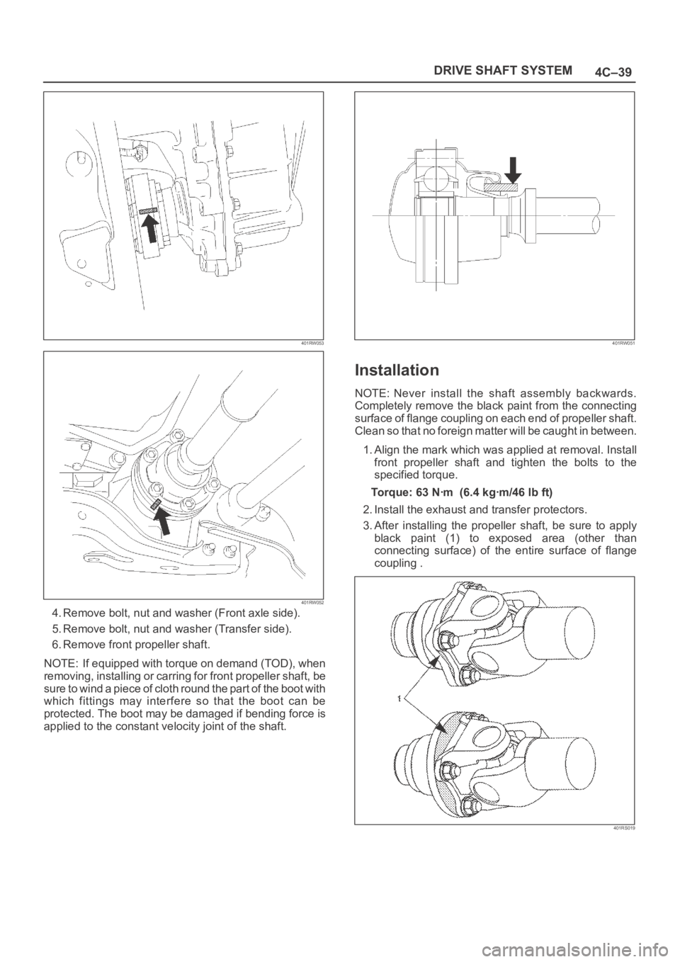
4. Remove bolt, nut and washer (Front axle side).
5. Remove bolt, nut and washer (Transfer side).
6. Remove front propeller shaft.
NOTE: If equipped with torque on demand (TOD), when
removing, installing or carring for front propeller shaft, be
sure to wind a piece of cloth round the part of the boot with
which fittings may interfere so that the boot can be
protected. The boot may be damaged if bending force is
applied to the constant velocity joint of the shaft.
401RW051
Installation
NOTE: Never install the shaft assembly backwards.
Completely remove the black paint from the connecting
surface of flange coupling on each end of propeller shaft.
Clean so that no foreign matter will be caught in between.
1. Align the mark which was applied at removal. Install
front propeller shaft and tighten the bolts to the
specified torque.
Torque:63Nꞏm (6.4kgꞏm/46lbft)
2. Install the exhaust and transfer protectors.
3. After installing the propeller shaft, be sure to apply
black paint (1) to exposed area (other than
connecting surface) of the entire surface of flange
coupling .
401RS019
Page 713 of 6000
4C–47 DRIVE SHAFT SYSTEM
Main Data and Specifications
General Specifications
Engine6VE1 (3.5L)6VD1 (3.2L)4JX1 (3.0L)4JG2 (3.1L)
Transmission
M/TA/T
A/T
with
TOD
M/TA/T
A/T
with
TOD
M/TA/TM/TA/T
Construction
Hollow steel tube
with yoke and
spider type
universal joint
Hollow
steel
tube
with
consta
nt
velocity
joints
Hollow steel tube
with yoke and
spider type
universal joint
Hollow
steel
tube
with
consta
nt
velocity
joints
Hollow steel tube with yoke and
spider type universal joint
Outside
diameter40.0mm (1.57 in)
Length559mm
(22.01in)559mm
(22.01in)577mm
(22.72in)393mm
(15.47in)559mm
(22.01in)577mm
(22.72in)627mm
(24.69in)627mm
(24.69in)421mm
(16.57in)627mm
(24.69in)
Torque Specifications
E04RW021
Page 715 of 6000
4C–49 DRIVE SHAFT SYSTEM
Removal
1. Jack up the vehicle and support it on the chassis
stands.
2. Gear shift lever should be placed in neutral position
and parking brake released.
NOTE: Apply alignment marks on the flange at the rear
propeller shaft both front and rear side.
401RS023
3. Remove bolt, nut and washer (Rear axle side).
4. Remove bolt, nut and washer (Transfer side).
5. Remove rear propeller shaft.
Installation
NOTE: Never install the shaft assembly backwards.
1. Completely remove the black paint from the
connecting surface of flange coupling on each end of
propeller shaft. Clean so that no foreign matter will be
caught in between.
2. Align the mark which is applied at removal .
Install rear propeller shaft and tighten the bolts to the
specified torque.
Torque: 63 Nꞏm (6.4 kgꞏm/46 lb ft)3. After installing the propeller shaft, be sure to apply
black paint (1) to exposed area (other than
connecting surface) of the entire surface of flange
coupling .
401RS022
Page 721 of 6000
4C–55 DRIVE SHAFT SYSTEM
Main Data and Specifications
General Specifications
Engine6VE1 (3.5L)6VD1 (3.2L)4JX1 (3.0L)4JG2 (3.1L)
Transmission
M/TA/T
A/T
with
TOD
M/TA/T
A/T
with
TOD
M/TA/TM/TA/T
ConstructionHollow steel tube with yoke and spider type universal joint
LengthS
W
B
668mm (26.30in)—846mm
(33.31in)678mm
(26.69in)—604mm (23.78in)810mm
(31.89in)—
L
W
B
1093mm (43.03in)1075mm
(42.32in)1271mm
(50.04in)1103mm
(43.43in)1083mm
(42.64in)1029mm (40.51in)1236mm
(48.66in)1037mm
(40.83in)
Outside
diamterS
W
B
68.9mm (2.71in)—68.9mm (2.71in)—68.9mm (2.71in)—
LW
B68.9mm (2.71in)82.6mm
(3.25in)68.9mm (2.71in)82.6mm
(3.25in)68.9mm
(2.71in)
Torque Specifications
E04RW023
Page 722 of 6000

TRANSFER CASE (STANDARD TYPE)
4D1–1
DRIVELINE/AXLE
TRANSFER CASE (STANDARD TYPE)
CONTENTS
Service Precaution 4D1–1. . . . . . . . . . . . . . . . . . . . . .
General Description 4D1–2. . . . . . . . . . . . . . . . . . . . .
Transfer Rear Oil Seal 4D1–8. . . . . . . . . . . . . . . . . . .
Removal 4D1–8. . . . . . . . . . . . . . . . . . . . . . . . . . . . .
Installation 4D1–8. . . . . . . . . . . . . . . . . . . . . . . . . . . .
Transfer Case Assembly 4D1–9. . . . . . . . . . . . . . . . .
Removal 4D1–9. . . . . . . . . . . . . . . . . . . . . . . . . . . . .
Installation 4D1–10. . . . . . . . . . . . . . . . . . . . . . . . . . . .
Transfer Rear Cover Assembly
(4WD Switch Model) 4D1–11. . . . . . . . . . . . . . . . . . . .
Transfer Rear Cover Assembly and
Associated Parts 4D1–11. . . . . . . . . . . . . . . . . . . . . .
Removal 4D1–12. . . . . . . . . . . . . . . . . . . . . . . . . . . . .
Installation 4D1–13. . . . . . . . . . . . . . . . . . . . . . . . . . . .
Disassembly 4D1–16. . . . . . . . . . . . . . . . . . . . . . . . . .
Inspection and Repair 4D1–17. . . . . . . . . . . . . . . . . .
Reassembly 4D1–17. . . . . . . . . . . . . . . . . . . . . . . . . .
Transfer Rear Cover Assembly
(Except 4WD Switch Model) 4D1–19. . . . . . . . . . . . . . Transfer Rear Cover Assembly and
Associated Parts 4D1–19. . . . . . . . . . . . . . . . . . . . . .
Removal 4D1–20. . . . . . . . . . . . . . . . . . . . . . . . . . . . .
Installation 4D1–20. . . . . . . . . . . . . . . . . . . . . . . . . . . .
Disassembly 4D1–23. . . . . . . . . . . . . . . . . . . . . . . . . .
Inspection and Repair 4D1–24. . . . . . . . . . . . . . . . . .
Reassembly 4D1–24. . . . . . . . . . . . . . . . . . . . . . . . . .
Detent, Shift Arm, and Interlock Pin 4D1–26. . . . . . . .
Disassembled View 4D1–26. . . . . . . . . . . . . . . . . . . .
Disassembly 4D1–26. . . . . . . . . . . . . . . . . . . . . . . . . .
Inspection and Repair 4D1–28. . . . . . . . . . . . . . . . . .
Reassembly 4D1–28. . . . . . . . . . . . . . . . . . . . . . . . . .
Transfer Case Assembly 4D1–30. . . . . . . . . . . . . . . . .
Disassembled View 4D1–30. . . . . . . . . . . . . . . . . . . .
Disassembly 4D1–31. . . . . . . . . . . . . . . . . . . . . . . . . .
Inspection and Repair 4D1–33. . . . . . . . . . . . . . . . . .
Reassembly 4D1–37. . . . . . . . . . . . . . . . . . . . . . . . . .
Main Data and Specifications 4D1–43. . . . . . . . . . . . .
Special Tools 4D1–46. . . . . . . . . . . . . . . . . . . . . . . . . . .
Service Precaution
WARNING: THIS VEHICLE HAS A SUPPLEMENTAL
RESTRAINT SYSTEM (SRS). REFER TO THE SRS
COMPONENT AND WIRING LOCATION VIEW IN
ORDER TO DETERMINE WHETHER YOU ARE
PERFORMING SERVICE ON OR NEAR THE SRS
COMPONENTS OR THE SRS WIRING. WHEN YOU
ARE PERFORMING SERVICE ON OR NEAR THE SRS
COMPONENTS OR THE SRS WIRING, REFER TO
THE SRS SERVICE INFORMATION. FAILURE TO
FOLLOW WARNINGS COULD RESULT IN POSSIBLE
AIR BAG DEPLOYMENT, PERSONAL INJURY, OR
OTHERWISE UNNEEDED SRS SYSTEM REPAIRS.
CAUTION: Always use the correct fastener in the
proper location. When you replace a fastener, use
ONLY the exact part number for that application.
ISUZU will call out those fasteners that require a
replacement after removal. ISUZU will also call out
the fasteners that require thread lockers or thread
sealant. UNLESS OTHERWISE SPECIFIED, do not
use supplemental coatings (Paints, greases, or other
corrosion inhibitors) on threaded fasteners or
fastener joint interfaces. Generally, such coatings
adversely affect the fastener torque and the joint
clamping force, and may damage the fastener. When
you install fasteners, use the correct tightening
sequence and specifications. Following these
instructions can help you avoid damage to parts and
systems.
Page 729 of 6000

4D1–8
TRANSFER CASE (STANDARD TYPE)
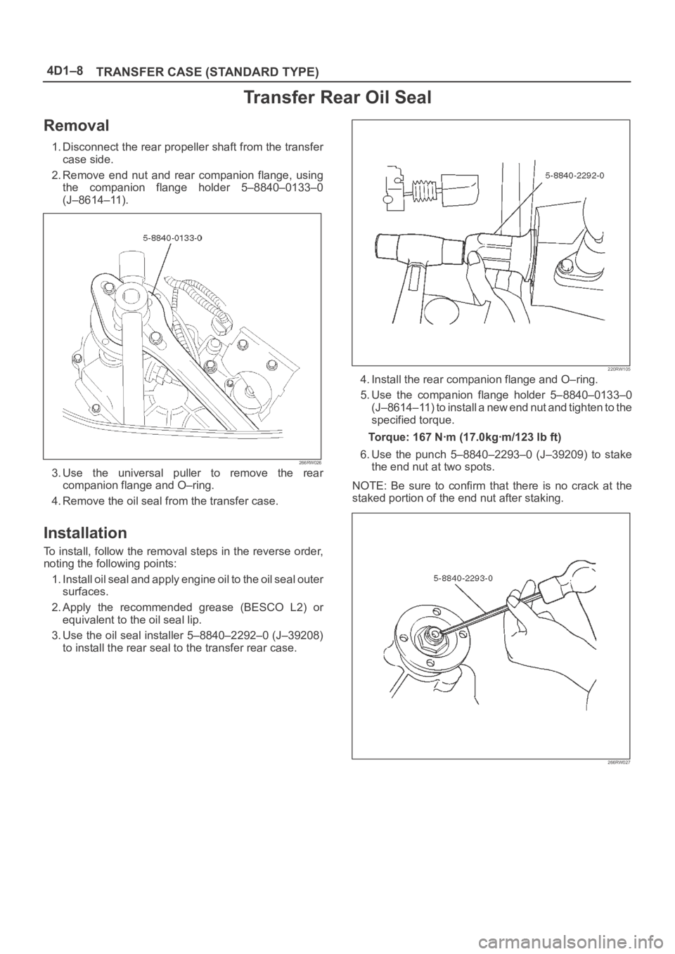
Transfer Rear Oil Seal
Removal
1. Disconnect the rear propeller shaft from the transfer
case side.
2. Remove end nut and rear companion flange, using
the companion flange holder 5–8840–0133–0
(J–8614–11).
266RW026
3. Use the universal puller to remove the rear
companion flange and O–ring.
4. Remove the oil seal from the transfer case.
Installation
To install, follow the removal steps in the reverse order,
noting the following points:
1. Install oil seal and apply engine oil to the oil seal outer
surfaces.
2. Apply the recommended grease (BESCO L2) or
equivalent to the oil seal lip.
3. Use the oil seal installer 5–8840–2292–0 (J–39208)
to install the rear seal to the transfer rear case.
220RW105
4. Install the rear companion flange and O–ring.
5. Use the companion flange holder 5–8840–0133–0
(J–8614–11) to install a new end nut and tighten to the
specified torque.
Torque: 167 Nꞏm (17.0kgꞏm/123 lb ft)
6. Use the punch 5–8840–2293–0 (J–39209) to stake
the end nut at two spots.
NOTE: Be sure to confirm that there is no crack at the
staked portion of the end nut after staking.
266RW027