Page 2605 of 6000
Parts for Electrical Circuit
Wiring – Wire color
All wires have color–coded insulation.
Wires belonging to a system’s main harness will have a
single color (1). Wires belonging to a system’s subcircuits
will have a colored stripe (2). Striped wires use the
following code to show wire size and colors.
Example: 0.5 G / R
Red (Stripe color)
Green (Base color)
Wire size (0.5 mm
2)
Wiring – Wire Color Coding
Abbreviations are used to indicate wire color within a circuit diagram.
Refer to the following table.
Color Coding Meaning Color Coding Meaning
B Black BR Brown
W White LG Light green
RRedGRGrey
G Green P Pink
Y Yellow LB Light blue
LBlue VViolet
OOrange
1
2
Page 3458 of 6000

SUPPLEMENTAL RESTRAINT SYSTEM9J–21
THROUGHOUT THIS ENTIRE DEPLOYMENT AND
DISPOSAL PROCEDURE.
9. Twist together one connector wire lead to one
deployment wire. The connection should be
mechanically secure.
10. Bend twisted connection made in the previous step
flat and wrap tightly with electrical tape to insulate and
secure.
11. Twist together, bend and tape the remaining
connector wire lead to the remaining deployment
wire.
12. Connect the deployment harness to the driver air bag
assembly, yellow 2–pin connector at the base of the
steering column. Route deployment harness out the
driver side of the vehicle.
WARNING: DEPLOYMENT WIRES SHALL REMAIN
SHORTED AND NOT BE CONNECTED TO A POWER
SOURCE UNTIL THE AIR BAG IS TO BE DEPLOYED.
THE AIR BAG ASSEMBLY WILL IMMEDIATELY
DEPLOY THE AIR BAG WHEN A POWER SOURCE IS
CONNECTED TO IT.
CONNECTING THE DEPLOYMENT WIRES TO THE
POWER SOURCE SHOULD ALWAYS BE THE FINAL
STEP IN THE AIR BAG ASSEMBLY DEPLOYMENT
PROCEDURE.
FAILURE TO FOLLOW PROCEDURES IN THE
ORDER LISTED COULD RESULT IN PERSONAL
INJURY.
13. Disconnect passenger air bag assembly, yellow 2–pin
connector located behind glove box assembly.
14. Cut the passenger air bag assembly harness
connector from the vehicle leaving at least 15 cm (six
inches) of wire at the connector.
15. Strip 13 mm (1/2 inch) of insulation from blue–white
and pink–blue wire lead of the connector.
16. Cut two 900 cm (30 feet) deployment wires from 0.8
mm
(18 gauge) or thicker multi–strand wire. These
wires will be used to fabricate the passenger
deployment harness.
17. Strip 13 mm (1/2 inch) of insulation from both ends of
the wires cut in the previous step.
18. Short the wires by twisting together one end from
each. Deployment wires shall remain shorted and not
be connected to a power source until the air bag is to
be deployed.
WARNING: FAILURE TO FOLLOW PROCEDURES IN
THE ORDER LISTED COULD RESULT IN PERSONAL
INJURY. NEVER CONNECT DEPLOYMENT WIRES
TO ANY POWER SOURCE BEFORE CONNECTING
DEPLOYMENT WIRES TO THE AIR BAG ASSEMBLY
LEADS. DEPLOYMENT WIRES SHALL REMAIN
SHORTED AND NOT BE CONNECTED TO A POWER
SOURCE UNTIL THE AIR BAG IS TO BE DEPLOYED.
THE AIR BAG ASSEMBLY WILL IMMEDIATELY
DEPLOY THE AIR BAG WHEN A POWER SOURCE IS
CONNECTED TO IT. WEAR SAFETY GLASSES
THROUGHOUT THIS ENTIRE DEPLOYMENT AND
DISPOSAL PROCEDURE.19. Twist together one connector wire lead to one
deployment wire. The connection should be
mechanically secure.
20. Bend twisted connection made in the previous step
flat and wrap tightly with electrical tape to insulate and
secure.
21. Twist together, bend and tape the remaining
connector wire lead to the remaining deployment
wire.
22. Connect the deployment harness to the passenger air
bag assembly, yellow 2–pin connector located behind
the glove box assembly. Route deployment harness
out the passenger side of the vehicle.
WARNING: DEPLOYMENT WIRES SHALL REMAIN
SHORTED AND NOT BE CONNECTED TO A POWER
SOURCE UNTIL THE AIR BAG IS TO BE DEPLOYED.
THE AIR BAG ASSEMBLY WILL IMMEDIATELY
DEPLOY THE AIR BAG WHEN A POWER SOURCE IS
CONNECTED TO IT. CONNECTING THE
DEPLOYMENT WIRES SHOULD ALWAYS BE THE
FINAL STEP IN THE AIR BAG ASSEMBLY
DEPLOYMENT PROCEDURE. FAILURE TO FOLLOW
PROCEDURES IN THE ORDER LISTED COULD
RESULT IN PERSONAL INJURY.
23. Verify that the inside of the vehicle and the area
surrounding the vehicle are clear of all people and
loose or flammable objects.
24. Stretch the driver and passenger deployment
harness to their full length.
25. Completely cover windshield area and front door
window openings with a drop cloth, blanket or similar
item. This reduces the possibility of injury due to
possible fragmentation of the vehicle’s glass or
interior.
26. Notify all people in the immediate area that you intend
to deploy the air bags. The deployment will be
accompanied by a substantial noise which may
startle the uninformed.
27. Separate the two ends of the driver deployment
harness wires.
WARNING: DEPLOYMENT WIRES SHALL REMAIN
SHORTED AND NOT BE CONNECTED TO A POWER
SOURCE UNTIL THE AIR BAG IS TO A POWER
SOURCE UNTIL THE AIR BAG IS TO BE DEPLOYED.
THE AIR BAG ASSEMBLY WILL IMMEDIATELY
DEPLOY THE AIR BAG WHEN A POWER SOURCE IS
CONNECTED TO IT. CONNECTING THE
DEPLOYMENT WIRES TO THE POWER SOURCE
SHOULD ALWAYS BE THE FINAL STEP IN THE AIR
BAG ASSEMBLY DEPLOYMENT PROCEDURE.
FAILURE TO FOLLOW PROCEDURES IN THE
ORDER LISTED COULD RESULT IN PERSONAL
INJURY.
NOTE: When the air bag deploys, the rapid gas
expansion will create a substantial noise. Notify all
people in the immediate area that you intend to deploy the
air bags.
Page 3710 of 6000
C01RY00001
2
1
123
4
10
96 5
87
11
13
B
B
A
C
B
C
A
ABB
A
A
B
A
A
B
B
A
C
A
A
C
CC
B
AB
AABB
Vent DoorM o d e P o s i t i o n Display of Intake Status S e t T e m p e r a t u r e
ONFULL
COLDFULL
HOT 20~30
℃
〜
BBAA〜
Blue
VENT BI-LEVEL FOOT DEFRed
OFF
Foot Door
DEF Door
Intake Door
Air Mix Door
Sub Air Mix DoorWhite
C
C
B
DEF/FOOT
C
A
Page 3959 of 6000
4A1–19 DIFFERENTIAL (FRONT)
17. Tighten the cap bolt to the specified torque.
To r q u e : 9 8 N ꞏm ( 1 0 k g ꞏm / 7 2 l b f t )
425RS036
1. Measure the amount of run–out of the ring gear at
its rear face.
Standard: 0.02 mm ( 0.001 in)
Limit: 0.05 mm ( 0.002 in)
425RS037
Gear Tooth Contact Pattern Check and Adjustment
1. Apply a thin coat of prussian blue or equivalent
to the faces of the 7–8 teeth of the ring gear.
Check the impression of contact on the ring
gear teeth and make necessary adjustment as
described in illustration if the contact is
abnormal.
425RS038
Legend
(1) Heel
(2) Toe
(3) Concave Side(Coast)
(4) Convex Side(Drive)
Page 3991 of 6000
4A2A–22
DIFFERENTIAL (REAR 220mm)
17. Tighten the cap bolt to the specified torque.
Torque: 108 Nꞏm (11.0kgꞏm/80 lb ft)
425RS036
1. Measure the amount of run–out of the ring gear at
its rear face.
Standard: 0.02 mm ( 0.001 in)
Limit: 0.05 mm ( 0.002 in)
425RS037
Gear Tooth Contact Pattern Check and Adjustment
1. Apply a thin coat of prussian blue or equivalent
to the faces of the 7–8 teeth of the ring gear.
Check the impression of contact on the ring
gear teeth and make necessary adjustment as
described in illustration if the contact is
abnormal.
425RS038
Legend
(1) Heel
(2) Toe
(3) Concave Side(Coast)
(4) Convex Side(Drive)
Page 4030 of 6000
DIFFERENTIAL (REAR 244mm)
4A2B–23
16. Tighten the bolt to the specified torque.
Torque:108Nꞏm (11.0kgꞏm/80 lb ft)
425RS036
Gear Tooth Contact Pattern Check and Adjustment
1. Apply a thin coat of Prussian blue or equivalent to the
faces of the 7–8 teeth of the ring gear. Check the
impression of contact on the ring gear teeth and make
necessary adjustment as described in illustration if
the contact is abnormal.
425RS038
Legend
(1) Heel
(2) Toe
(3) Concave Side(Coast)
(4) Convex Side(Drive)
425RS039
Page 4050 of 6000
4B1–5 DRIVE LINE CONTROL SYSTEM (SHIFT ON THE FLY)
4. If vacuum is not applicable as much as –400mmHg,
and if there is resistance on the intake side, replace
with a new check valve.
VSV Assembly
Inspect the vehicle side harness as follows:
412RS071
Legend
(1) Grey
(2) Blue
1. Remove connector.
2. Shift transfer lever to 2H and start the engine.
NOTE: Do not move the vehicle while inspection.
3. Make sure that there is continuity in the vehicle side of
harness. If there is no continuity, check transfer shift
switch and wiring.
Inspect both VSVs as follows:
F04RS004
1. With battery not connected (Usual).
A–C:There is continuity
B:Closed
2. With battery connected
A – B:There is continuity
C:Closed
3. If 1) and 2) fail, replace with a new VSV.
Axle Position Switch
412RS048
1. With ball (1) being free
A – B:There is continuity
2. With ball forced into the switch
A – B:No continuity
3. If 1) and 2) fail, replace with a new switch.
Page 4079 of 6000

4B1–34
DRIVE LINE CONTROL SYSTEM (SHIFT ON THE FLY)
4. If vacuum is not applicable as much as –400mmHg,
and if there is resistance on the intake side, replace
with a new check valve.
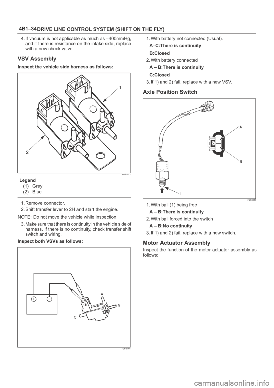
VSV Assembly
Inspect the vehicle side harness as follows:
412RS071
Legend
(1) Grey
(2) Blue
1. Remove connector.
2. Shift transfer lever to 2H and start the engine.
NOTE: Do not move the vehicle while inspection.
3. Make sure that there is continuity in the vehicle side of
harness. If there is no continuity, check transfer shift
switch and wiring.
Inspect both VSVs as follows:
F04RS004
1. With battery not connected (Usual).
A–C:There is continuity
B:Closed
2. With battery connected
A – B:There is continuity
C:Closed
3. If 1) and 2) fail, replace with a new VSV.
Axle Position Switch
412RS048
1. With ball (1) being free
A – B:There is continuity
2. With ball forced into the switch
A – B:No continuity
3. If 1) and 2) fail, replace with a new switch.
Motor Actuator Assembly
Inspect the function of the motor actuator assembly as
follows: