1998 OPEL FRONTERA ad blue
[x] Cancel search: ad bluePage 4842 of 6000
6E–185 ENGINE DRIVEABILITY AND EMISSIONS
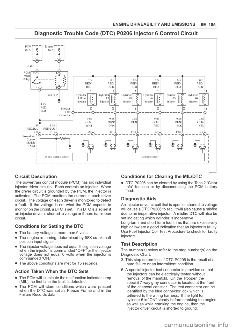
Diagnostic Trouble Code (DTC) P0206 Injector 6 Control Circuit
D06RW034
Circuit Description
The powertrain control module (PCM) has six individual
injector driver circuits. Each controls an injector. When
the driver circuit is grounded by the PCM, the injector is
activated. The PCM monitors the current in each driver
circuit. The voltage on each driver is monitored to detect
a fault. If the voltage is not what the PCM expects to
m o n i t o r o n t h e c i r c u i t , a D T C i s s e t . T h i s D T C i s a l s o s e t i f
an injector driver is shorted to voltage or if there is an open
circuit.
Conditions for Setting the DTC
The battery voltage is more than 9 volts.
The engine is turning, determined by 58X crankshaft
position input signal.
The injector voltage does not equal the ignition voltage
when the injector is commanded “OFF” or the injector
voltage does not equal 0 volts when the injector is
commanded “ON.”
The above conditions are met for 15 seconds.
Action Taken When the DTC Sets
The PCM will illuminate the malfunction indicator lamp
(MIL) the first time the fault is detected.
The PCM will store conditions which were present
when the DTC was set as Freeze Frame and in the
Failure Records data.
Conditions for Clearing the MIL/DTC
DTC P0206 can be cleared by using the Tech 2 “Clear
Info” function or by disconnecting the PCM battery
feed.
Diagnostic Aids
An injector driver circuit that is open or shorted to voltage
will cause a DTC P0206 to set. It will also cause a misfire
due to an inoperative injector. A misfire DTC will also be
set indicating which cylinder is inoperative.
Long term and short term fuel trims that are excessively
high or low are a good indication that an injector is faulty.
Use Fuel Injector Coil Test Procedure to check for faulty
injectors.
Test Description
The number(s) below refer to the step number(s) on the
Diagnostic Chart.
3. This step determines if DTC P0206 is the result of a
hard failure or an intermittent condition.
5. A special injector test connector is provided so that
the injectors can be electrically tested without
removal of the manifold. On the Trooper, the
special 7-way gray connector is located at the front
of the charcoal canister. The test connector can be
identified by the blue connector lock which is
tethered to the wiring harness. If the light for
cylinder 6 is “ON” steady before cranking the engine
as well as while cranking the engine, then the
injector driver circuit is shorted to ground.
Page 4844 of 6000
6E–187 ENGINE DRIVEABILITY AND EMISSIONS
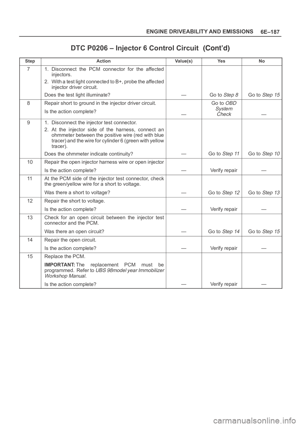
DTC P0206 – Injector 6 Control Circuit
StepNo Ye s Va l u e ( s ) Action
71. Disconnect the PCM connector for the affected
injectors.
2. With a test light connected to B+, probe the affected
injector driver circuit.
Does the test light illuminate?
—Go to Step 8Go to Step 15
8Repair short to ground in the injector driver circuit.
Is the action complete?
—
Go to OBD
System
Check
—
91. Disconnect the injector test connector.
2. At the injector side of the harness, connect an
ohmmeter between the positive wire (red with blue
tracer) and the wire for cylinder 6 (green with yellow
tracer).
Does the ohmmeter indicate continuity?
—Go to Step 11Go to Step 10
10Repair the open injector harness wire or open injector
Is the action complete?
—Verify repair—
11At the PCM side of the injector test connector, check
the green/yellow wire for a short to voltage.
Was there a short to voltage?
—Go to Step 12Go to Step 13
12Repair the short to voltage.
Is the action complete?
—Verify repair—
13Check for an open circuit between the injector test
connector and the PCM.
Was there an open circuit?
—Go to Step 14Go to Step 15
14Repair the open circuit.
Is the action complete?
—Verify repair—
15Replace the PCM.
IMPORTANT:The replacement PCM must be
programmed. Refer to
UBS 98model year Immobilizer
Workshop Manual.
Is the action complete?—Verify repair—
Page 4848 of 6000
6E–191 ENGINE DRIVEABILITY AND EMISSIONS
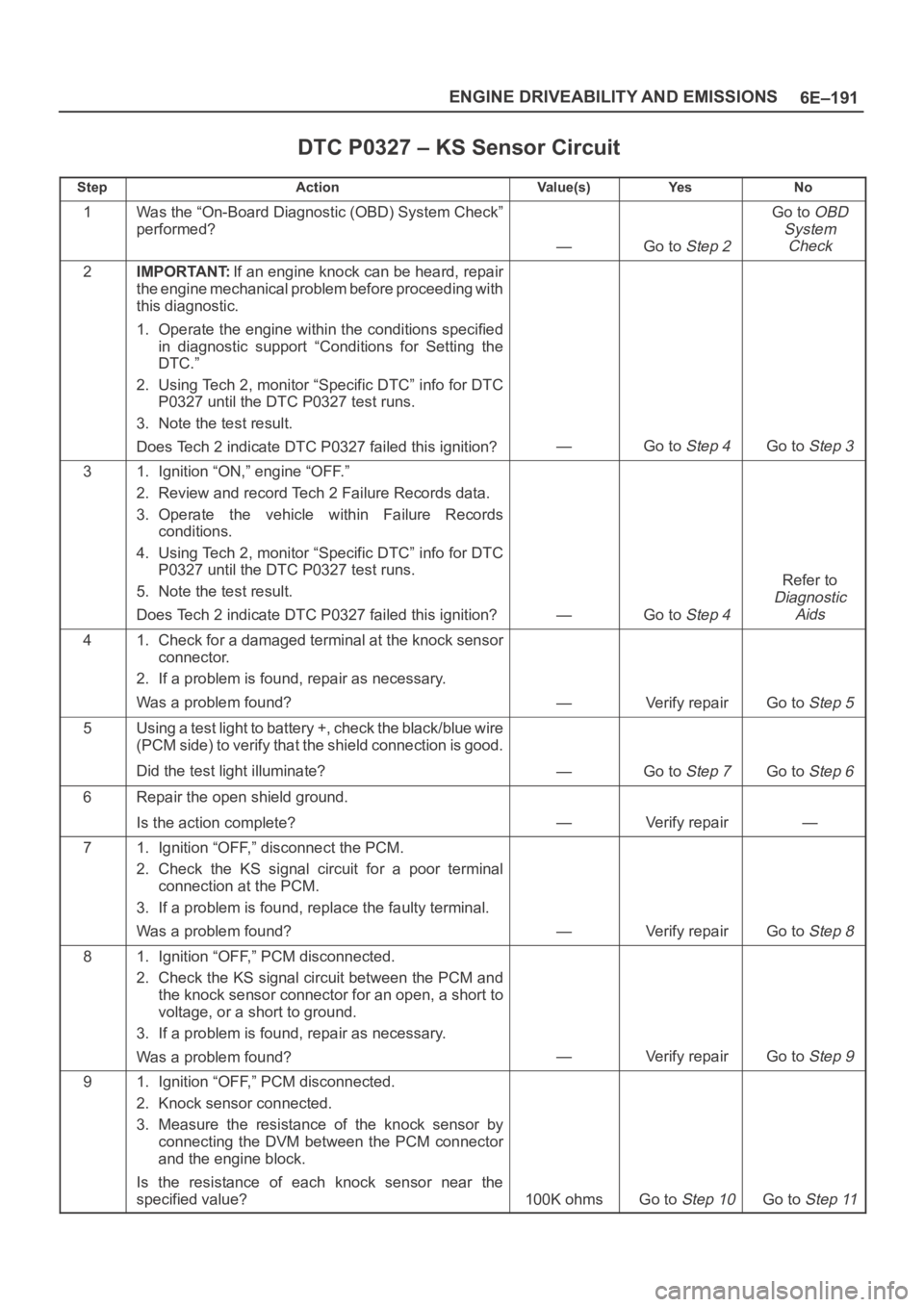
DTC P0327 – KS Sensor Circuit
StepActionVa l u e ( s )Ye sNo
1Was the “On-Board Diagnostic (OBD) System Check”
performed?
—Go to Step 2
Go to OBD
System
Check
2IMPORTANT:If an engine knock can be heard, repair
the engine mechanical problem before proceeding with
this diagnostic.
1. Operate the engine within the conditions specified
in diagnostic support “Conditions for Setting the
DTC.”
2. Using Tech 2, monitor “Specific DTC” info for DTC
P0327 until the DTC P0327 test runs.
3. Note the test result.
Does Tech 2 indicate DTC P0327 failed this ignition?
—Go to Step 4Go to Step 3
31. Ignition “ON,” engine “OFF.”
2. Review and record Tech 2 Failure Records data.
3. Operate the vehicle within Failure Records
conditions.
4. Using Tech 2, monitor “Specific DTC” info for DTC
P0327 until the DTC P0327 test runs.
5. Note the test result.
Does Tech 2 indicate DTC P0327 failed this ignition?
—Go to Step 4
Refer to
Diagnostic
Aids
41. Check for a damaged terminal at the knock sensor
connector.
2. If a problem is found, repair as necessary.
Was a problem found?
—Verify repairGo to Step 5
5Using a test light to battery +, check the black/blue wire
(PCM side) to verify that the shield connection is good.
Did the test light illuminate?
—Go to Step 7Go to Step 6
6Repair the open shield ground.
Is the action complete?
—Verify repair—
71. Ignition “OFF,” disconnect the PCM.
2. Check the KS signal circuit for a poor terminal
connection at the PCM.
3. If a problem is found, replace the faulty terminal.
Was a problem found?
—Verify repairGo to Step 8
81. Ignition “OFF,” PCM disconnected.
2. Check the KS signal circuit between the PCM and
the knock sensor connector for an open, a short to
voltage, or a short to ground.
3. If a problem is found, repair as necessary.
Was a problem found?
—Verify repairGo to Step 9
91. Ignition “OFF,” PCM disconnected.
2. Knock sensor connected.
3. Measure the resistance of the knock sensor by
connecting the DVM between the PCM connector
and the engine block.
Is the resistance of each knock sensor near the
specified value?
100K ohmsGo to Step 10Go to Step 11
Page 4893 of 6000
6E–236
ENGINE DRIVEABILITY AND EMISSIONS
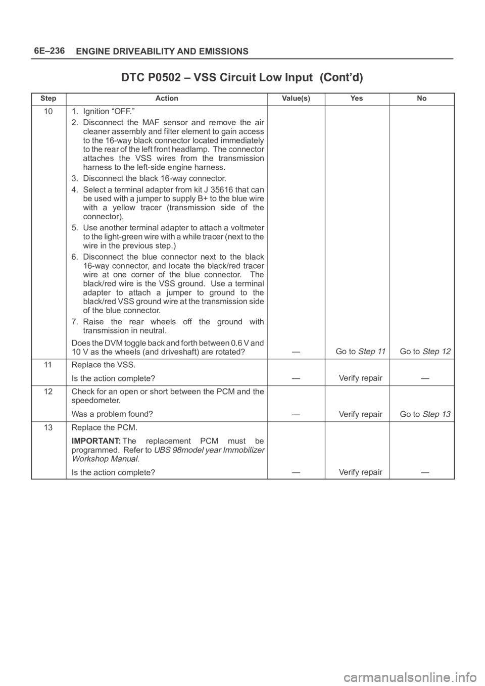
DTC P0502 – VSS Circuit Low Input
StepNo Ye s Va l u e ( s ) Action
101. Ignition “OFF.”
2. Disconnect the MAF sensor and remove the air
cleaner assembly and filter element to gain access
to the 16-way black connector located immediately
to the rear of the left front headlamp. The connector
attaches the VSS wires from the transmission
harness to the left-side engine harness.
3. Disconnect the black 16-way connector.
4. Select a terminal adapter from kit J 35616 that can
be used with a jumper to supply B+ to the blue wire
with a yellow tracer (transmission side of the
connector).
5. Use another terminal adapter to attach a voltmeter
to the light-green wire with a w h i l e t r a c e r ( n e x t t o t h e
wire in the previous step.)
6. Disconnect the blue connector next to the black
16-way connector, and locate the black/red tracer
wire at one corner of the blue connector. The
black/red wire is the VSS ground. Use a terminal
adapter to attach a jumper to ground to the
black/red VSS ground wire at the transmission side
of the blue connector.
7. Raise the rear wheels off the ground with
transmission in neutral.
Does the DVM toggle back and forth between 0.6 V and
10 V as the wheels (and driveshaft) are rotated?
—Go to Step 11Go to Step 12
11Replace the VSS.
Is the action complete?
—Verify repair—
12Check for an open or short between the PCM and the
speedometer.
Was a problem found?
—Verify repairGo to Step 13
13Replace the PCM.
IMPORTANT:The replacement PCM must be
programmed. Refer to
UBS 98model year Immobilizer
Workshop Manual.
Is the action complete?—Verify repair—
Page 4957 of 6000
6E–300
ENGINE DRIVEABILITY AND EMISSIONS
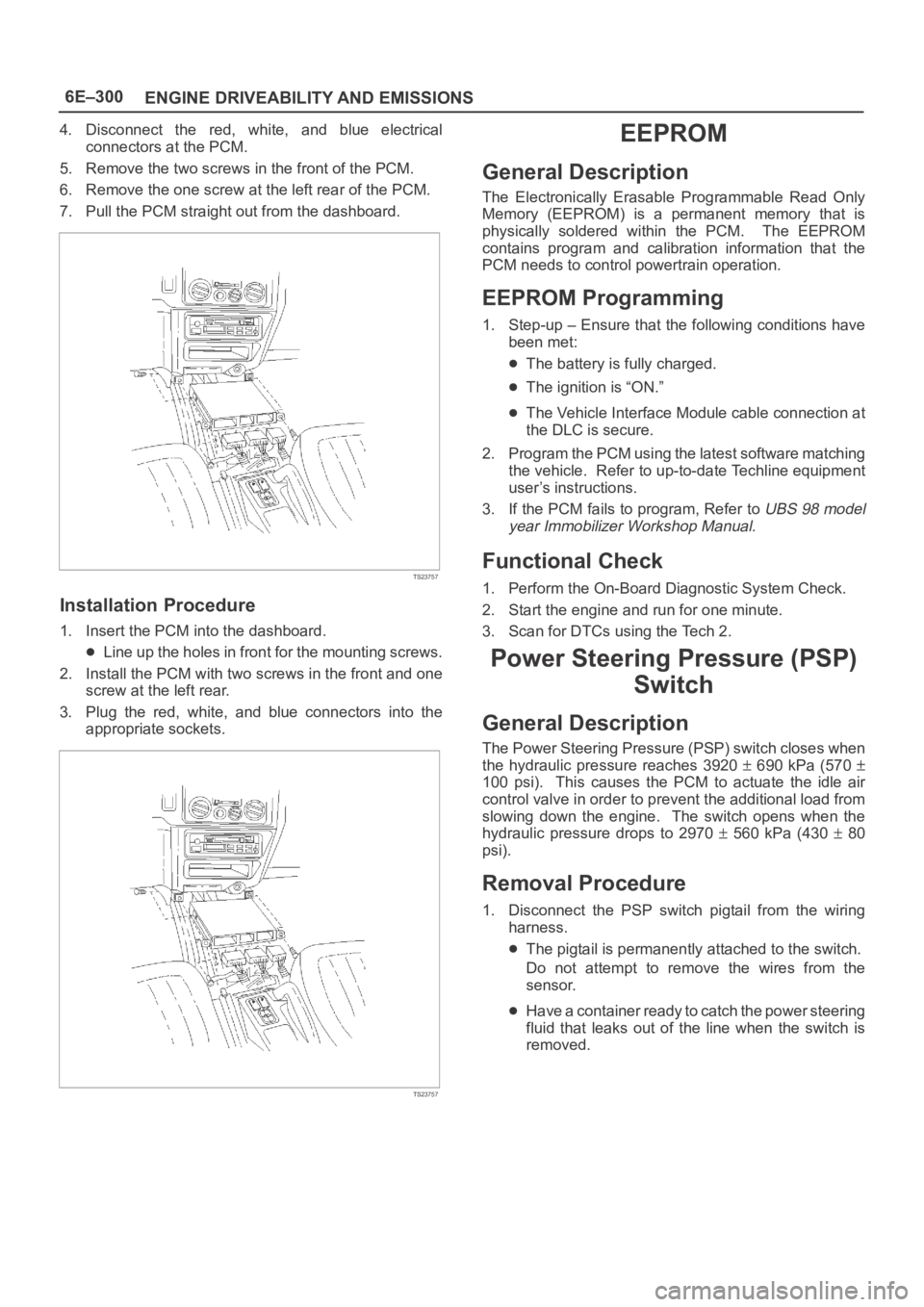
4. Disconnect the red, white, and blue electrical
connectors at the PCM.
5. Remove the two screws in the front of the PCM.
6. Remove the one screw at the left rear of the PCM.
7. Pull the PCM straight out from the dashboard.
TS23757
Installation Procedure
1. Insert the PCM into the dashboard.
Line up the holes in front for the mounting screws.
2. Install the PCM with two screws in the front and one
screw at the left rear.
3. Plug the red, white, and blue connectors into the
appropriate sockets.
TS23757
EEPROM
General Description
The Electronically Erasable Programmable Read Only
Memory (EEPROM) is a permanent memory that is
physically soldered within the PCM. The EEPROM
contains program and calibration information that the
PCM needs to control powertrain operation.
EEPROM Programming
1. Step-up – Ensure that the following conditions have
been met:
The battery is fully charged.
The ignition is “ON.”
The Vehicle Interface Module cable connection at
the DLC is secure.
2. Program the PCM using the latest software matching
the vehicle. Refer to up-to-date Techline equipment
user’s instructions.
3. If the PCM fails to program, Refer to
UBS 98 model
year Immobilizer Workshop Manual.
Functional Check
1. Perform the On-Board Diagnostic System Check.
2. Start the engine and run for one minute.
3. Scan for DTCs using the Tech 2.
Power Steering Pressure (PSP)
Switch
General Description
The Power Steering Pressure (PSP) switch closes when
the hydraulic pressure reaches 3920
690 kPa (570
100 psi). This causes the PCM to actuate the idle air
control valve in order to prevent the additional load from
slowing down the engine. The switch opens when the
hydraulic pressure drops to 2970
560 kPa (430 80
psi).
Removal Procedure
1. Disconnect the PSP switch pigtail from the wiring
harness.
The pigtail is permanently attached to the switch.
Do not attempt to remove the wires from the
sensor.
Have a container ready to catch the power steering
fluid that leaks out of the line when the switch is
removed.
Page 5119 of 6000
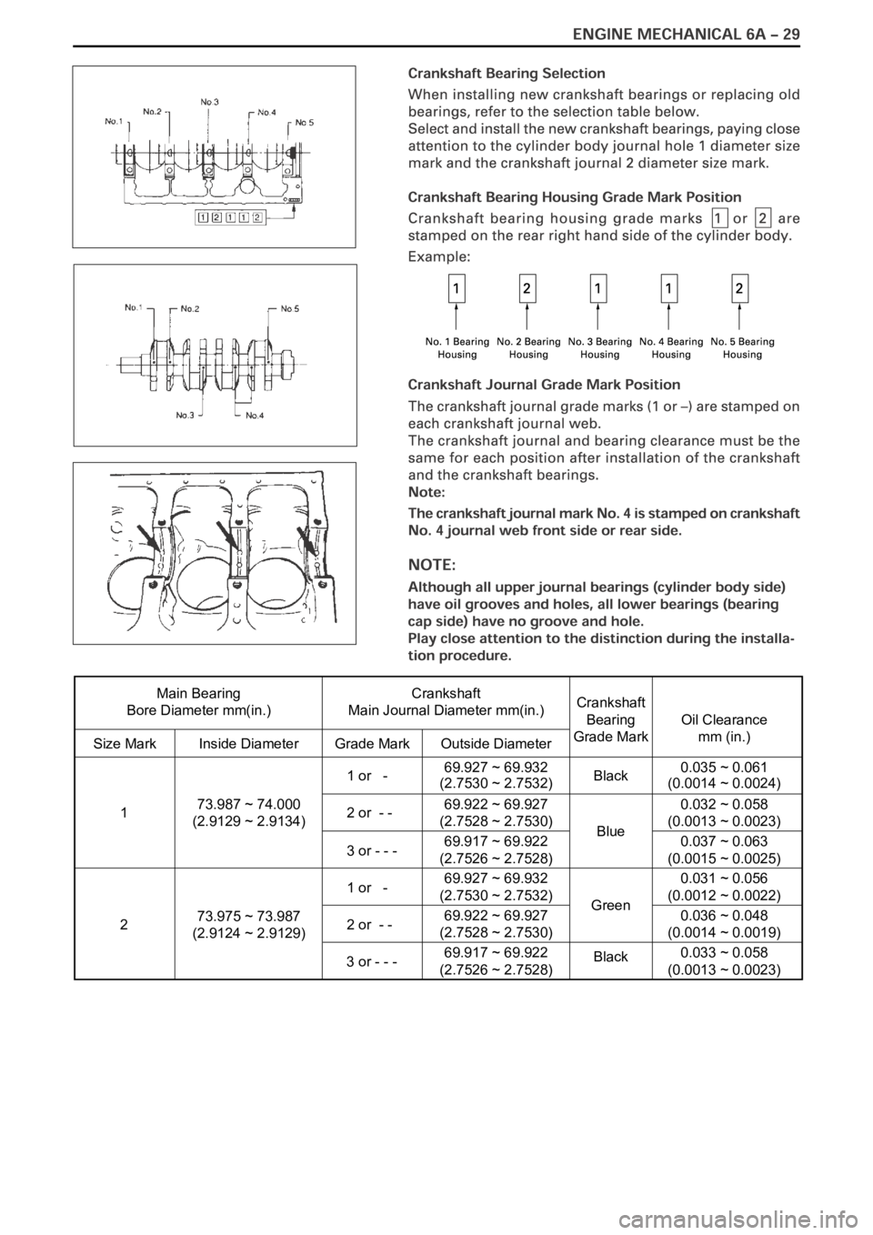
Main Bearing
Bore Diameter mm(in.)Crankshaft
Main Journal Diameter mm(in.)
Size Mark Inside DiameterGrade Mark Outside Diameter
Crankshaft
Bearing
Grade Mark
Oil Clearance
mm (in.)
1 or - 69.927 ~ 69.932
(2.7530 ~ 2.7532)
2 or - -69.922 ~ 69.927
(2.7528 ~ 2.7530)
3 or - - -69.917 ~ 69.922
(2.7526 ~ 2.7528)
1 or -69.927 ~ 69.932
(2.7530 ~ 2.7532)
2 or - - 69.922 ~ 69.927
(2.7528 ~ 2.7530)
3 or - - -69.917 ~ 69.922
(2.7526 ~ 2.7528)Black
Blue
Green
Black 73.987 ~ 74.000
(2.9129 ~ 2.9134)
73.975 ~ 73.987
(2.9124 ~ 2.9129) 1
20.035 ~ 0.061
(0.0014 ~ 0.0024)
0.032 ~ 0.058
(0.0013 ~ 0.0023)
0.037 ~ 0.063
(0.0015 ~ 0.0025)
0.031 ~ 0.056
(0.0012 ~ 0.0022)
0.036 ~ 0.048
(0.0014 ~ 0.0019)
0.033 ~ 0.058
(0.0013 ~ 0.0023)
Page 5404 of 6000
ENGINE ELECTRICAL 6D – 1
ENGINE ELECTRICAL
CONTENTS
Battery . . . . . . . . . . . . . . . . . . . . . . . . . . . . 6D–1
General Description . . . . . . . . . . . . . . . . 6D–1
Diagnosis . . . . . . . . . . . . . . . . . . . . . . . . 6D–1
On Vehicle Service . . . . . . . . . . . . . . . . . 6D–3
Main Data and Specification . . . . . . . . . . 6D–4
Starting System . . . . . . . . . . . . . . . . . . . . . 6D–5
General Description . . . . . . . . . . . . . . . . 6D–5
On Vehicle Service . . . . . . . . . . . . . . . . . 6D–7
Starter . . . . . . . . . . . . . . . . . . . . . . . . . . 6D–7
Unit Repair . . . . . . . . . . . . . . . . . . . . . . . 6D–8Charging System . . . . . . . . . . . . . . . . . . . . 6D–15
General Description . . . . . . . . . . . . . . . . 6D–15
Diagnosis . . . . . . . . . . . . . . . . . . . . . . . . 6D–16
Unit Repair . . . . . . . . . . . . . . . . . . . . . . . 6D–17
Main Data and Specification . . . . . . . . . . 6D–22
QOS4 Preheating System . . . . . . . . . . . . . . 6D–23
General Description . . . . . . . . . . . . . . . . 6D–23
System Diagram . . . . . . . . . . . . . . . . . . . 6D–23
Inspection of QOS4 System Operation . . 6D–24
BATTERY
GENERAL DESCRIPTION
DIAGNOSIS
There are six battery fluid caps at the top of the battery.
These are covered by a paper label.
The battery is completely sealed except for the six
small vent holes at the side. These vent holes permit
the escape of small amounts of gas generated by the
battery.
This type of battery has the following advantages over
conventional batteries:1. There is no need to add water during the entire
service life of the battery.
2. The battery protects itself against overcharging.
The battery will refuse to accept an excessive
charge.
(A conventional battery will accept an excessive
charge, resulting in gassing and loss of battery
fluid.)
3. The battery is much less vulnerable to self-
discharge than a conventional type battery.
1. VISUAL INSPECTION (Step 1)
Inspect the battery for obvious physical damage, such
as a cracked or broken case, which would permit
electrolyte loss.
Replace the battery if obvious physical damage is
discovered during inspection.
Check for any other physical damage and correct it as
necessary. If not, proceed to Step 2.
2. HYDROMETER CHECK (Step 2)
There is a built-in hydrometer (Charge test indicator) at
the top of the battery. It is designed to be used during
diagnostic procedures.
Before trying to read the hydrometer, carefully clean the
upper battery surface.
If your work area is poorly lit, additional light may be
necessary to read the hydrometer.
a. BLUE RING OR DOT VISIBLE – Go to Step 4.
b. BLUE RING OR DOT NOT VISIBLE – Go to
Step 3.3. FLUID LEVEL CHECK (Step 3)
The fluid level should be between the upper level line
and lower level line on side of the battery.
a. CORRECT FLUID LEVEL – Charge the battery.
b. BELOW LOWER LEVEL – Replace battery.
4. VOLTAGE CHECK (Step 4)
(1) Put voltmeter test leads to battery terminals.
a. VOLTAGE IS 12.4V OR ABOVE – Go to Step 5.
b. VOLTAGE IS UNDER 12.4V – Go to procedure
(2) below.
(2) Determine fast charge amperage from
specification. (See Main Data and Specifications in
this section.)
Fast charge battery for 30 minutes at amperage
rate no higher than specified value.
Take voltage and amperage readings after charge.
a. VOLTAGE IS ABOVE 16V AT BELOW 1/3 OF
AMPERAGE RATE – Replace battery.
Page 5406 of 6000

ENGINE ELECTRICAL 6D – 3
ON-VEHICLE SERVICE
BATTERY CHARGING
Observe the following safety precautions when
charging the battery:
1. Never attempt to charge the battery when the fluid
level is below the lower level line on the side of the
battery. In this case, the battery must be replaced.
2. Pay close attention to the battery during the
charging procedure.
Battery charging should be discontinued or the rate
of charge reduced if the battery feels hot to the
touch.
Battery charging should be discontinued or the rate
of charge reduced if the battery begins to gas or
spew electrolyte from the vent holes.
3. In order to more easily view the hydrometer blue
dot or ring, it may be necessary to jiggle or tilt the
battery.
4. Battery temperature can have a great effect on
battery charging capacity.
5. The sealed battery used on this vehicle may be
either quick-charged or slow-charged in the same
manner as other batteries.
Whichever method you decide to use, be sure that
you completely charge the battery. Never partially
charge the battery.
JUMP STARTING
JUMP STARTING WITH AN AUXILIARY
(BOOSTER) BATTERY
CAUTION: Never push or tow the vehicle in an
attempt to start it. Serious damage to the emission
system as well as other vehicle parts will result.
Treat both the discharged battery and the booster
battery with great care when using jumper cables.
Carefully follow the jump starting procedure, being
careful at all times to avoid sparking.
WARNING: Failure to carefully follow the jump
starting procedure could result in the following:
1. Serious personal injury, particularly to your
eyes.
2. Property damage from a battery explosion,
battery acid, or an electrical fire.
3. Damage to the electronic components of one or
both vehicles.
Never expose the battery to an open flame or electrical
spark. Gas generated by the battery may catch fire or
explode. Remove any rings, watches, or other jewelry
before working around the battery. Protect your eyes by
wearing an approved set of goggles.
Never allow battery fluid to come in contact with your
eyes or skin.
Never allow battery fluid to come in contact with fabrics
or painted surfaces.
Battery fluid is a highly corrosive acid.Should battery fluid come in contact with your eyes,
skin, fabric, or a painted surface, immediately and
thoroughly rinse the affected area with clean tap water.
Never allow metal tools or jumper cables to come in
contact with the positive battery terminal, or any other
metal surface of the vehicle. This will protect against a
short circuit.
Always keep batteries out of the reach of young
children.
JUMP STARTING PROCEDURE
1. Set the vehicle parking brake.
If the vehicle is equipped with an automatic
transmission, place the selector lever in the “PARK”
position.
If the vehicle is equipped with a manual
transmission place the shift lever in the “NEUTRAL”
position.
Turn “OFF” the ignition.
Turn “OFF” all lights and any other accessory
requiring electrical power.
2. Look at the built-in hydrometer.
If the indication area of the built-in hydrometer is
completely clear, do not try to jump start.
3. Attach the end of one jumper cable to the positive
terminal of the booster battery.
Attach the other end of the same cable to the
positive terminal of the discharged battery.
Do not allow the vehicles to touch each other.
This will cause a ground connection, effectively
neutralizing the charging procedure.
Be sure that the booster battery has a 12 volt rating.
4. Attach one end of the remaining cable to the
negative terminal of the booster battery.
Attach the other end of the same cable to a solid
engine ground (such as the A/C compressor
bracket or the generator mounting bracket) of the
vehicle with the discharged battery.
This ground connection must be at least 450 mm
(18 in) from the battery of the vehicle whose battery
is being charged.
WARNING: Never attach the end of the jumper
cable directly to the negative terminal of the dead
battery.
5. Start the engine of the vehicle with the good battery.
Make sure that all unnecessary electrical
accessories have been turned “OFF”.
6. Start the engine of the vehicle with the dead battery.
7. To remove the jumper cables, follow the above
directions in the reverse order.
Be sure to first disconnect the negative cable from
the vehicle with the discharged battery.