Page 1910 of 6000
6E–17 4JX1–TC ENGINE DRIVEABILITY AND EMISSIONS
ECM Pinout Table, 32-Way Connector – J2 BLUE – Lower
060RW137
J2 – BLUE
PINSIGNAL
17COOLANT TEMP OUT
18OIL TEMPERATURE
19TDC/CAM
20SPARE ANALOG 2
21INTAKE AIR TEMPERATURE
22+5VRTN2
23BOOST/INLET PRESSURE
24+5VRTN3
25ACCELERATOR POSITION
26+5VRTN1
27EGR VACUUM PRESSURE
28INTAKE SM S2T
29DIAGNOSTIC REQUEST SW
30COOLANT TEMPERATURE
31A/T PARK SW
32CRANKSHAFT
Page 1916 of 6000
6E–23 4JX1–TC ENGINE DRIVEABILITY AND EMISSIONS
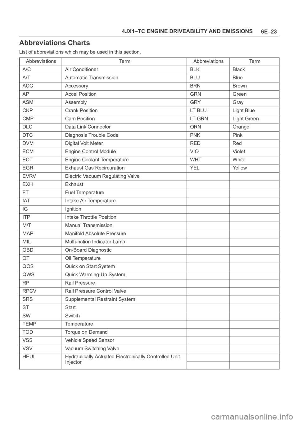
Abbreviations Charts
List of abbreviations which may be used in this section.
Abbreviations
Te r mAbbreviationsTe r m
A/CAir ConditionerBLKBlack
A/TAutomatic TransmissionBLUBlue
ACCAccessoryBRNBrown
APAccel PositionGRNGreen
ASMAssemblyGRYGray
CKPCrank PositionLT B L ULight Blue
CMPCam PositionLT G R NLight Green
DLCData Link ConnectorORNOrange
DTCDiagnosis Trouble CodePNKPink
DVMDigital Volt MeterREDRed
ECMEngine Control ModuleVIOViolet
ECTEngine Coolant TemperatureWHTWhite
EGRExhaust Gas RecircurationYELYe l l o w
EVRVElectric Vacuum Regulating Valve
EXHExhaust
FTFuel Temperature
IATIntake Air Temperature
IGIgnition
ITPIntake Throttle Position
M/TManual Transmission
MAPManifold Absolute Pressure
MILMulfunction Indicator Lamp
OBDOn-Board Diagnostic
OTOil Temperature
QOSQuick on Start System
QWSQuick Warming-Up System
RPRail Pressure
RPCVRail Pressure Control Valve
SRSSupplemental Restraint System
STStart
SWSwitch
TEMPTemperature
TODTorque on Demand
VSSVehicle Speed Sensor
VSVVacuum Switching Valve
HEUIHydraulically Actuated Electronically Controlled Unit
InjectorInjector
Page 1950 of 6000
6E–57 4JX1–TC ENGINE DRIVEABILITY AND EMISSIONS
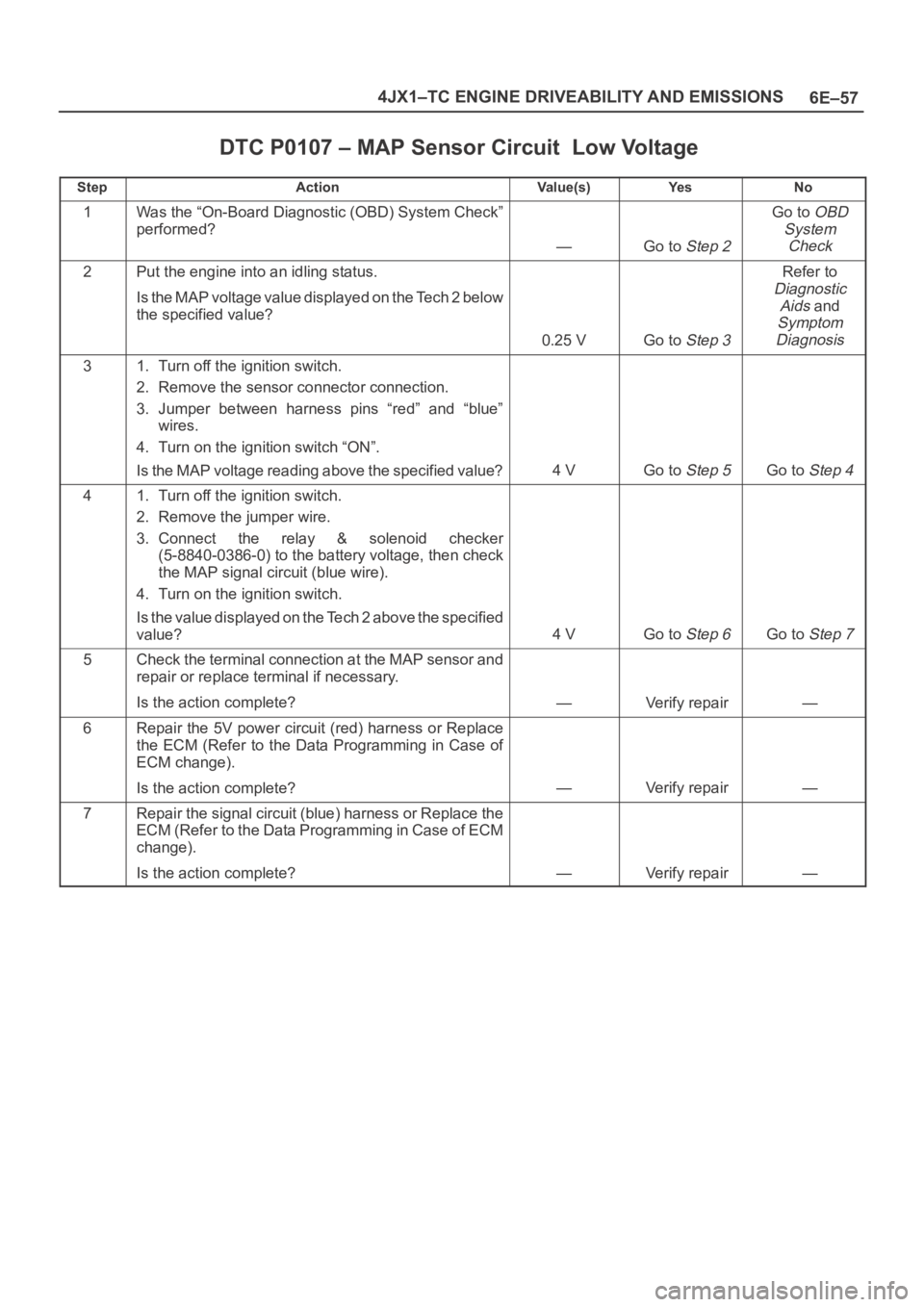
DTC P0107 – MAP Sensor Circuit Low Voltage
StepActionVa l u e ( s )Ye sNo
1Was the “On-Board Diagnostic (OBD) System Check”
performed?
—Go to Step 2
Go to OBD
System
Check
2Put the engine into an idling status.
Is the MAP voltage value displayed on the Tech 2 below
the specified value?
0.25 VGo to Step 3
Refer to
Diagnostic
Aids
and
Symptom
Diagnosis
31. Turn off the ignition switch.
2. Remove the sensor connector connection.
3. Jumper between harness pins “red” and “blue”
wires.
4. Turn on the ignition switch “ON”.
Is the MAP voltage reading above the specified value?
4 VGo to Step 5Go to Step 4
41. Turn off the ignition switch.
2. Remove the jumper wire.
3. Connect the relay & solenoid checker
(5-8840-0386-0) to the battery voltage, then check
the MAP signal circuit (blue wire).
4. Turn on the ignition switch.
Is the value displayed on the Tech 2 above the specified
value?
4 VGo to Step 6Go to Step 7
5Check the terminal connection at the MAP sensor and
repair or replace terminal if necessary.
Is the action complete?
—Verify repair—
6Repair the 5V power circuit (red) harness or Replace
the ECM (Refer to the Data Programming in Case of
ECM change).
Is the action complete?
—Verify repair—
7Repair the signal circuit (blue) harness or Replace the
ECM (Refer to the Data Programming in Case of ECM
change).
Is the action complete?
—Verify repair—
Page 2028 of 6000
6E–135 4JX1–TC ENGINE DRIVEABILITY AND EMISSIONS
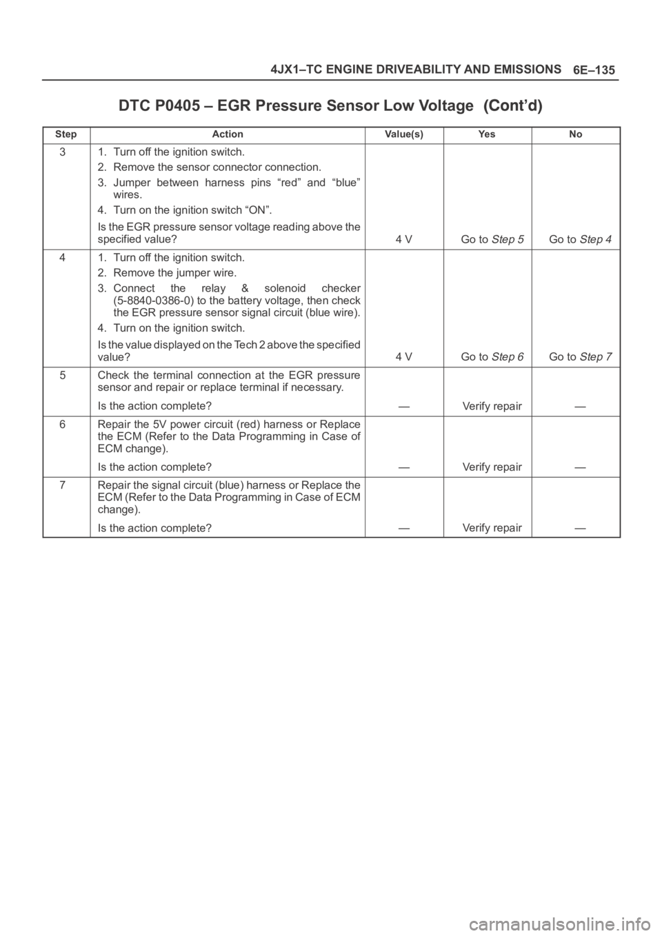
DTC P0405 – EGR Pressure Sensor Low Voltage
StepNo Ye s Va l u e ( s ) Action
31. Turn off the ignition switch.
2. Remove the sensor connector connection.
3. Jumper between harness pins “red” and “blue”
wires.
4. Turn on the ignition switch “ON”.
Is the EGR pressure sensor voltage reading above the
specified value?
4 VGo to Step 5Go to Step 4
41. Turn off the ignition switch.
2. Remove the jumper wire.
3. Connect the relay & solenoid checker
(5-8840-0386-0) to the battery voltage, then check
the EGR pressure sensor signal circuit (blue wire).
4. Turn on the ignition switch.
Is the value displayed on the Tech 2 above the specified
value?
4 VGo to Step 6Go to Step 7
5Check the terminal connection at the EGR pressure
sensor and repair or replace terminal if necessary.
Is the action complete?
—Verify repair—
6Repair the 5V power circuit (red) harness or Replace
the ECM (Refer to the Data Programming in Case of
ECM change).
Is the action complete?
—Verify repair—
7Repair the signal circuit (blue) harness or Replace the
ECM (Refer to the Data Programming in Case of ECM
change).
Is the action complete?
—Verify repair—
Page 2046 of 6000
6E–153 4JX1–TC ENGINE DRIVEABILITY AND EMISSIONS
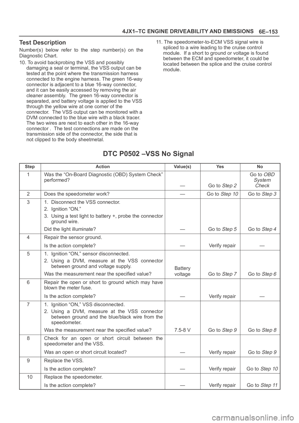
Test Description
Number(s) below refer to the step number(s) on the
Diagnostic Chart.
10. To avoid backprobing the VSS and possibly
damaging a seal or terminal, the VSS output can be
tested at the point where the transmission harness
connected to the engine harness. The green 16-way
connector is adjacent to a blue 16-way connector,
and it can be easily accessed by removing the air
cleaner assembly. The green 16-way connector is
separated, and battery voltage is applied to the VSS
through the yellow wire at one corner of the
connector. The VSS output can be monitored with a
DVM connected to the blue wire with a black tracer.
The two wires are next to each other in the 16-way
connector . The test connections are made on the
transmission side of the connector, the side that is
not clipped to the body sheetmetal.11. The speedometer-to-ECM VSS signal wire is
spliced to a wire leading to the cruise control
module. If a short to ground or voltage is found
between the ECM and speedometer, it could be
located between the splice and the cruise control
module.
DTC P0502 –VSS No Signal
StepActionVa l u e ( s )Ye sNo
1Was the “On-Board Diagnostic (OBD) System Check”
performed?
—Go to Step 2
Go to OBD
System
Check
2Does the speedometer work?—Go to Step 10Go to Step 3
31. Disconnect the VSS connector.
2. Ignition “ON.”
3. Using a test light to battery +, probe the connector
ground wire.
Did the light illuminate?
—Go to Step 5Go to Step 4
4Repair the sensor ground.
Is the action complete?
—Verify repair—
51. Ignition “ON,” sensor disconnected.
2. Using a DVM, measure at the VSS connector
between ground and voltage supply.
Was the measurement near the specified value?
Battery
voltage
Go to Step 7Go to Step 6
6Repair the open or short to ground which may have
blown the meter fuse.
Is the action complete?
—Verify repair—
71. Ignition “ON,” VSS disconnected.
2. Using a DVM, measure at the VSS connector
between ground and the blue/black wire from the
speedometer.
Was the measurement near the specified value?
7.5-8 VGo to Step 9Go to Step 8
8Check for an open or short circuit between the
speedometer and the VSS.
Was an open or short circuit located?
—Verify repairGo to Step 9
9Replace the VSS.
Is the action complete?
—Verify repairGo to Step 10
10Replace the speedometer.
Is the action complete?
—Verify repairGo to Step 11
Page 2204 of 6000
7A–50
AUTOMATIC TRANSMISSION (4L30–E)
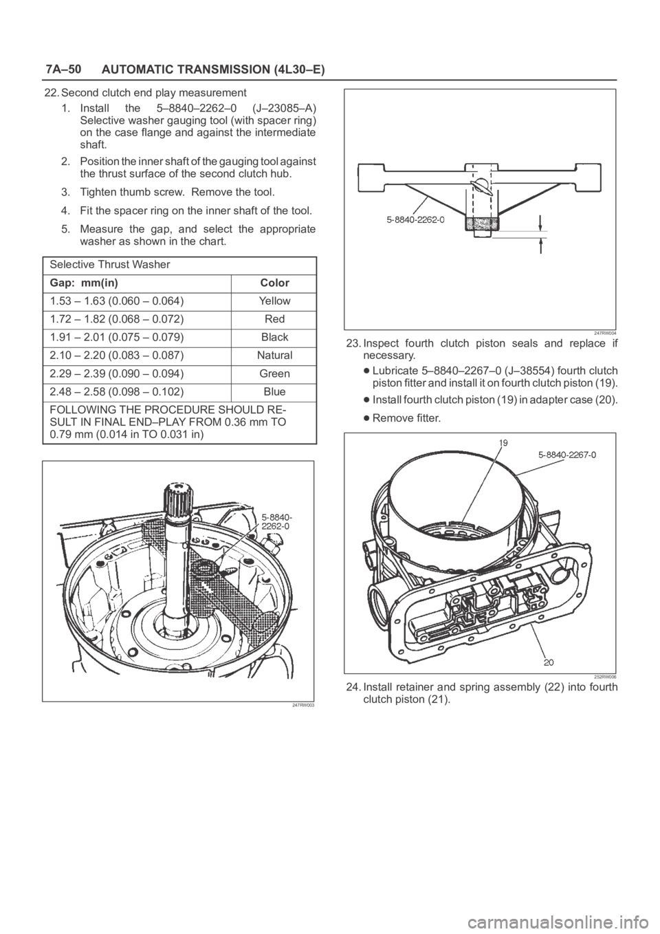
22. Second clutch end play measurement
1. Install the 5–8840–2262–0 (J–23085–A)
Selective washer gauging tool (with spacer ring)
on the case flange and against the intermediate
shaft.
2. Position the inner shaft of the gauging tool against
the thrust surface of the second clutch hub.
3. Tighten thumb screw. Remove the tool.
4. Fit the spacer ring on the inner shaft of the tool.
5. Measure the gap, and select the appropriate
washer as shown in the chart.
Selective Thrust Washer
Gap: mm(in)Color
1.53 – 1.63 (0.060 – 0.064)Yellow
1.72 – 1.82 (0.068 – 0.072)Red
1.91 – 2.01 (0.075 – 0.079)Black
2.10 – 2.20 (0.083 – 0.087)Natural
2.29 – 2.39 (0.090 – 0.094)Green
2.48 – 2.58 (0.098 – 0.102)Blue
FOLLOWING THE PROCEDURE SHOULD RE-
SULT IN FINAL END–PLAY FROM 0.36 mm TO
0.79 mm (0.014 in TO 0.031 in)
247RW003
247RW004
23. Inspect fourth clutch piston seals and replace if
necessary.
Lubricate 5–8840–2267–0 (J–38554) fourth clutch
piston fitter and install it on fourth clutch piston (19).
Install fourth clutch piston (19) in adapter case (20).
Remove fitter.
252RW006
24. Install retainer and spring assembly (22) into fourth
clutch piston (21).
Page 2206 of 6000
7A–52
AUTOMATIC TRANSMISSION (4L30–E)
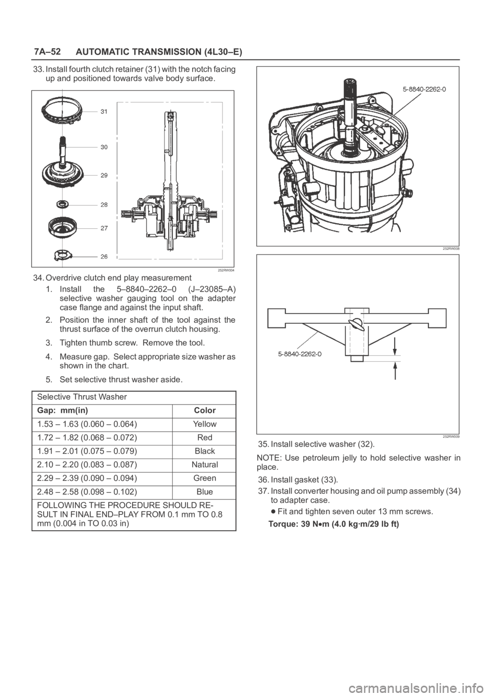
33. Install fourth clutch retainer (31) with the notch facing
up and positioned towards valve body surface.
252RW004
34. Overdrive clutch end play measurement
1. Install the 5–8840–2262–0 (J–23085–A)
selective washer gauging tool on the adapter
case flange and against the input shaft.
2. Position the inner shaft of the tool against the
thrust surface of the overrun clutch housing.
3. Tighten thumb screw. Remove the tool.
4. Measure gap. Select appropriate size washer as
shown in the chart.
5. Set selective thrust washer aside.
Selective Thrust Washer
Gap: mm(in)Color
1.53 – 1.63 (0.060 – 0.064)Yellow
1.72 – 1.82 (0.068 – 0.072)Red
1.91 – 2.01 (0.075 – 0.079)Black
2.10 – 2.20 (0.083 – 0.087)Natural
2.29 – 2.39 (0.090 – 0.094)Green
2.48 – 2.58 (0.098 – 0.102)Blue
FOLLOWING THE PROCEDURE SHOULD RE-
SULT IN FINAL END–PLAY FROM 0.1 mm TO 0.8
mm (0.004 in TO 0.03 in)
252RW008
252RW009
35. Install selective washer (32).
NOTE: Use petroleum jelly to hold selective washer in
place.
36. Install gasket (33).
37. Install converter housing and oil pump assembly (34)
to adapter case.
Fit and tighten seven outer 13 mm screws.
To r q u e : 3 9 N
m (4.0 kgꞏm/29 lb ft)
Page 2273 of 6000
7A1–28
TRANSMISSION CONTROL SYSTEM (4L30–E)
DTC P0560 System Voltage Malfunction
StepActionYe sNo
11. Install the scan tool.
2. With the engine “off”, turn the ignition switch “on”.
NOTE: Before clearing DTC(s), use the scan tool to record “Failure
Records” for reference, as data will be lost when the “Clear Info”
function is used.
3. Record the DTC “Failure Records”. Note: If any other DTCs
are present, refer to their applicable diagnostic charts before
continuing.
4. Using the J–39200 DVOM, measure the battery voltage
across the battery terminals. Record the measurement for
future reference.
Is the voltage higher than 10.5 volts?
Go to Step 2
Go to Engine
Electrical in
Engine section
2Start the engine and warm to normal operating temperature.
Is the generator/check engine light “on”?Go to Starting
and Charging
System in Engine
section
Go to Step 3
31. Increase the engine speed to 1,000–1,500 rpm.
2. Observe scan tool system voltage.
Is the system voltage within 13–15 volts.
Go to Step 4
Go to Starting
and Charging
System in Engine
section
41. Turn the ignition switch “off”.
2. Disconnect the J1(RED) and J3 (BLUE) PCM connector
(additional DTCs will set).
3. With the engine “off”, turn the ignition switch “on”.
4. Using the J39200 DVOM, measure the battery voltage input at
PCM connector terminals J1–A4 and J3–E16.
Is there a voltage variance between the voltage measured at the
battery (taken in Step 1) and at terminals J1–A4 and J3–E16 that
is greater than 0.5 volts?
Go to Step 5Go to Step 6
5Repair the high resistance condition in circuit WHT.
Was the circuit repaired?
Go to Step 10—
61. Disconnect the J3 (BLUE) PCM connector.
2. Measure the ignition voltage input at PCM connector terminals
J3–E16 and J3–F16.
Is there a voltage variance between the voltage measured at the
battery (taken in Step 1) and at terminals J3–E16 and J3–F16 that
is greater than 0.5 volts?
Go to Step 7Go to Step 8
7Repair the high resistance condition is circuit RED/BLU.
Was the circuit repaired?
Go to Step 10—
8Check PCM connector terminals J1–A4, J3–E16 and J3–F16 for
bent, damaged, or backed out connector pins. Also check for
weak terminal tension.
Was a problem found?
Go to Step 10Go to Step 9