Page 4630 of 6000
6D2–5
IGNITION SYSTEM
Crankshaft Angle Sensor
Removal
1. Disconnect battery ground cable
2. Wiring connector from crankshaft angle sensor.
3. Remove crankshaft angle sensor from cylinder block.
012RS008
Installation
1. Install crankshaft angle sensor into the cylinder block.
Before installation,apply small amount of engine oil to
the O–ring.
Torque: 10 Nꞏm (1.0 Kgꞏm/89 lb in)
2. Reconnect wiring connector to crankshaft angle
sensor.
Page 4633 of 6000
6D3–2STARTING AND CHARGING SYSTEM
Starting System
General Description
Cranking Circuit
The cranking system consists of a battery, starter, starter
switch, starter relay, etc. These main components are
connected.
Starter
The cranking system employs a magnetic type reduction
starter in which the motor shaft is also used as a pinion
shaft. When the starter switch is turned on, the contacts of
magnetic switch are closed, and the armature rotates. At
the same time, the plunger is attracted, and the pinion is
pushed forward by the shift lever to mesh with the ring
gear.
Then, the ring gear runs to start the engine. When the
engine starts and the starter switch is turned off, the
plunger returns, the pinion is disengaged from the ring
gear, and the armature stops rotation. When the engine
speed is higher than the pinion, the pinion idles, so that
the armature is not driven.
Page 4635 of 6000
6D3–4STARTING AND CHARGING SYSTEM
Diagnosis
ConditionPossible causeCorrection
Starter does not runCharging failureRepair charging system
Battery FailureReplace Battery
Terminal connection failureRepair or replace terminal connector
and/or wiring harness
Starter switch failureRepair or replace starter switch
Starter failureRepair or replace starter
Page 4636 of 6000
6D3–5 STARTING AND CHARGING SYSTEM
Starter
Removal
1. Battery ground cable.
2. Remove exhaust front left pipe(1).
150RW062
3. Remove heat protector(3).
4. Disconnect starter wiring connector from terminals
“B” and “S”(4).
5. Remove starter assembly mounting bolts on inside
and outside(5).
6. Remove starter assembly toward the bottom of
engine(6).
065RW027
Installation
1. Install starter assembly(6).2. Install mounting bolts and tighten bolts to specified
torque(5).
Torque: 40 Nꞏm (4.1 Kgꞏm/30 lb ft)
3. Reconnect the connectors to terminals “B” and “S”
and tighten Terminals “B” to specified torque.
Torque: 9 Nꞏm (0.9 Kgꞏm/80 lb in)
4. Install heat protector(3).
065RW027
5. Install exhaust front left pipe and tighten bolts and
nuts to specified torque(2).
Stud Nuts
Torque: 67 Nꞏm (6.8 Kgꞏm/49 lb ft)
Nuts
Torque: 43 Nꞏm (4.4 Kgꞏm/32 lb ft)
150RW062
6. Reconnect the battery ground cable.
Page 4644 of 6000

6D3–13 STARTING AND CHARGING SYSTEM
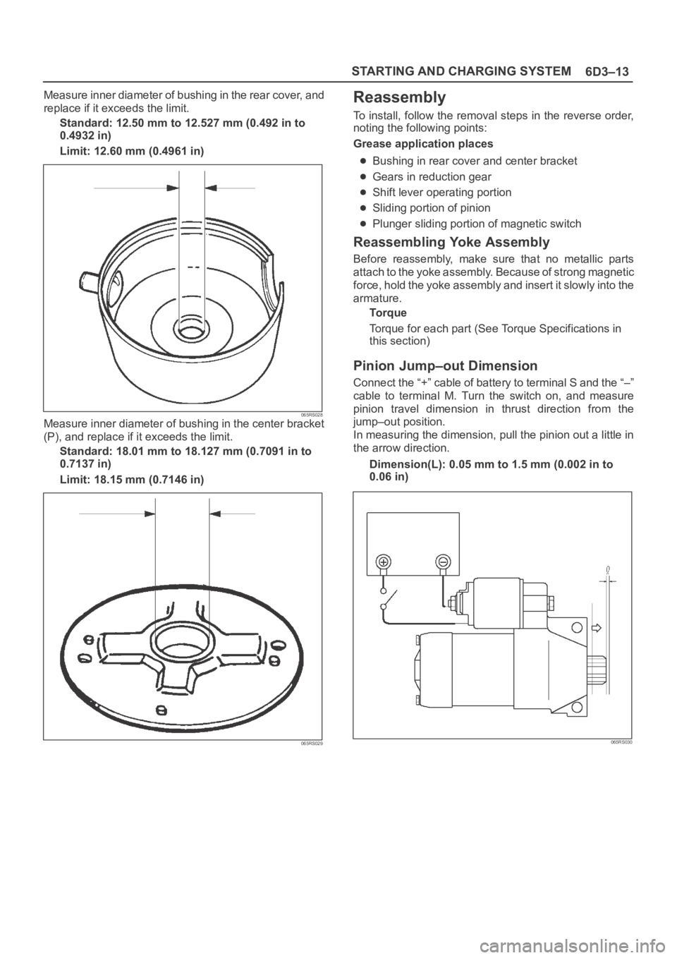
Measure inner diameter of bushing in the rear cover, and
replace if it exceeds the limit.
Standard: 12.50 mm to 12.527 mm (0.492 in to
0.4932 in)
Limit: 12.60 mm (0.4961 in)
065RS028Measure inner diameter of bushing in the center bracket
(P), and replace if it exceeds the limit.
Standard: 18.01 mm to 18.127 mm (0.7091 in to
0.7137 in)
Limit: 18.15 mm (0.7146 in)
065RS029
Reassembly
To install, follow the removal steps in the reverse order,
noting the following points:
Grease application places
Bushing in rear cover and center bracket
Gears in reduction gear
Shift lever operating portion
Sliding portion of pinion
Plunger sliding portion of magnetic switch
Reassembling Yoke Assembly
Before reassembly, make sure that no metallic parts
attach to the yoke assembly. Because of strong magnetic
force, hold the yoke assembly and insert it slowly into the
armature.
To r q u e
Torque for each part (See Torque Specifications in
this section)
Pinion Jump–out Dimension
Connect the “+” cable of battery to terminal S and the “–”
cable to terminal M. Turn the switch on, and measure
pinion travel dimension in thrust direction from the
jump–out position.
In measuring the dimension, pull the pinion out a little in
the arrow direction.
Dimension(L): 0.05 mm to 1.5 mm (0.002 in to
0.06 in)
065RS030
Page 4645 of 6000
6D3–14STARTING AND CHARGING SYSTEM
If the measured value is out of standard, insert dust cover,
or disassemble and adjust.
065RW019
Characteristic Test
For easily confirming the characteristics, conduct the no
load test as follows:
Rating as short as 30 seconds requires rapid testing.
Fix the starter on the test bench, and wire as shown in
illustration. When the switch is closed, the current flows
and the starter runs under no load. At this time, measure
current, voltage and speed to check if they satisfy the
standard.
065RW020
Legend
(1) Volt Meter
(2) Tachometer
(3) Battery
(4) Ammeter
(5) Switch
Page 4649 of 6000

6D3–18STARTING AND CHARGING SYSTEM
Charging System
General Description
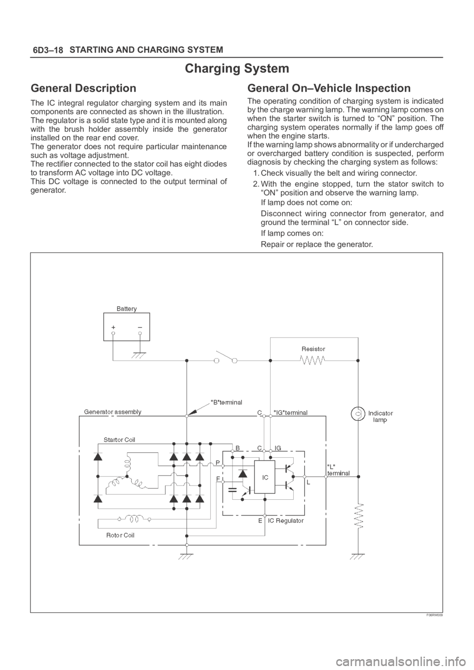
The IC integral regulator charging system and its main
components are connected as shown in the illustration.
The regulator is a solid state type and it is mounted along
with the brush holder assembly inside the generator
installed on the rear end cover.
The generator does not require particular maintenance
such as voltage adjustment.
The rectifier connected to the stator coil has eight diodes
to transform AC voltage into DC voltage.
This DC voltage is connected to the output terminal of
generator.
General On–Vehicle Inspection
The operating condition of charging system is indicated
by the charge warning lamp. The warning lamp comes on
when the starter switch is turned to “ON” position. The
charging system operates normally if the lamp goes off
when the engine starts.
If the warning lamp shows abnormality or if undercharged
or overcharged battery condition is suspected, perform
diagnosis by checking the charging system as follows:
1. Check visually the belt and wiring connector.
2. With the engine stopped, turn the stator switch to
“ON” position and observe the warning lamp.
If lamp does not come on:
Disconnect wiring connector from generator, and
ground the terminal “L” on connector side.
If lamp comes on:
Repair or replace the generator.
F06RW009
Page 4650 of 6000

6D3–19 STARTING AND CHARGING SYSTEM
Generator
Removal
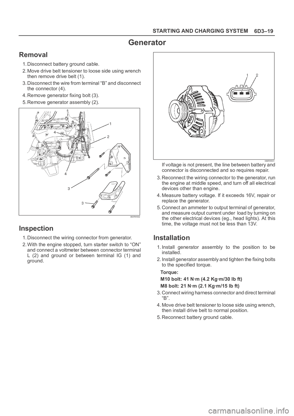
1. Disconnect battery ground cable.
2. Move drive belt tensioner to loose side using wrench
then remove drive belt (1).
3. Disconnect the wire from terminal “B” and disconnect
the connector (4).
4. Remove generator fixing bolt (3).
5. Remove generator assembly (2).
060RW002
Inspection
1. Disconnect the wiring connector from generator.
2. With the engine stopped, turn starter switch to “ON”
and connect a voltmeter between connector terminal
L (2) and ground or between terminal IG (1) and
ground.
066RW001If voltage is not present, the line between battery and
connector is disconnected and so requires repair.
3. Reconnect the wiring connector to the generator, run
the engine at middle speed, and turn off all electrical
devices other than engine.
4. Measure battery voltage. If it exceeds 16V, repair or
replace the generator.
5. Connect an ammeter to output terminal of generator,
and measure output current under load by turning on
the other electrical devices (eg., head lights). At this
time, the voltage must not be less than 13V.
Installation
1. Install generator assembly to the position to be
installed.
2. Install generator assembly and tighten the fixing bolts
to the specified torque.
To r q u e :
M10 bolt: 41 Nꞏm (4.2 Kgꞏm/30 lb ft)
M8 bolt: 21 Nꞏm (2.1 Kgꞏm/15 lb ft)
3. Connect wiring harness connector and direct terminal
“B”.
4. Move drive belt tensioner to loose side using wrench,
then install drive belt to normal position.
5. Reconnect battery ground cable.