1998 OPEL FRONTERA wheel bolts
[x] Cancel search: wheel boltsPage 3478 of 6000
SUPPLEMENTAL RESTRAINT SYSTEM9J–41
Installation
1. Install the combination switch assembly with SRS
coil.
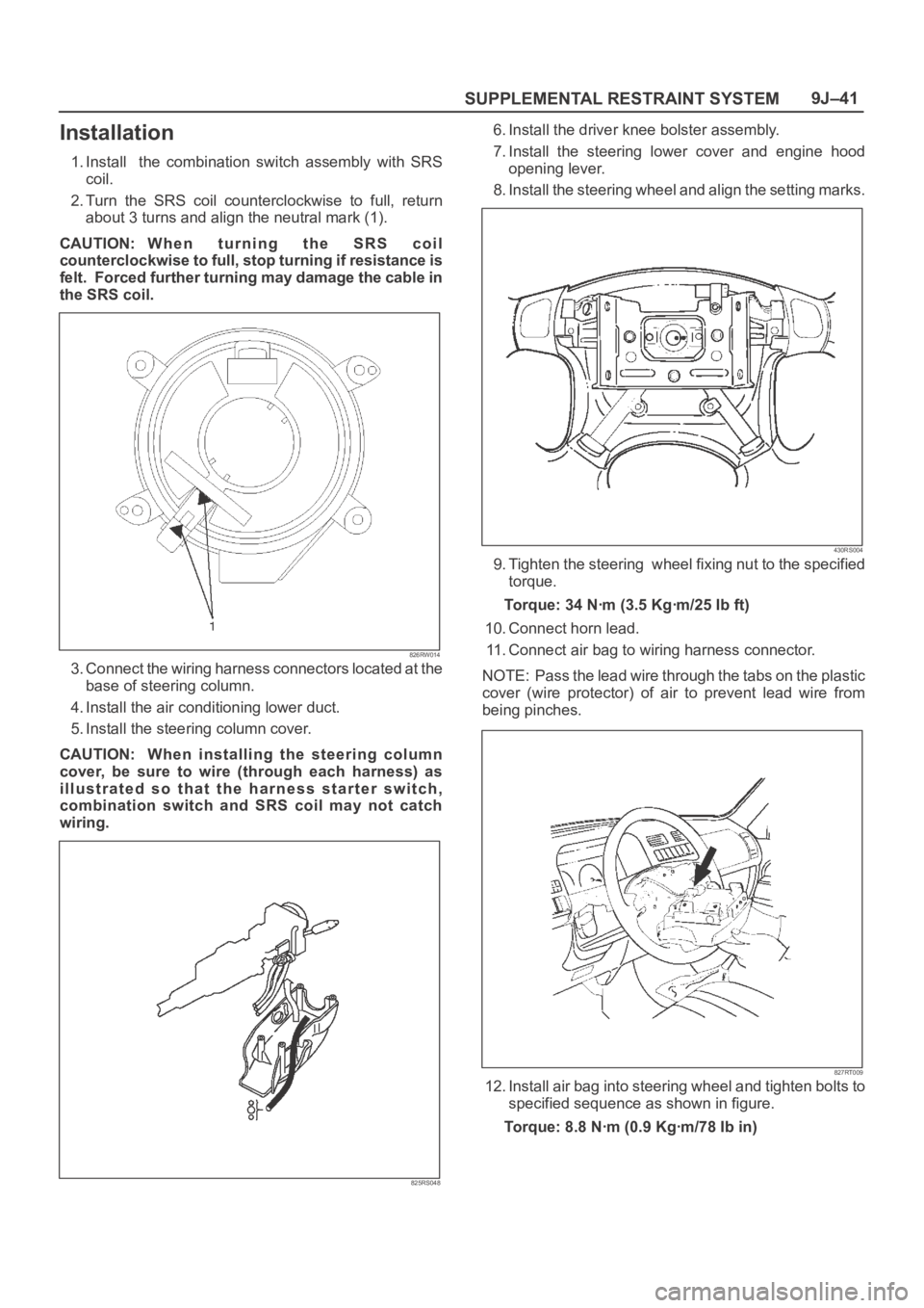
2. Turn the SRS coil counterclockwise to full, return
about 3 turns and align the neutral mark (1).
CAUTION: W h e n t u r n i n g t h e S R S c o i l
counterclockwise to full, stop turning if resistance is
felt. Forced further turning may damage the cable in
the SRS coil.
826RW014
3. Connect the wiring harness connectors located at the
base of steering column.
4. Install the air conditioning lower duct.
5. Install the steering column cover.
CAUTION: When installing the steering column
cover, be sure to wire (through each harness) as
illustrated so that the harness starter switch,
combination switch and SRS coil may not catch
wiring.
825RS048
6. Install the driver knee bolster assembly.
7. Install the steering lower cover and engine hood
opening lever.
8. Install the steering wheel and align the setting marks.
430RS004
9. Tighten the steering wheel fixing nut to the specified
torque.
Torque: 34 Nꞏm (3.5 Kgꞏm/25 Ib ft)
10. Connect horn lead.
11. Connect air bag to wiring harness connector.
NOTE: Pass the lead wire through the tabs on the plastic
cover (wire protector) of air to prevent lead wire from
being pinches.
827RT009
12. Install air bag into steering wheel and tighten bolts to
specified sequence as shown in figure.
Torque: 8.8 Nꞏm (0.9 Kgꞏm/78 Ib in)
Page 3481 of 6000
SUPPLEMENTAL RESTRAINT SYSTEM 9J–44
Installation
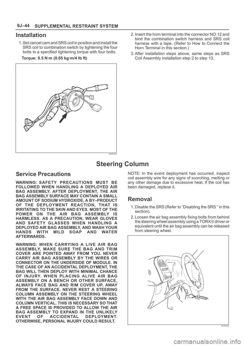
1. Set cancel cam and SRS coil in position and install the
SRS coil to combination switch by tightening the four
bolts to a specified tightening torque with four bolts.
Torque: 0.5 Nꞏm (0.05 kgꞏm/4 Ib ft)
825RX033
2. Insert the horn terminal into the connector NO.12 and
bind the combination switch harness and SRS coil
harness with a tape. (Refer to How to Connect the
Horn Terminal in this section.)
3. After installation steps above, same steps as SRS
Coil Assembly installation step 2 to step 13.
Steering Column
Service Precautions
WARNING: SAFETY PRECAUTIONS MUST BE
FOLLOWED WHEN HANDLING A DEPLOYED AIR
BAG ASSEMBLY. AFTER DEPLOYMENT, THE AIR
BAG ASSEMBLY SURFACE MAY CONTAIN A SMALL
AMOUNT OF SODIUM HYDROXIDE, A BY–PRODUCT
OF THE DEPLOYMENT REACTION, THAT IS
IRRITATING TO THE SKIN AND EYES. MOST OF THE
POWER ON THE AIR BAG ASSEMBLY IS
HARMLESS. AS A PRECAUTION, WEAR GLOVES
AND SAFETY GLASSES WHEN HANDLING A
DEPLOYED AIR BAG ASSEMBLY, AND WASH YOUR
HANDS WITH MILD SOAP AND WATER
AFTERWARDS.
WARNING: WHEN CARRYING A LIVE AIR BAG
ASSEMBLY, MAKE SURE THE BAG AND TRIM
COVER ARE POINTED AWAY FROM YOU. NEVER
CARRY AIR BAG ASSEMBLY BY THE WIRES OR
CONNECTOR ON THE UNDERSIDE OF MODULE. IN
THE CASE OF AN ACCIDENTAL DEPLOYMENT, THE
BAG WILL THEN DEPLOY WITH MINIMAL CHANCE
OF INJURY. WHEN PLACING ALIVE AIR BAG
ASSEMBLY ON A BENCH OR OTHER SURFACE,
ALWAYS FACE BAG AND RIM COVER UP, AWAY
FROM THE SURFACE. NEVER REST A STEERING
COLUMN ASSEMBLY ON THE STEERING WHEEL
WITH THE AIR BAG ASSEMBLY FACE DOWN AND
COLUMN VERTICAL. THIS IS NECESSARY SO THAT
A FREE SPACE IS PROVIDED TO ALLOW THE AIR
BAG ASSEMBLY TO EXPAND IN THE UNLIKELY
EVENT OF ACCIDENTAL DEPLOYMENT.
OTHERWISE, PERSONAL INJURY COULD RESULT.NOTE: In the event deployment has occurred, inspect
coil assembly wire for any signs of scorching, melting or
any other damage due to excessive heat. If the coil has
been damaged, replace it.
Removal
1. Disable the SRS (Refer to “Disabling the SRS ” in this
section).
2. Loosen the air bag assembly fixing bolts from behind
the steering wheel assembly using a TORX
d r i v e r o r
equivalent until the air bag assembly can be released
from steering wheel.
827RT008
Page 3484 of 6000
SUPPLEMENTAL RESTRAINT SYSTEM9J–47
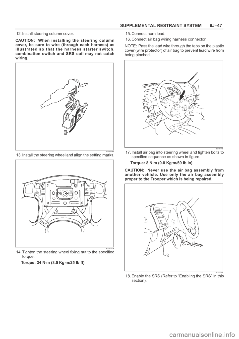
12. Install steering column cover.
CAUTION: When installing the steering column
cover, be sure to wire (through each harness) as
illustrated so that the harness starter switch,
combination switch and SRS coil may not catch
wiring.
825RS048
13. Install the steering wheel and align the setting marks.
430RS004
14. Tighten the steering wheel fixing nut to the specified
torque.
Torque: 34 Nꞏm (3.5 Kgꞏm/25 Ib ft)15. Connect horn lead.
16. Connect air bag wiring harness connector.
NOTE: Pass the lead wire through the tabs on the plastic
cover (wire protector) of air bag to prevent lead wire from
being pinched.
827RT009
17. Install air bag into steering wheel and tighten bolts to
specified sequence as shown in figure.
Torque: 8 Nꞏm (0.8 Kgꞏm/69 Ib in)
CAUTION: Never use the air bag assembly from
another vehicle. Use only the air bag assembly
proper to the Trooper which is being repaired.
827RT008
18. Enable the SRS (Refer to “Enabling the SRS” in this
section).
Page 3485 of 6000
SUPPLEMENTAL RESTRAINT SYSTEM 9J–48
Passenger Air Bag Assembly
Service Precautions
WARNING: SAFETY PRECAUTIONS MUST BE
FOLLOWED WHEN HANDLING A DEPLOYED AIR
BAG ASSEMBLY. AFTER DEPLOYMENT, THE AIR
BAG ASSEMBLY SURFACE MAY CONTAIN A SMALL
AMOUNT OF SODIUM HYDROXIDE, A BY–PRODUCT
OF THE DEPLOYMENT REACTION, THAT IS
IRRITATING TO THE SKIN AND EYES. MOST OF THE
POWER ON THE AIR BAG ASSEMBLY IS
HARMLESS. AS A PRECAUTION, WEAR GLOVES
AND SAFETY GLASSES WHEN HANDLING A
DEPLOYED AIR BAG ASSEMBLY, AND WASH YOUR
HANDS WITH MILD SOAP AND WATER
AFTERWARDS.
WARNING: WHEN CARRYING A LIVE AIR BAG
ASSEMBLY, MAKE SURE THE BAG AND TRIM
COVER ARE POINTED AWAY FROM YOU. NEVER
CARRY AIR BAG ASSEMBLY BY THE WIRES OR
CONNECTOR ON THE UNDERSIDE OF MODULE. IN
THE CASE OF AN ACCIDENTAL DEPLOYMENT, THE
BAG WILL THEN DEPLOY WITH MINIMAL CHANCE
OF INJURY. WHEN PLACING ALIVE AIR BAG
ASSEMBLY ON A BENCH OR OTHER SURFACE,
ALWAYS FACE BAG AND RIM COVER UP, AWAY
FROM THE SURFACE. NEVER REST A STEERING
COLUMN ASSEMBLY ON THE STEERING WHEEL
WITH THE AIR BAG ASSEMBLY FACE DOWN AND
COLUMN VERTICAL. THIS IS NECESSARY SO THAT
A FREE SPACE IS PROVIDED TO ALLOW THE AIR
BAG ASSEMBLY TO EXPAND IN THE UNLIKELY
EVENT OF ACCIDENTAL DEPLOYMENT.
OTHERWISE, PERSONAL INJURY COULD RESULT.
NOTE: IN THE EVENT DEPLOYMENT HAS
OCCURRED, INSPECT COIL ASSEMBLY WIRE FOR
ANY SIGNS OF SCORCHING, MELTING OR ANY
OTHER DAMAGE DUE TO EXCESSIVE HEAT. IF THE
COIL HAS BEEN DAMAGED, REPLACE IT.
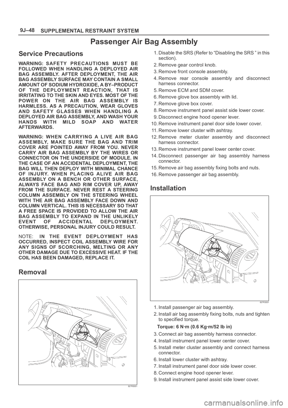
Removal
827RS001
1. Disable the SRS (Refer to “Disabling the SRS ” in this
section).
2. Remove gear control knob.
3. Remove front console assembly.
4. Remove rear console assembly and disconnect
harness connector.
5. Remove ECM and SDM cover.
6. Remove glove box assembly with lid.
7. Remove glove box cover.
8. Remove instrument panel assist side lower cover.
9. Disconnect engine hood opener lever.
10. Remove instrument panel door side lower cover.
11. Remove lower cluster with ashtray.
12. Remove meter cluster assembly and disconnect
harness connector.
13. Remove instrument panel lower center cover.
14. Disconnect passenger air bag assembly harness
connector.
15. Remove air bag assembly fixing bolts and nuts.
16. Remove passenger air bag assembly.
Installation
827RS001
1. Install passenger air bag assembly.
2. Install air bag assembly fixing bolts, nuts and tighten
to specified torque.
Torque: 6 Nꞏm (0.6 Kgꞏm/52 Ib in)
3. Connect air bag assembly harness connector.
4. Install instrument panel lower center cover.
5. Install meter cluster assembly and connect harness
connector.
6. Install lower cluster with ashtray.
7. Install instrument panel door side lower cover.
8. Connect engine hood opener lever.
9. Install instrument panel assist side lower cover.
Page 3487 of 6000
SUPPLEMENTAL RESTRAINT SYSTEM 9J–50
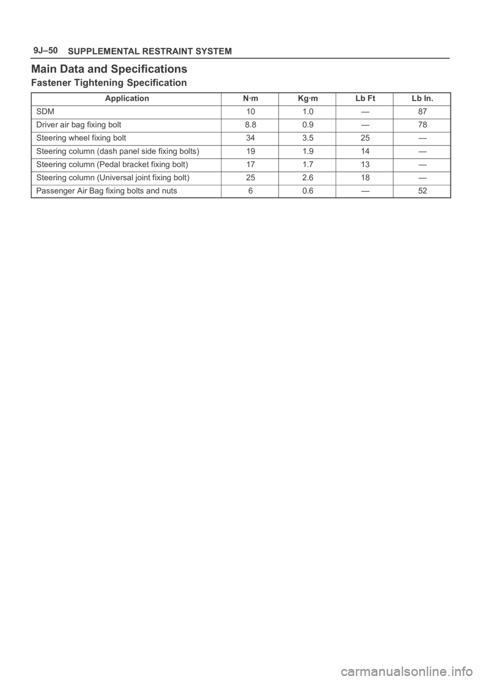
Main Data and Specifications
Fastener Tightening Specification
ApplicationNꞏmKgꞏmLb FtLb In.
SDM101.0—87
Driver air bag fixing bolt8.80.9—78
Steering wheel fixing bolt343.525—
Steering column (dash panel side fixing bolts)191.914—
Steering column (Pedal bracket fixing bolt)171.713—
Steering column (Universal joint fixing bolt)252.618—
Passenger Air Bag fixing bolts and nuts60.6—52
Page 3942 of 6000
DIFFERENTIAL (FRONT) 4A1–2
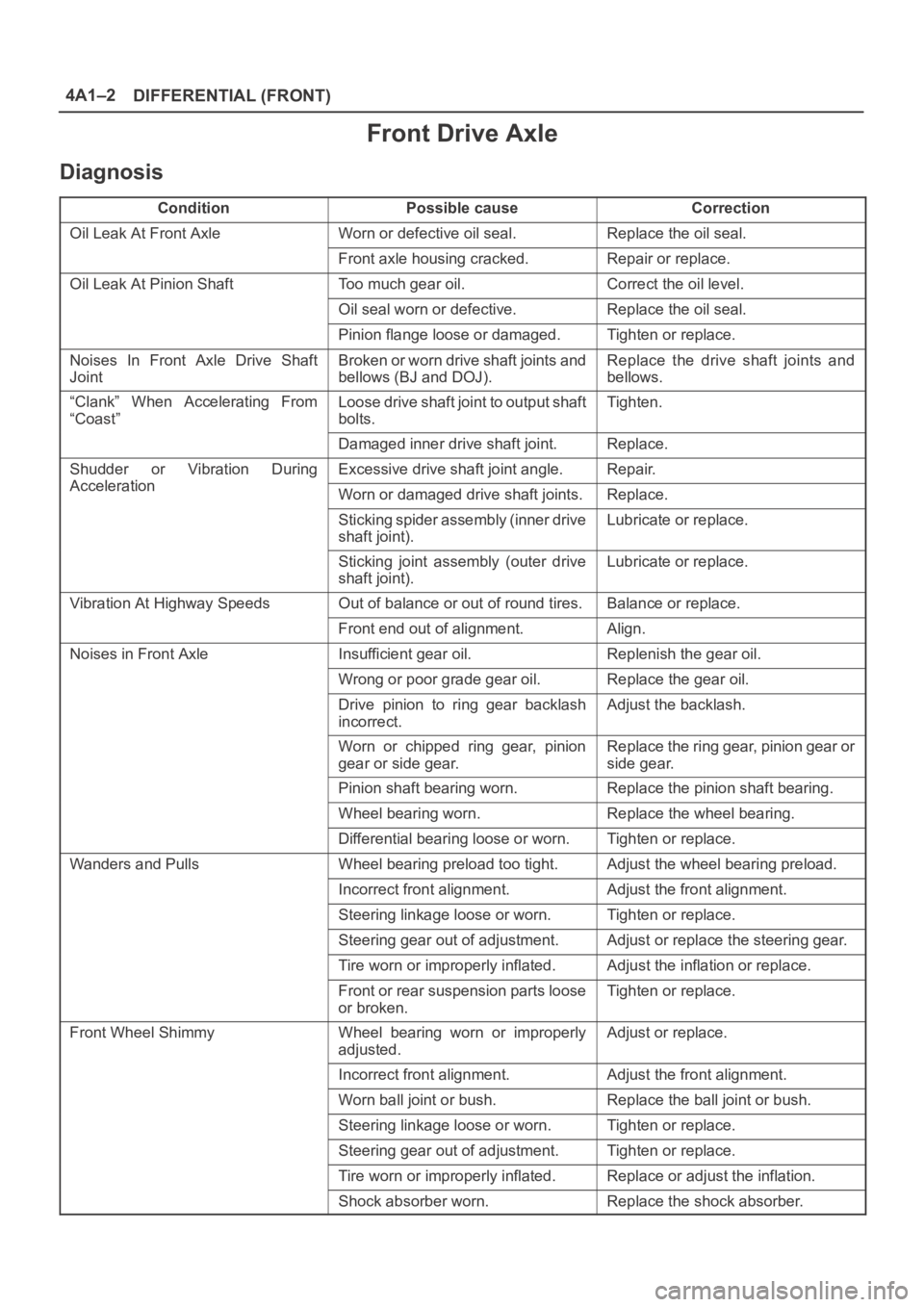
Front Drive Axle
Diagnosis
ConditionPossible causeCorrection
Oil Leak At Front AxleWorn or defective oil seal.Replace the oil seal.
Front axle housing cracked.Repair or replace.
Oil Leak At Pinion ShaftToo much gear oil.Correct the oil level.
Oil seal worn or defective.Replace the oil seal.
Pinion flange loose or damaged.Tighten or replace.
Noises In Front Axle Drive Shaft
JointBroken or worn drive shaft joints and
bellows (BJ and DOJ).Replace the drive shaft joints and
bellows.
“Clank” When Accelerating From
“Coast”Loose drive shaft joint to output shaft
bolts.Tighten.
Damaged inner drive shaft joint.Replace.
Shudder or Vibration During
Acceleration
Excessive drive shaft joint angle.Repair.
AccelerationWorn or damaged drive shaft joints.Replace.
Sticking spider assembly (inner drive
shaft joint).Lubricate or replace.
Sticking joint assembly (outer drive
shaft joint).Lubricate or replace.
Vibration At Highway SpeedsOut of balance or out of round tires.Balance or replace.
Front end out of alignment.Align.
Noises in Front AxleInsufficient gear oil.Replenish the gear oil.
Wrong or poor grade gear oil.Replace the gear oil.
Drive pinion to ring gear backlash
incorrect.Adjust the backlash.
Worn or chipped ring gear, pinion
gear or side gear.Replace the ring gear, pinion gear or
side gear.
Pinion shaft bearing worn.Replace the pinion shaft bearing.
Wheel bearing worn.Replace the wheel bearing.
Differential bearing loose or worn.Tighten or replace.
Wanders and PullsWheel bearing preload too tight.Adjust the wheel bearing preload.
Incorrect front alignment.Adjust the front alignment.
Steering linkage loose or worn.Tighten or replace.
Steering gear out of adjustment.Adjust or replace the steering gear.
Tire worn or improperly inflated.Adjust the inflation or replace.
Front or rear suspension parts loose
or broken.Tighten or replace.
Front Wheel ShimmyWheel bearing worn or improperly
adjusted.Adjust or replace.
Incorrect front alignment.Adjust the front alignment.
Worn ball joint or bush.Replace the ball joint or bush.
Steering linkage loose or worn.Tighten or replace.
Steering gear out of adjustment.Tighten or replace.
Tire worn or improperly inflated.Replace or adjust the inflation.
Shock absorber worn.Replace the shock absorber.
Page 3971 of 6000
4A2A–2
DIFFERENTIAL (REAR 220mm)
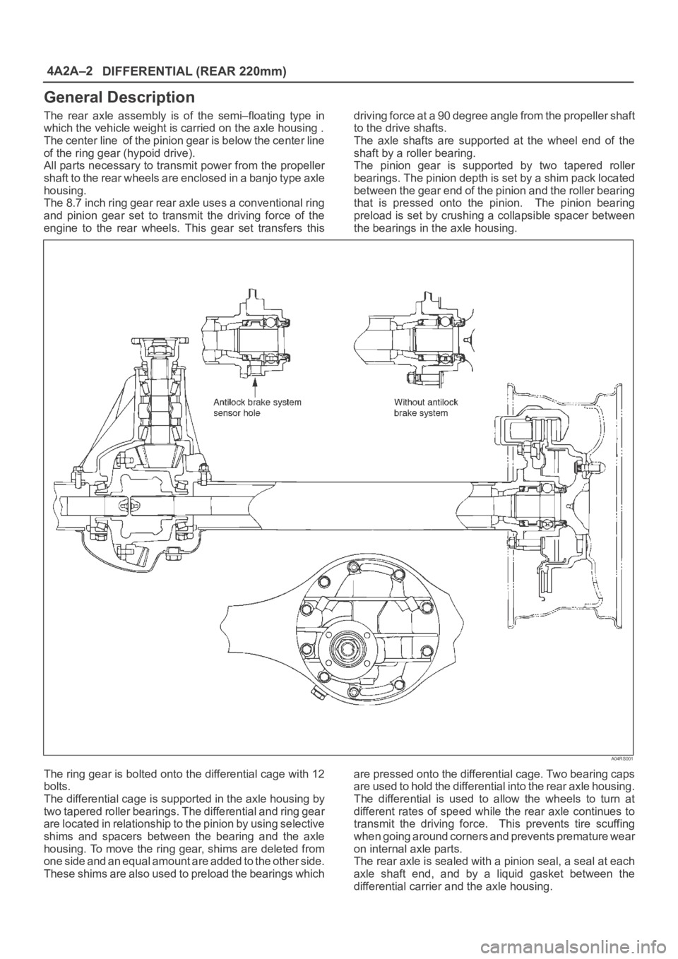
General Description
The rear axle assembly is of the semi–floating type in
which the vehicle weight is carried on the axle housing .
The center line of the pinion gear is below the center line
of the ring gear (hypoid drive).
All parts necessary to transmit power from the propeller
shaft to the rear wheels are enclosed in a banjo type axle
housing.
The 8.7 inch ring gear rear axle uses a conventional ring
and pinion gear set to transmit the driving force of the
engine to the rear wheels. This gear set transfers thisdriving force at a 90 degree angle from the propeller shaft
to the drive shafts.
The axle shafts are supported at the wheel end of the
shaft by a roller bearing.
The pinion gear is supported by two tapered roller
bearings. The pinion depth is set by a shim pack located
between the gear end of the pinion and the roller bearing
that is pressed onto the pinion. The pinion bearing
preload is set by crushing a collapsible spacer between
the bearings in the axle housing.
A04RS001
The ring gear is bolted onto the differential cage with 12
bolts.
The differential cage is supported in the axle housing by
two tapered roller bearings. The differential and ring gear
are located in relationship to the pinion by using selective
shims and spacers between the bearing and the axle
housing. To move the ring gear, shims are deleted from
one side and an equal amount are added to the other side.
These shims are also used to preload the bearings whichare pressed onto the differential cage. Two bearing caps
are used to hold the differential into the rear axle housing.
The differential is used to allow the wheels to turn at
different rates of speed while the rear axle continues to
transmit the driving force. This prevents tire scuffing
when going around corners and prevents premature wear
on internal axle parts.
The rear axle is sealed with a pinion seal, a seal at each
axle shaft end, and by a liquid gasket between the
differential carrier and the axle housing.
Page 3976 of 6000
DIFFERENTIAL (REAR 220mm)
4A2A–7
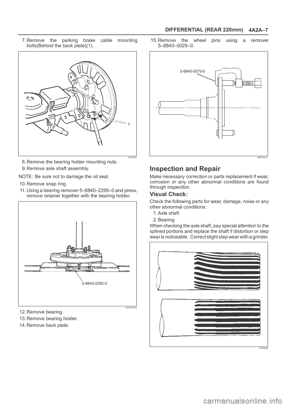
7.Remove the parking brake cable mounting
bolts(Behind the back plate)(1).
311RS001
8. Remove the bearing holder mounting nuts.
9. Remove axle shaft assembly.
NOTE: Be sure not to damage the oil seal.
10. Remove snap ring.
11. Using a bearing remover 5–8840–2295–0 and press,
remove retainer together with the bearing holder.
420RY00012
12. Remove bearing.
13. Remove bearing holder.
14. Remove back plate.15. Remove the wheel pins using a remover
5–8840–0029–0.
420RY00011
Inspection and Repair
Make necessary correction or parts replacement if wear,
corrosion or any other abnormal conditions are found
through inspection.
Visual Check:
Check the following parts for wear, damage, noise or any
other abnormal conditions:
1. Axle shaft
2. Bearing
When checking the axle shaft, pay special attention to the
splined portions and replace the shaft if distortion or step
wear is noticeable. Correct slight step wear with a grinder.
420RS008