Page 1814 of 6000

ENGINE MECHANICAL 6A – 81
8. Cylinder Block Rear Plate (A/T)
Align the rear plate with the cylinder block dowel
pins.
Tighten the rear plate to the specified torque.
Torque: 97 Nꞏm (9.9 kgꞏm/72 lb ft)
9. Flywheel housing (M/T)
Align the flywheel housing with the cylinder block
dowel pins.
Tighten the bolt to the specified torque.
Torque: 97 Nꞏm (9.9 kgꞏm/72 lb ft)
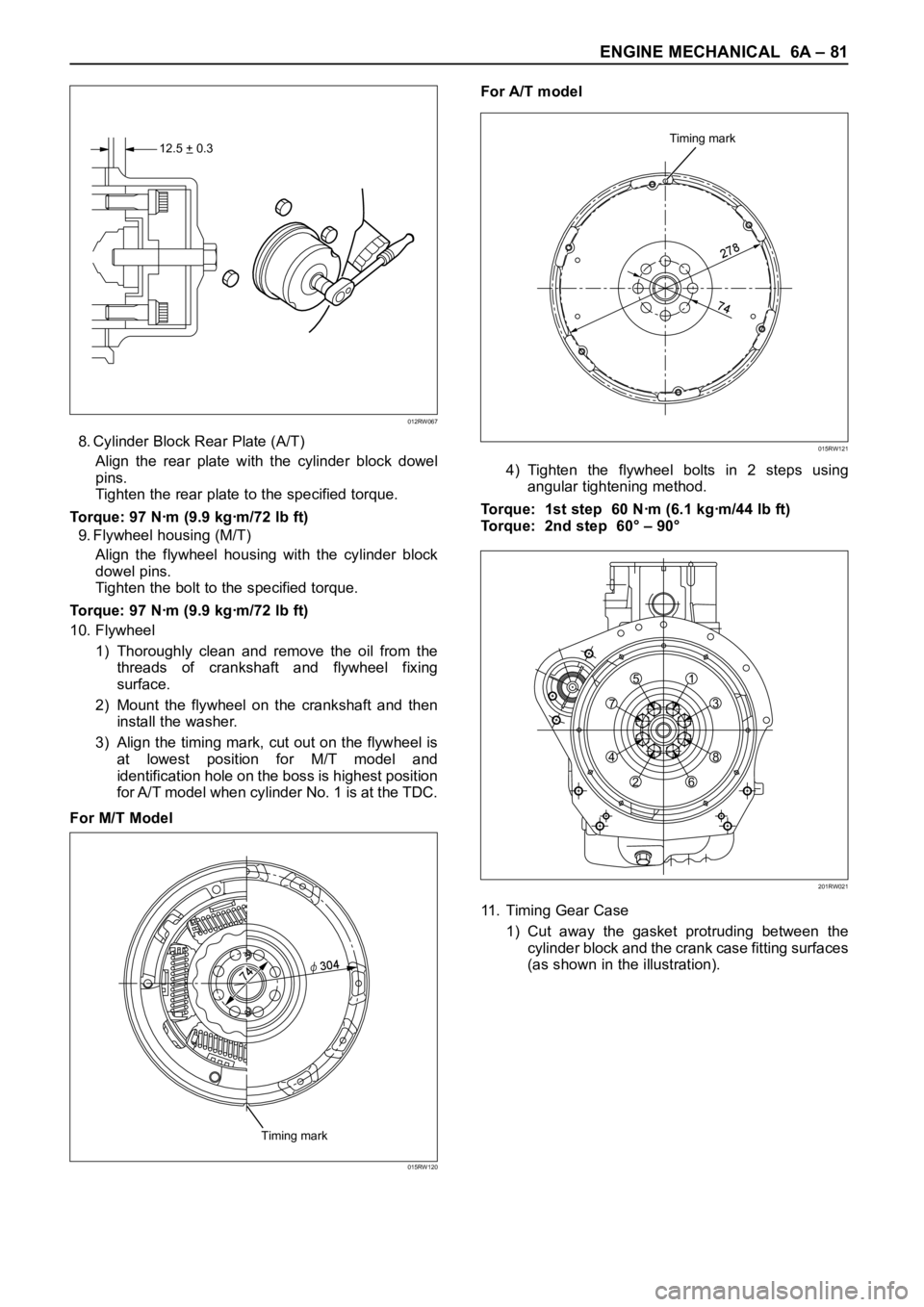
10. Flywheel
1) Thoroughly clean and remove the oil from the
threads of crankshaft and flywheel fixing
surface.
2) Mount the flywheel on the crankshaft and then
install the washer.
3) Align the timing mark, cut out on the flywheel is
at lowest position for M/T model and
identification hole on the boss is highest position
for A/T model when cylinder No. 1 is at the TDC.
For M/T ModelFor A/T model
4) Tighten the flywheel bolts in 2 steps using
angular tightening method.
Torque: 1st step 60 Nꞏm (6.1 kgꞏm/44 lb ft)
Torque: 2nd step 60° – 90°
11. Timing Gear Case
1) Cut away the gasket protruding between the
cylinder block and the crank case fitting surfaces
(as shown in the illustration).
12.5 + 0.3–
012RW067
Timing mark
2
78
74
015RW121
Timing mark
7
4φ
304
015RW120
751
3
8
6 2 4
201RW021
Page 1830 of 6000

ENGINE MECHANICAL 6A – 97
11. Use the special tool to install the crankshaft front oil
seal to timing gear case.
Front Oil Seal Installer: 5-8840-2061-0
1) Check fit-of the oil seal and gear case cover at
the front end.
Standard: 0.5 – 2.5 mm (0.0197 – 0.0984 in)
NOTE: Apply engine oil to oil seal lip before installation
of the seal.
12. Install the oil pan assembly to original position and
tighten to specified torque.
Torque: 22 Nꞏm (2.2 kgꞏm/15.9 lb ft)
13. Crankshaft Rear Oil Seal
1) Tighten the adapter to the crankshaft rear end
with 2 bolts.
2) Insert the oil seal into the adapter.
3) Insert the sleeve into the adapter and tighten it
with a bolt (M12 x 1.75L = 70) until the adapter
hits the sleeve.
4) Remove the adapter and the sleeve.
5) With the seal pressed in, check the dimension of
the oil seal outside end and crankshaft end.
Standard Dimension = 12.5 ± 0.3 mm
Oil Seal Installer: 5-8840-2359-014. Cylinder Block Rear Plate (A/T Model)
1) Tighten the cylinder block rear plate fixing bolts
to the specified torque.
Torque: 97 Nꞏm (9.9 kgꞏm/72 lb ft)
15. Flywheel Housing (M/T Model)
1) Install flywheel housing aligned with the dowel
pin on the cylinder block.
2) Tighten the flywheel housing fixing bolts to the
specified torque.
Torque: 97 Nꞏm (9.9 kgꞏm/72 lb ft)
16. Flywheel
1) Refer to “Crankshaft” in this manual.
17. Cylinder Head Assembly
1) Refer to “Cylinder Head” in this manual.
015RW074
12.5 + 0.3–
012RW067
Page 2186 of 6000

7A–32
AUTOMATIC TRANSMISSION (4L30–E)
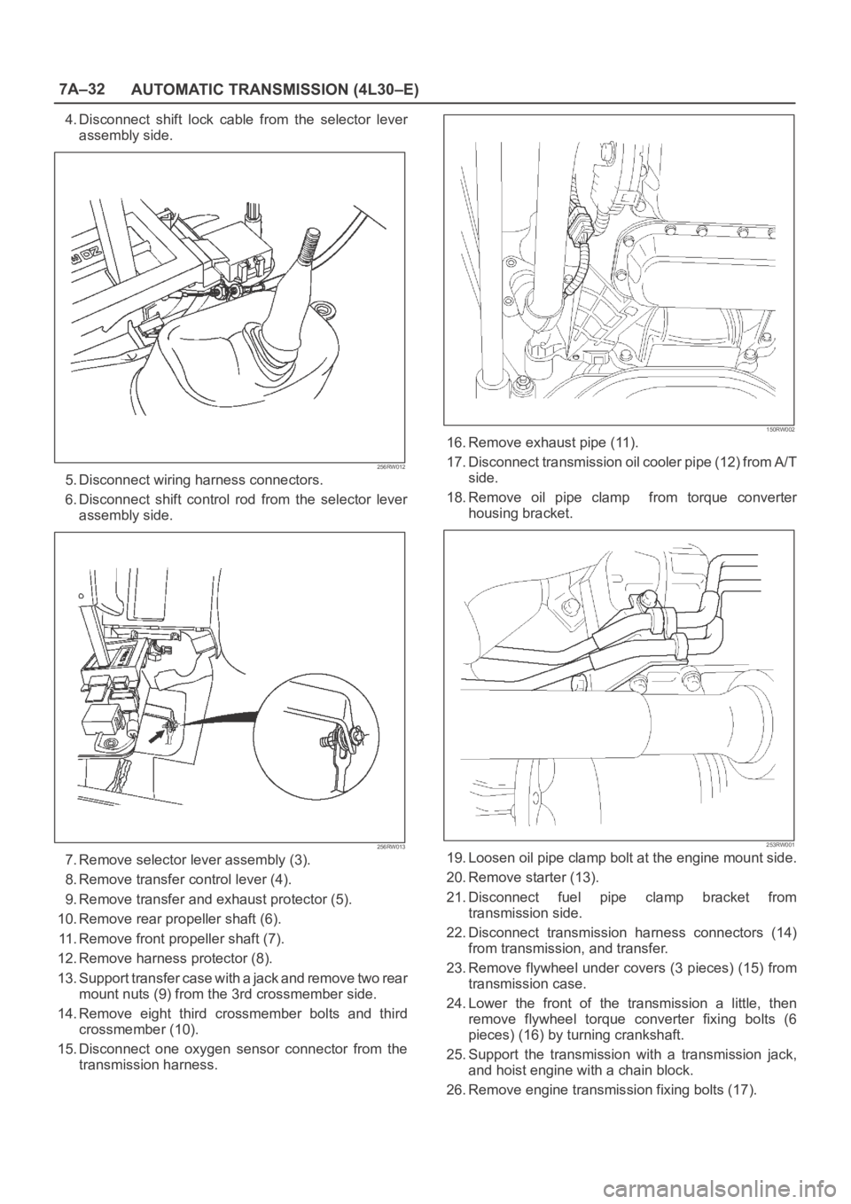
4. Disconnect shift lock cable from the selector lever
assembly side.
256RW012
5. Disconnect wiring harness connectors.
6. Disconnect shift control rod from the selector lever
assembly side.
256RW013
7. Remove selector lever assembly (3).
8. Remove transfer control lever (4).
9. Remove transfer and exhaust protector (5).
10. Remove rear propeller shaft (6).
11. Remove front propeller shaft (7).
12. Remove harness protector (8).
13. Support transfer case with a jack and remove two rear
mount nuts (9) from the 3rd crossmember side.
14. Remove eight third crossmember bolts and third
crossmember (10).
15. Disconnect one oxygen sensor connector from the
transmission harness.
150RW002
16. Remove exhaust pipe (11).
17. Disconnect transmission oil cooler pipe (12) from A/T
side.
18. Remove oil pipe clamp from torque converter
housing bracket.
253RW001
19. Loosen oil pipe clamp bolt at the engine mount side.
20. Remove starter (13).
21. Disconnect fuel pipe clamp bracket from
transmission side.
22. Disconnect transmission harness connectors (14)
from transmission, and transfer.
23. Remove flywheel under covers (3 pieces) (15) from
transmission case.
24. Lower the front of the transmission a little, then
remove flywheel torque converter fixing bolts (6
pieces) (16) by turning crankshaft.
25. Support the transmission with a transmission jack,
and hoist engine with a chain block.
26. Remove engine transmission fixing bolts (17).
Page 2187 of 6000
7A–33 AUTOMATIC TRANSMISSION (4L30–E)
27. Remove transmission assembly (18).
Installation
1. Slowly raise transmission jack until front of the
transmission is aligned with rear of the engine, then
install transmission assembly.2. Tighten engine transmission bolts to the specified
torque.
F07RW041
3. Support transfer case with a jack, and remove the
transmission jack.
4. Install flywheel torque converter bolts (6 pieces) by
turning crankshaft.
Torque: 54 N
m (5.5 kgꞏm/40 lb ft)
NOTE: Do not reuse the flywheel torque converter bolt.
240RW005
Page 2188 of 6000

7A–34
AUTOMATIC TRANSMISSION (4L30–E)
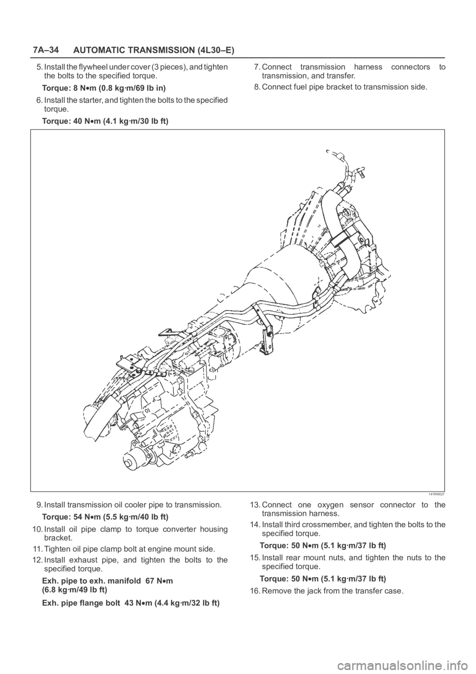
5. Install the flywheel under cover (3 pieces), and tighten
the bolts to the specified torque.
Torque: 8 N
m (0.8 kgꞏm/69 lb in)
6. Install the starter, and tighten the bolts to the specified
torque.
Torque: 40 N
m (4.1 kgꞏm/30 lb ft)7. Connect transmission harness connectors to
transmission, and transfer.
8. Connect fuel pipe bracket to transmission side.
141RW027
9. Install transmission oil cooler pipe to transmission.
Torque: 54 N
m (5.5 kgꞏm/40 lb ft)
10. Install oil pipe clamp to torque converter housing
bracket.
11. Tighten oil pipe clamp bolt at engine mount side.
12. Install exhaust pipe, and tighten the bolts to the
specified torque.
Exh. pipe to exh. manifold 67 N
m
(6.8 kgꞏm/49 lb ft)
Exh. pipe flange bolt 43 N
m (4.4 kgꞏm/32 lb ft)13. Connect one oxygen sensor connector to the
transmission harness.
14. Install third crossmember, and tighten the bolts to the
specified torque.
To r q u e : 5 0 N
m (5.1 kgꞏm/37 lb ft)
15. Install rear mount nuts, and tighten the nuts to the
specified torque.
To r q u e : 5 0 N
m (5.1 kgꞏm/37 lb ft)
16. Remove the jack from the transfer case.
Page 2327 of 6000
MANUAL TRANSMISSION7B–9
16. Remove the slave cylinder heat protector.
17. Remove the harness heat protector (6VE1).
(6VE1)
225RW006
18. Remove two transmission harness clamps and
bracket (6VE1).
19. Remove the slave cylinder.
206RW002
20. Remove the two dust cover from transmission case.
21. Support the transfer case with a jack.22. Remove two engine rear mount nuts.
(6VE1)
022RT002
23. Remove third crossmember (6VE1).
24. Remove third crossmember with rear mount rubber
(4JX1).
(4JX1)
022RW013
25. Remove two engine rear mount bolts (6VE1).
26. Remove the rear mount from the transmission
(6VE1).
27. Remove three flywheel under cover (6VE1).
Page 2519 of 6000
7C–10CLUTCH
5. Mark the flywheel, clutch cover and pressure plate lug
for alignment when installing.
6. Remove the release bearing (3) from the
transmission case .
7. Remove the shift fork snap pin.
8. Remove the shift fork pin and shift fork (4) from the
front cover.
9. Remove the front cover bolts.
10. Remove the front cover (5) from the transmission
case.
220RW088
11. Remove flywheel assembly and crankshaft bearing.
Do not remove except for replacement.
12. Use the remover 5–8840–2000–0 (J–5822) and
sliding hammer 5–8840–0019–0 (J–23907) to
remove the crankshaft bearing
015RW053
Inspection and Repair
Make necessary correction or parts replacement if wear,
damage, or any other abnormal condition are found
through inspection.
Pressure Plate Assembly
201RS002
1. Visually check the pressure plate friction surface for
excessive wear and heat cracks.
2. If excessive wear or deep heat cracks are present,
the pressure plate must be replaced.
Pressure Plate Warpage
201RS003
Page 2520 of 6000

CLUTCH7C–11
1. Use a straight edge and a feeler gauge to measure
the pressure plate friction surface flatness in four
directions.
2. If any of the measured values exceeds the specified
limit, the pressure plate must be replaced.
Pressure Plate Warpage
Limit: 0.3 mm (0.012 in)
Clutch Cover
201RS004
1. Visually check the entire clutch cover for excessive
wear, cracking, and other damage.
2. The clutch cover must be replaced if any of these
conditions are present.
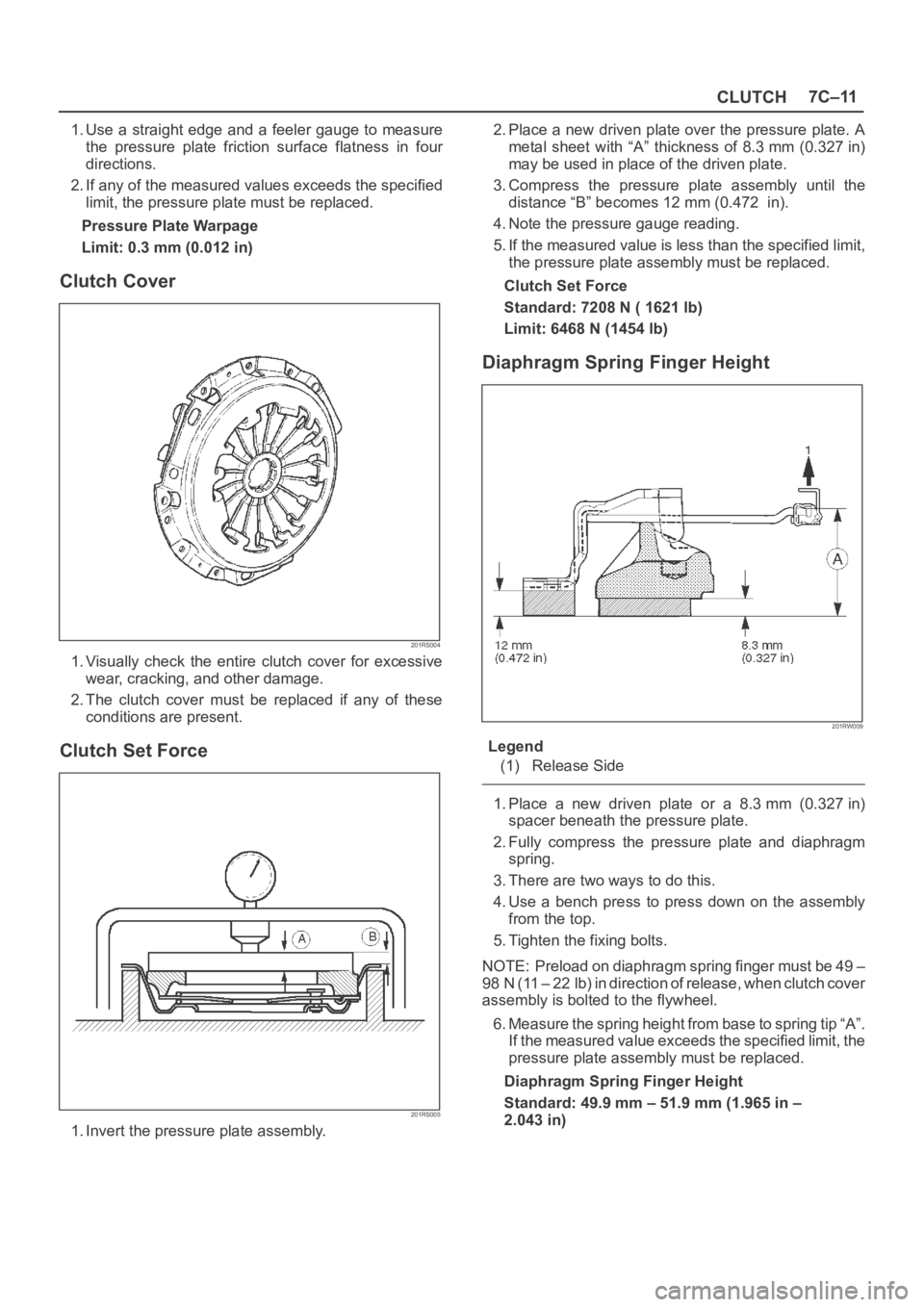
Clutch Set Force
201RS005
1. Invert the pressure plate assembly.2. Place a new driven plate over the pressure plate. A
metal sheet with “A” thickness of 8.3 mm (0.327 in)
may be used in place of the driven plate.
3. Compress the pressure plate assembly until the
distance “B” becomes 12 mm (0.472 in).
4. Note the pressure gauge reading.
5. If the measured value is less than the specified limit,
the pressure plate assembly must be replaced.
Clutch Set Force
Standard: 7208 N ( 1621 lb)
Limit: 6468 N (1454 lb)
Diaphragm Spring Finger Height
201RW009
Legend
(1) Release Side
1. Place a new driven plate or a 8.3 mm (0.327 in)
spacer beneath the pressure plate.
2. Fully compress the pressure plate and diaphragm
spring.
3. There are two ways to do this.
4. Use a bench press to press down on the assembly
from the top.
5. Tighten the fixing bolts.
NOTE: Preload on diaphragm spring finger must be 49 –
98 N (11 – 22 lb) in direction of release, when clutch cover
assembly is bolted to the flywheel.
6. Measure the spring height from base to spring tip “A”.
If the measured value exceeds the specified limit, the
pressure plate assembly must be replaced.
Diaphragm Spring Finger Height
Standard: 49.9 mm – 51.9 mm (1.965 in –
2.043 in)