1998 OPEL FRONTERA fuse
[x] Cancel search: fusePage 1921 of 6000
6E–28
4JX1–TC ENGINE DRIVEABILITY AND EMISSIONS
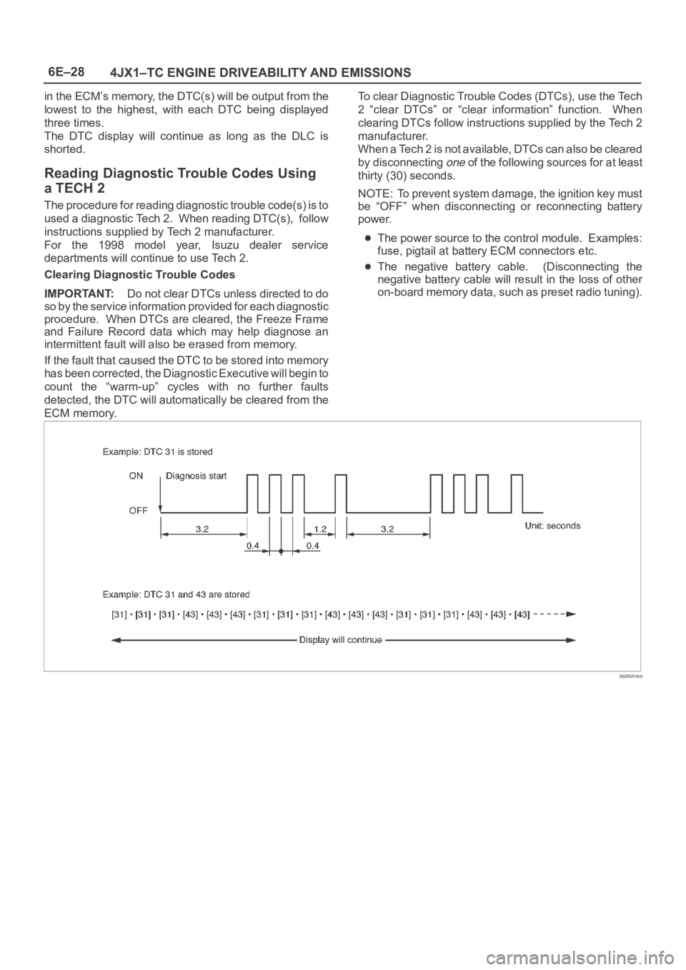
in the ECM’s memory, the DTC(s) will be output from the
lowest to the highest, with each DTC being displayed
three times.
The DTC display will continue as long as the DLC is
shorted.
Reading Diagnostic Trouble Codes Using
a TECH 2
The procedure for reading diagnostic trouble code(s) is to
used a diagnostic Tech 2. When reading DTC(s), follow
instructions supplied by Tech 2 manufacturer.
For the 1998 model year, Isuzu dealer service
departments will continue to use Tech 2.
Clearing Diagnostic Trouble Codes
IMPORTANT:Do not clear DTCs unless directed to do
so by the service information provided for each diagnostic
procedure. When DTCs are cleared, the Freeze Frame
and Failure Record data which may help diagnose an
intermittent fault will also be erased from memory.
If the fault that caused the DTC to be stored into memory
has been corrected, the Diagnostic Executive will begin to
count the “warm-up” cycles with no further faults
detected, the DTC will automatically be cleared from the
ECM memory.To clear Diagnostic Trouble Codes (DTCs), use the Tech
2 “clear DTCs” or “clear information” function. When
clearing DTCs follow instructions supplied by the Tech 2
manufacturer.
When a Tech 2 is not available, DTCs can also be cleared
by disconnecting
one of the following sources for at least
thirty (30) seconds.
NOTE: To prevent system damage, the ignition key must
be “OFF” when disconnecting or reconnecting battery
power.
The power source to the control module. Examples:
fuse, pigtail at battery ECM connectors etc.
The negative battery cable. (Disconnecting the
negative battery cable will result in the loss of other
on-board memory data, such as preset radio tuning).
060RW169
Page 1937 of 6000
6E–44
4JX1–TC ENGINE DRIVEABILITY AND EMISSIONS
No Malfunction Indicator Lamp (MIL)
060RW136
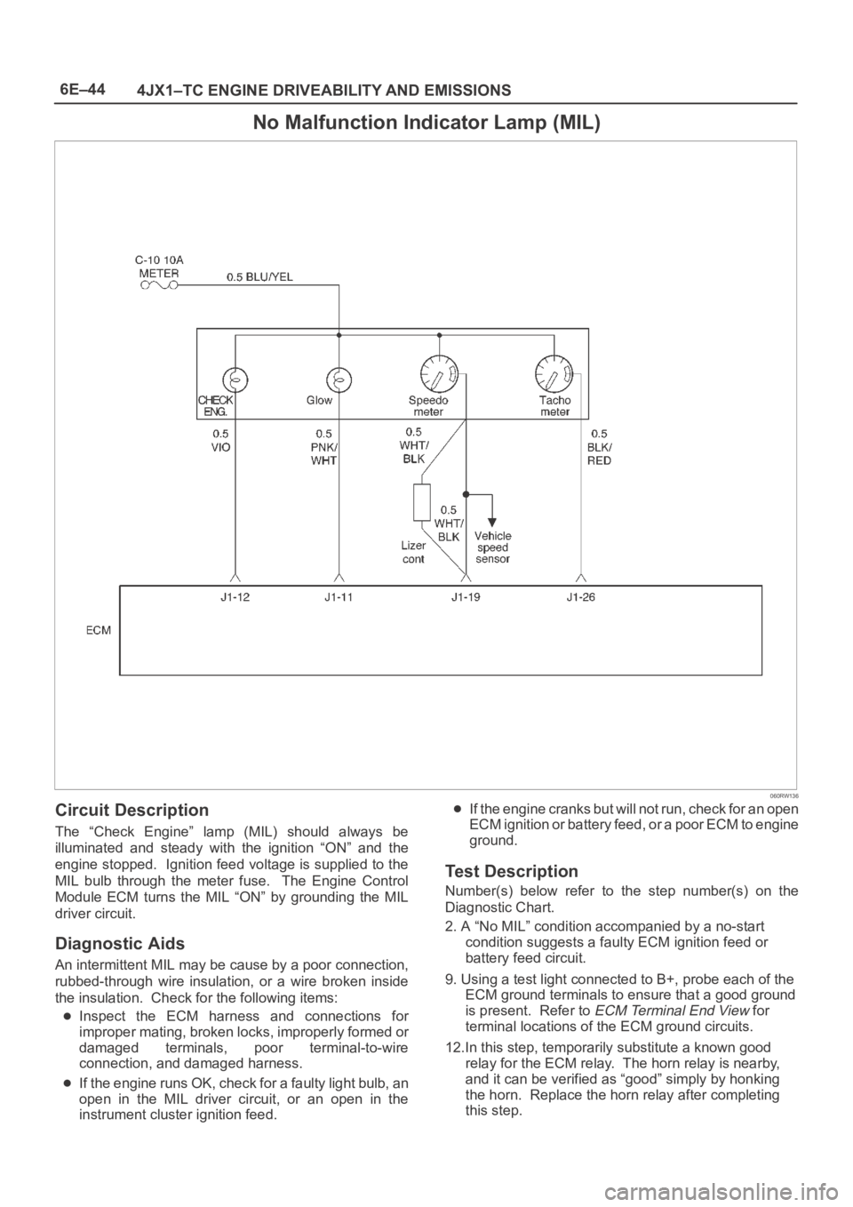
Circuit Description
The “Check Engine” lamp (MIL) should always be
illuminated and steady with the ignition “ON” and the
engine stopped. Ignition feed voltage is supplied to the
MIL bulb through the meter fuse. The Engine Control
Module ECM turns the MIL “ON” by grounding the MIL
driver circuit.
Diagnostic Aids
An intermittent MIL may be cause by a poor connection,
rubbed-through wire insulation, or a wire broken inside
the insulation. Check for the following items:
Inspect the ECM harness and connections for
improper mating, broken locks, improperly formed or
damaged terminals, poor terminal-to-wire
connection, and damaged harness.
If the engine runs OK, check for a faulty light bulb, an
open in the MIL driver circuit, or an open in the
instrument cluster ignition feed.
If the engine cranks but will not run, check for an open
ECM ignition or battery feed, or a poor ECM to engine
ground.
Test Description
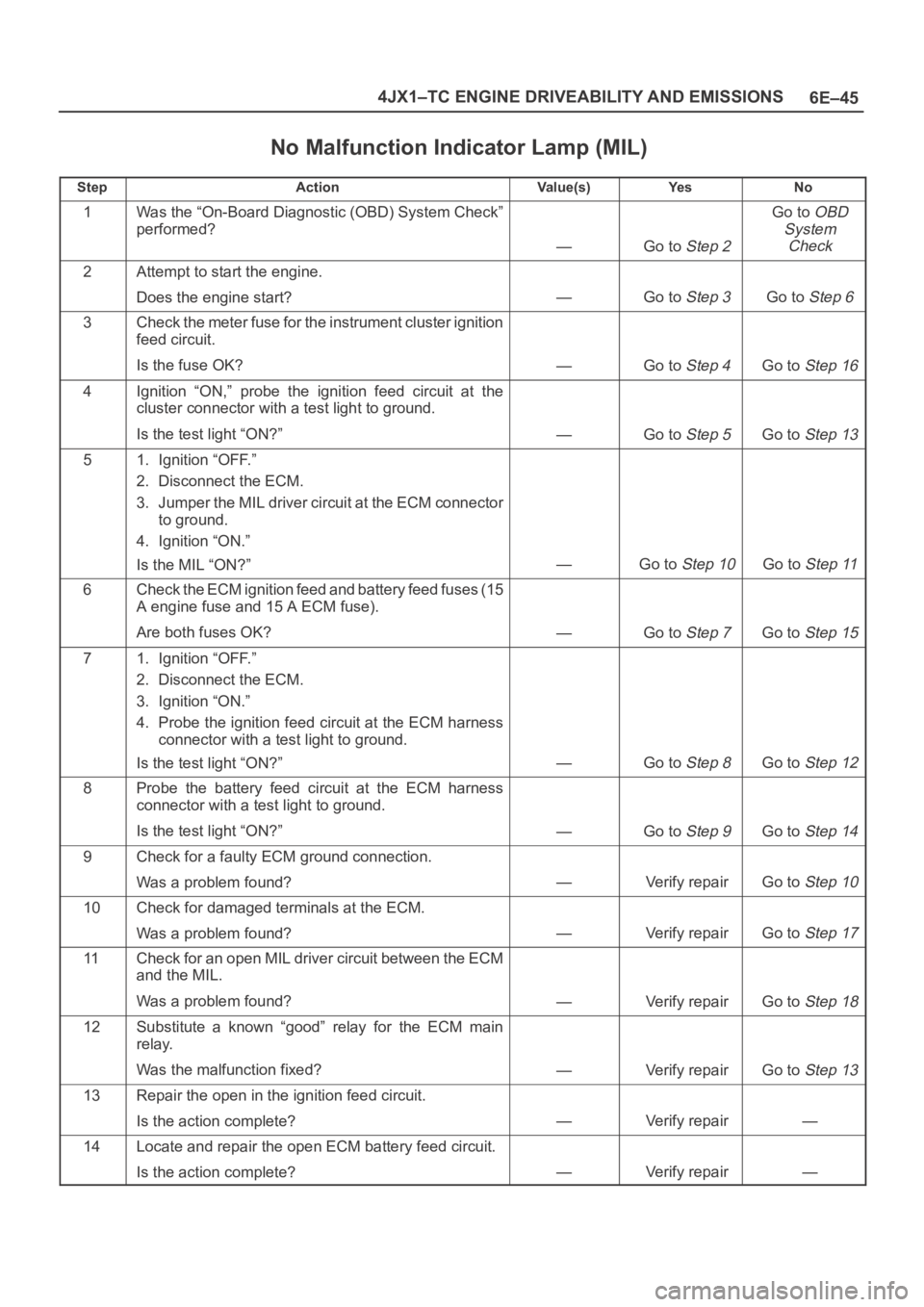
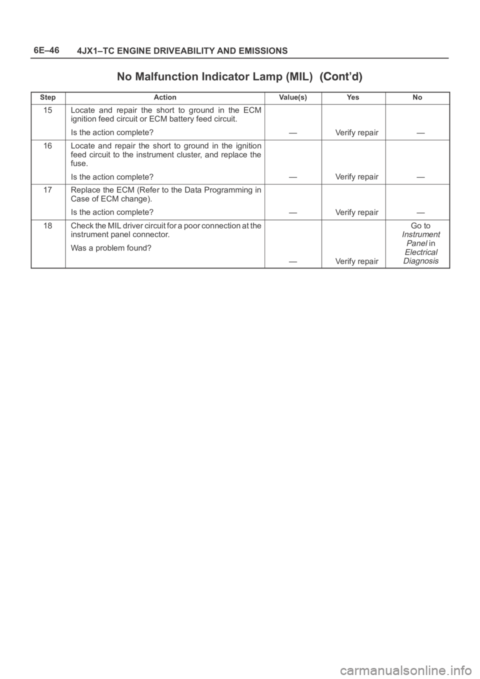
Number(s) below refer to the step number(s) on the
Diagnostic Chart.
2. A “No MIL” condition accompanied by a no-start
condition suggests a faulty ECM ignition feed or
battery feed circuit.
9. Using a test light connected to B+, probe each of the
ECM ground terminals to ensure that a good ground
is present. Refer to
ECM Terminal End View for
terminal locations of the ECM ground circuits.
12.In this step, temporarily substitute a known good
relay for the ECM relay. The horn relay is nearby,
and it can be verified as “good” simply by honking
the horn. Replace the horn relay after completing
this step.
Page 1938 of 6000
6E–45 4JX1–TC ENGINE DRIVEABILITY AND EMISSIONS
No Malfunction Indicator Lamp (MIL)
StepActionVa l u e ( s )Ye sNo
1Was the “On-Board Diagnostic (OBD) System Check”
performed?
—Go to Step 2
Go to OBD
System
Check
2Attempt to start the engine.
Does the engine start?
—Go to Step 3Go to Step 6
3Check the meter fuse for the instrument cluster ignition
feed circuit.
Is the fuse OK?
—Go to Step 4Go to Step 16
4Ignition “ON,” probe the ignition feed circuit at the
cluster connector with a test light to ground.
Is the test light “ON?”
—Go to Step 5Go to Step 13
51. Ignition “OFF.”
2. Disconnect the ECM.
3. Jumper the MIL driver circuit at the ECM connector
to ground.
4. Ignition “ON.”
Is the MIL “ON?”
—Go to Step 10Go to Step 11
6Check the ECM ignition feed and battery feed fuses (15
A engine fuse and 15 A ECM fuse).
Are both fuses OK?
—Go to Step 7Go to Step 15
71. Ignition “OFF.”
2. Disconnect the ECM.
3. Ignition “ON.”
4. Probe the ignition feed circuit at the ECM harness
connector with a test light to ground.
Is the test light “ON?”
—Go to Step 8Go to Step 12
8Probe the battery feed circuit at the ECM harness
connector with a test light to ground.
Is the test light “ON?”
—Go to Step 9Go to Step 14
9Check for a faulty ECM ground connection.
Was a problem found?
—Verify repairGo to Step 10
10Check for damaged terminals at the ECM.
Was a problem found?
—Verify repairGo to Step 17
11Check for an open MIL driver circuit between the ECM
and the MIL.
Was a problem found?
—Verify repairGo to Step 18
12Substitute a known “good” relay for the ECM main
relay.
Was the malfunction fixed?
—Verify repairGo to Step 13
13Repair the open in the ignition feed circuit.
Is the action complete?
—Verify repair—
14Locate and repair the open ECM battery feed circuit.
Is the action complete?
—Verify repair—
Page 1939 of 6000
6E–46
4JX1–TC ENGINE DRIVEABILITY AND EMISSIONS
No Malfunction Indicator Lamp (MIL)
StepNo Ye s Va l u e ( s ) Action
15Locate and repair the short to ground in the ECM
ignition feed circuit or ECM battery feed circuit.
Is the action complete?
—Verify repair—
16Locate and repair the short to ground in the ignition
feed circuit to the instrument cluster, and replace the
fuse.
Is the action complete?
—Verify repair—
17Replace the ECM (Refer to the Data Programming in
Case of ECM change).
Is the action complete?
—Verify repair—
18Check the MIL driver circuit for a poor connection at the
instrument panel connector.
Was a problem found?
—Verify repair
Go to
Instrument
Panel
in
Electrical
Diagnosis
Page 1942 of 6000
6E–49 4JX1–TC ENGINE DRIVEABILITY AND EMISSIONS
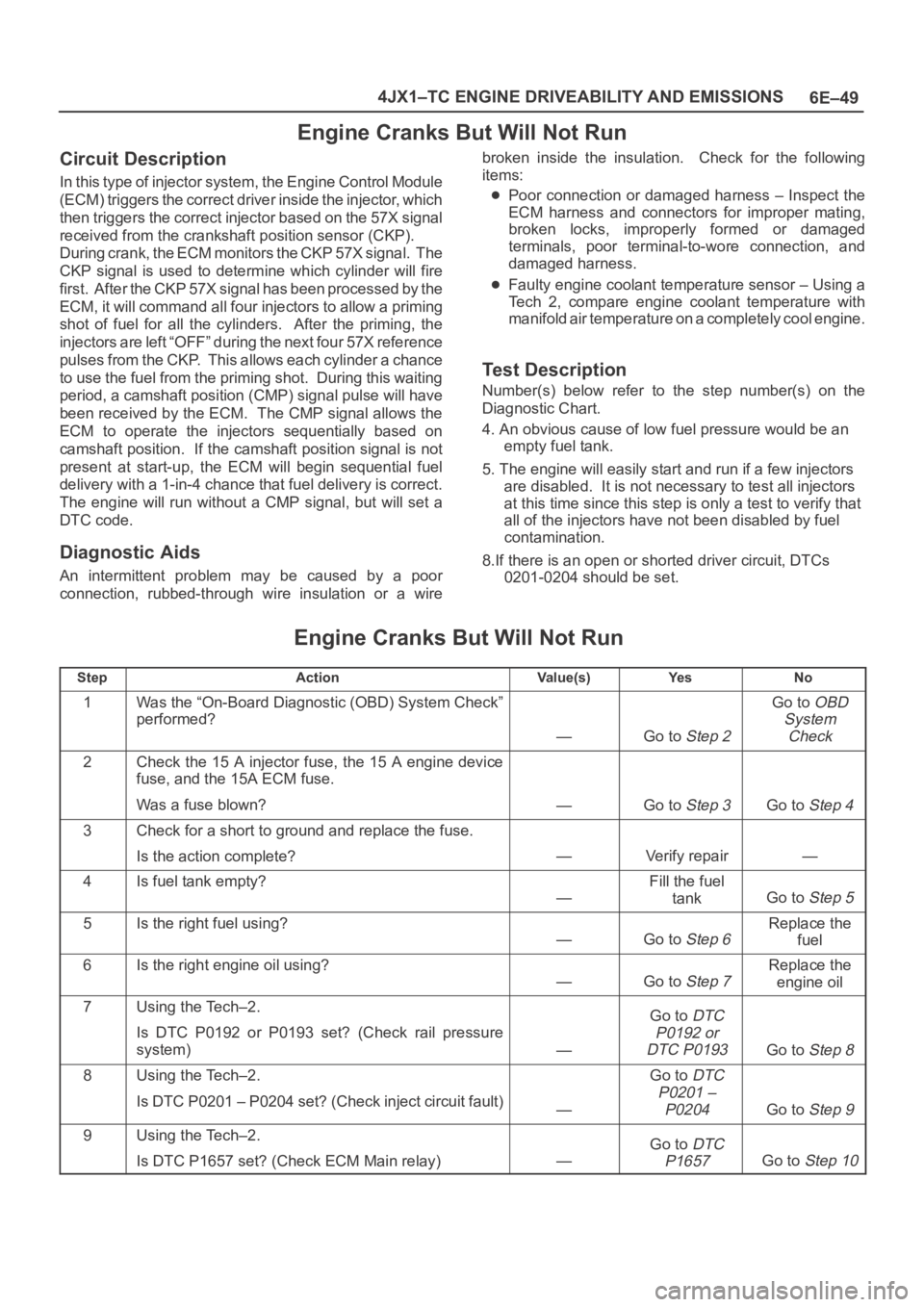
Engine Cranks But Will Not Run
Circuit Description
In this type of injector system, the Engine Control Module
(ECM) triggers the correct driver inside the injector, which
then triggers the correct injector based on the 57X signal
received from the crankshaft position sensor (CKP).
During crank, the ECM monitors the CKP 57X signal. The
CKP signal is used to determine which cylinder will fire
first. After the CKP 57X signal has been processed by the
ECM, it will command all four injectors to allow a priming
shot of fuel for all the cylinders. After the priming, the
injectors are left “OFF” during the next four 57X reference
pulses from the CKP. This allows each cylinder a chance
to use the fuel from the priming shot. During this waiting
period, a camshaft position (CMP) signal pulse will have
been received by the ECM. The CMP signal allows the
ECM to operate the injectors sequentially based on
camshaft position. If the camshaft position signal is not
present at start-up, the ECM will begin sequential fuel
delivery with a 1-in-4 chance that fuel delivery is correct.
The engine will run without a CMP signal, but will set a
DTC code.
Diagnostic Aids
An intermittent problem may be caused by a poor
connection, rubbed-through wire insulation or a wirebroken inside the insulation. Check for the following
items:
Poor connection or damaged harness – Inspect the
ECM harness and connectors for improper mating,
broken locks, improperly formed or damaged
terminals, poor terminal-to-wore connection, and
damaged harness.
Faulty engine coolant temperature sensor – Using a
Tech 2, compare engine coolant temperature with
manifold air temperature on a completely cool engine.
Test Description
Number(s) below refer to the step number(s) on the
Diagnostic Chart.
4. An obvious cause of low fuel pressure would be an
empty fuel tank.
5. The engine will easily start and run if a few injectors
are disabled. It is not necessary to test all injectors
at this time since this step is only a test to verify that
all of the injectors have not been disabled by fuel
contamination.
8.If there is an open or shorted driver circuit, DTCs
0201-0204 should be set.
Engine Cranks But Will Not Run
StepActionVa l u e ( s )Ye sNo
1Was the “On-Board Diagnostic (OBD) System Check”
performed?
—Go to Step 2
Go to OBD
System
Check
2Check the 15 A injector fuse, the 15 A engine device
fuse, and the 15A ECM fuse.
Was a fuse blown?
—Go to Step 3Go to Step 4
3Check for a short to ground and replace the fuse.
Is the action complete?
—Verify repair—
4Is fuel tank empty?
—
Fill the fuel
tank
Go to Step 5
5Is the right fuel using?
—Go to Step 6
Replace the
fuel
6Is the right engine oil using?
—Go to Step 7
Replace the
engine oil
7Using the Tech–2.
Is DTC P0192 or P0193 set? (Check rail pressure
system)
—
Go to DTC
P0192 or
DTC P0193
Go to Step 8
8Using the Tech–2.
Is DTC P0201 – P0204 set? (Check inject circuit fault)
—
Go to DTC
P0201 –
P0204
Go to Step 9
9Using the Tech–2.
Is DTC P1657 set? (Check ECM Main relay)
—
Go to DTC
P1657
Go to Step 10
Page 1979 of 6000
6E–86
4JX1–TC ENGINE DRIVEABILITY AND EMISSIONS
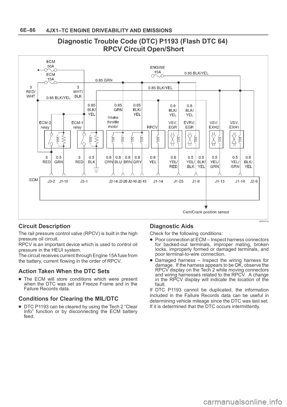
Diagnostic Trouble Code (DTC) P1193 (Flash DTC 64)
RPCV Circuit Open/Short
060RW135
Circuit Description
The rail pressure control valve (RPCV) is built in the high
pressure oil circuit.
RPCV is an important device which is used to control oil
pressure in the HEUI system.
The circuit receives current through Engine 15A fuse from
the battery, current flowing in the order of RPCV.
Action Taken When the DTC Sets
The ECM will store conditions which were present
when the DTC was set as Freeze Frame and in the
Failure Records data.
Conditions for Clearing the MIL/DTC
DTC P1193 can be cleared by using the Tech 2 “Clear
Info” function or by disconnecting the ECM battery
feed.
Diagnostic Aids
Check for the following conditions:
Poor connection at ECM – Inspect harness connectors
for backed-out terminals, improper mating, broken
locks, improperly formed or damaged terminals, and
poor terminal-to-wire connection.
Damaged harness – Inspect the wiring harness for
damage. If the harness appears to be OK, observe the
RPCV display on the Tech 2 while moving connectors
and wiring harnesses related to the RPCV. A change
in the RPCV display will indicate the location of the
fault.
If DTC P1193 cannot be duplicated, the information
included in the Failure Records data can be useful in
determining vehicle mileage since the DTC was last set.
If it is determined that the DTC occurs intermittently.
Page 1980 of 6000
6E–87 4JX1–TC ENGINE DRIVEABILITY AND EMISSIONS
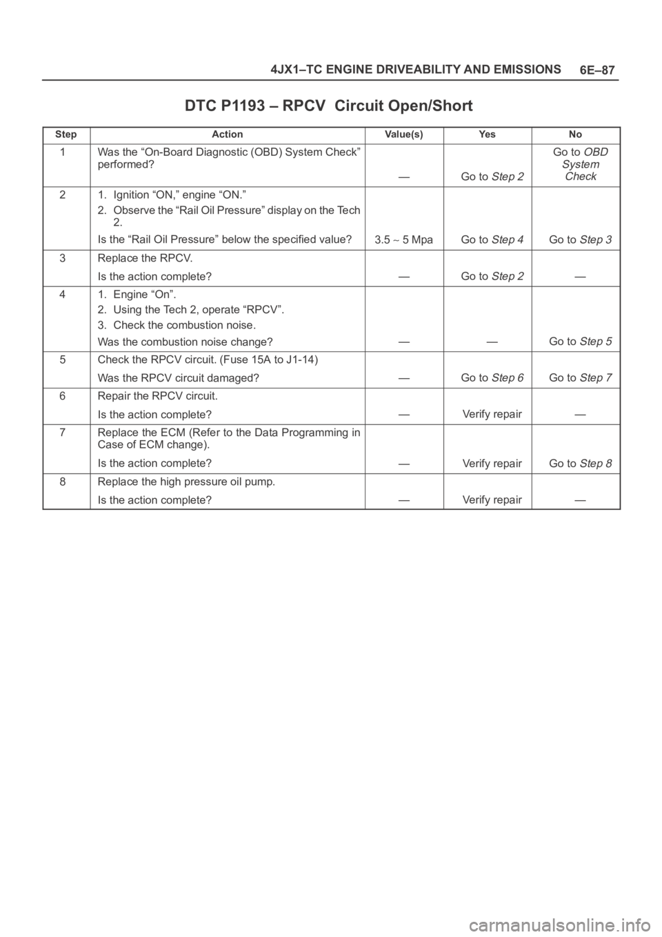
DTC P1193 – RPCV Circuit Open/Short
StepActionVa l u e ( s )Ye sNo
1Was the “On-Board Diagnostic (OBD) System Check”
performed?
—Go to Step 2
Go to OBD
System
Check
21. Ignition “ON,” engine “ON.”
2. Observe the “Rail Oil Pressure” display on the Tech
2.
Is the “Rail Oil Pressure” below the specified value?
3.5 5 MpaGo to Step 4Go to Step 3
3Replace the RPCV.
Is the action complete?
—Go to Step 2—
41. Engine “On”.
2. Using the Tech 2, operate “RPCV”.
3. Check the combustion noise.
Was the combustion noise change?
——Go to Step 5
5Check the RPCV circuit. (Fuse 15A to J1-14)
Was the RPCV circuit damaged?
—Go to Step 6Go to Step 7
6Repair the RPCV circuit.
Is the action complete?
—Verify repair—
7Replace the ECM (Refer to the Data Programming in
Case of ECM change).
Is the action complete?
—Verify repairGo to Step 8
8Replace the high pressure oil pump.
Is the action complete?
—Verify repair—
Page 1986 of 6000
6E–93 4JX1–TC ENGINE DRIVEABILITY AND EMISSIONS
Circuit Description
The rail pressure control valve (RPCV) is built in the high
pressure oil circuit.
RPCV is an important device which is used to control oil
pressure in the HEUI system.
The circuit receives current through Engine 15A fuse from
the battery, current flowing in the order of RPCV.
Action Taken When the DTC Sets
The ECM will store conditions which were present
when the DTC was set as Freeze Frame and in the
Failure Records data.
Conditions for Clearing the MIL/DTC
DTC P1196 can be cleared by using the Tech 2 “Clear
Info” function or by disconnecting the ECM battery
feed.
Diagnostic Aids
Check for the following conditions:
Poor connection at ECM – Inspect harness connectors
for backed-out terminals, improper mating, broken
locks, improperly formed or damaged terminals, and
poor terminal-to-wire connection.
Damaged harness – Inspect the wiring harness for
damage. If the harness appears to be OK, observe the
Rail Pressure Control display on the Tech 2 while
moving connectors and wiring harnesses related to the
Rail Pressure Control. A change in the Rail Pressure
Control display will indicate the location of the fault.
If DTC P1196 cannot be duplicated, the information
included in the Failure Records data can be useful in
determining vehicle mileage since the DTC was last set.
If it is determined that the DTC occurs intermittently.
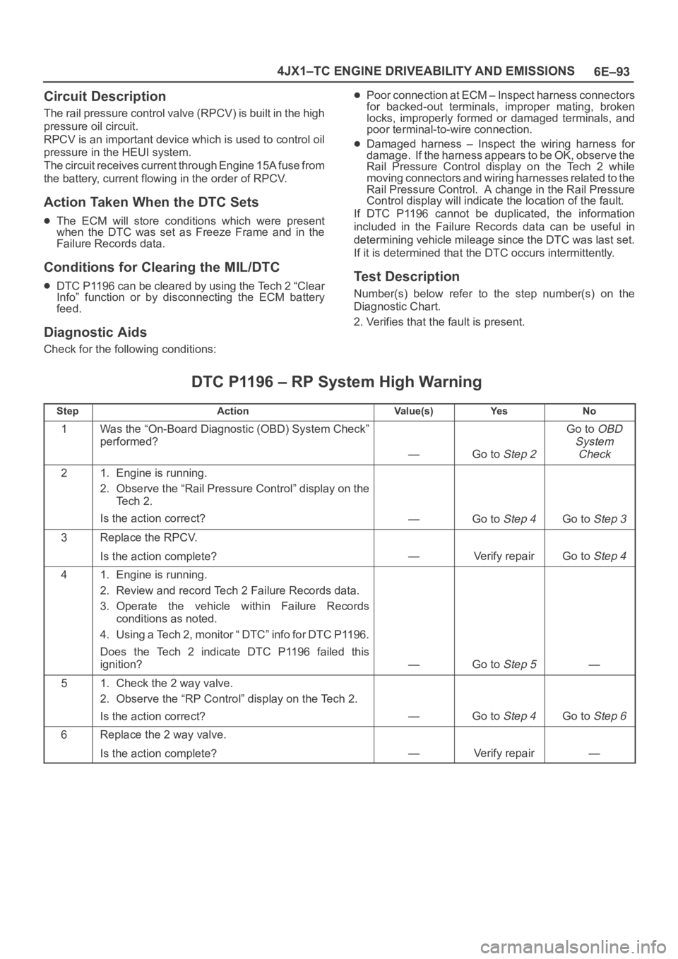
Test Description
Number(s) below refer to the step number(s) on the
Diagnostic Chart.
2. Verifies that the fault is present.
DTC P1196 – RP System High Warning
StepActionVa l u e ( s )Ye sNo
1Was the “On-Board Diagnostic (OBD) System Check”
performed?
—Go to Step 2
Go to OBD
System
Check
21. Engine is running.
2. Observe the “Rail Pressure Control” display on the
Te c h 2 .
Is the action correct?
—Go to Step 4Go to Step 3
3Replace the RPCV.
Is the action complete?
—Verify repairGo to Step 4
41. Engine is running.
2. Review and record Tech 2 Failure Records data.
3. Operate the vehicle within Failure Records
conditions as noted.
4. Using a Tech 2, monitor “ DTC” info for DTC P1196.
Does the Tech 2 indicate DTC P1196 failed this
ignition?
—Go to Step 5—
51. Check the 2 way valve.
2. Observe the “RP Control” display on the Tech 2.
Is the action correct?
—Go to Step 4Go to Step 6
6Replace the 2 way valve.
Is the action complete?
—Verify repair—