1998 OPEL FRONTERA fuse
[x] Cancel search: fusePage 1081 of 6000
6D1–2
ENGINE ELECTRICAL
Battery
General Description
There are six battery fluid caps on top of the battery.
These are covered by a paper label.
The battery is completely sealed except for the six small
vent holes on the side. These vent holes permit the
escape of small amounts of gas generated by the battery.
This type of battery has the following advantages over
conventional batteries:
1. There is no need to add water during the entire
service life of the battery.
2. The battery protects itself against overcharging.
The battery will refuse to accept an extensive charge.
(A conventional battery will accept an excessive
charge, resulting in gassing and loss of battery fluid.)
3. The battery is much less vulnerable to self discharge
than a conventional type battery.
Diagnosis
1. Visual Inspection
Inspect the battery for obvious physical damage, such as
a cracked or broken case, which would permit electrolyte
loss.
Replace the battery if obvious physical damage is
discovered during inspection.
Check for any other physical damage and correct it as
necessary.
2. Hydrometer Check
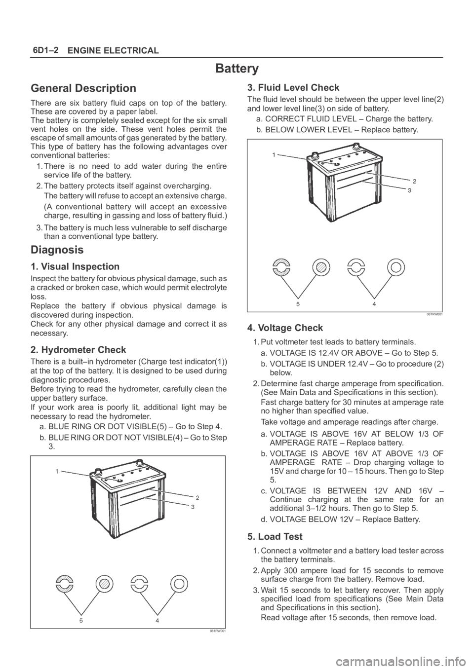
There is a built–in hydrometer (Charge test indicator(1))
at the top of the battery. It is designed to be used during
diagnostic procedures.
Before trying to read the hydrometer, carefully clean the
upper battery surface.
If your work area is poorly lit, additional light may be
necessary to read the hydrometer.
a. BLUE RING OR DOT VISIBLE(5) – Go to Step 4.
b . B L U E R I N G O R D O T N O T V I S I B L E ( 4 ) – G o t o S t e p
3.
061RW001
3. Fluid Level Check
The fluid level should be between the upper level line(2)
and lower level line(3) on side of battery.
a. CORRECT FLUID LEVEL – Charge the battery.
b. BELOW LOWER LEVEL – Replace battery.
061RW001
4. Voltage Check
1. Put voltmeter test leads to battery terminals.
a. VOLTAGE IS 12.4V OR ABOVE – Go to Step 5.
b. VOLTAGE IS UNDER 12.4V – Go to procedure (2)
below.
2. Determine fast charge amperage from specification.
(See Main Data and Specifications in this section).
Fast charge battery for 30 minutes at amperage rate
no higher than specified value.
Take voltage and amperage readings after charge.
a. VOLTAGE IS ABOVE 16V AT BELOW 1/3 OF
AMPERAGE RATE – Replace battery.
b. VOLTAGE IS ABOVE 16V AT ABOVE 1/3 OF
AMPERAGE RATE – Drop charging voltage to
15V and charge for 10 – 15 hours. Then go to Step
5.
c. VOLTAGE IS BETWEEN 12V AND 16V –
Continue charging at the same rate for an
additional 3–1/2 hours. Then go to Step 5.
d. VOLTAGE BELOW 12V – Replace Battery.
5. Load Test
1. Connect a voltmeter and a battery load tester across
the battery terminals.
2. Apply 300 ampere load for 15 seconds to remove
surface charge from the battery. Remove load.
3. Wait 15 seconds to let battery recover. Then apply
specified load from specifications (See Main Data
and Specifications in this section).
Read voltage after 15 seconds, then remove load.
Page 1118 of 6000
6E–1 ENGINE DRIVEABILITY AND EMISSIONS
ENGINE
ENGINE DRIVEABILITY AND EMISSIONS
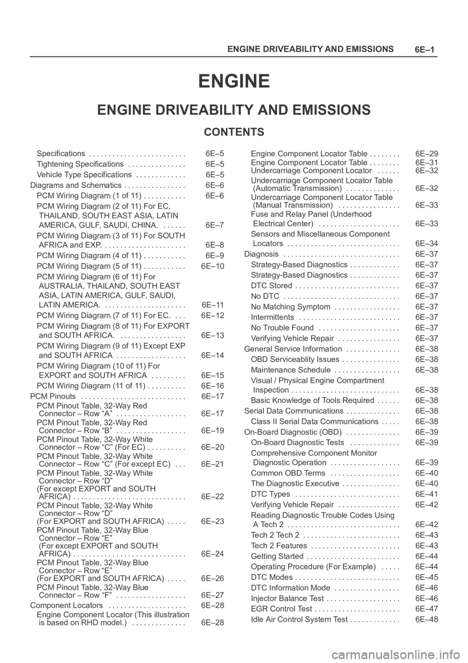
CONTENTS
Specifications 6E–5. . . . . . . . . . . . . . . . . . . . . . . . .
Tightening Specifications 6E–5. . . . . . . . . . . . . . .
Vehicle Type Specifications 6E–5. . . . . . . . . . . . .
Diagrams and Schematics 6E–6. . . . . . . . . . . . . . . .
PCM Wiring Diagram (1 of 11) 6E–6. . . . . . . . . . .
PCM Wiring Diagram (2 of 11) For EC,
THAILAND, SOUTH EAST ASIA, LATIN
AMERICA, GULF, SAUDI, CHINA. 6E–7. . . . . .
PCM Wiring Diagram (3 of 11) For SOUTH
AFRICA and EXP. 6E–8. . . . . . . . . . . . . . . . . . . . .
PCM Wiring Diagram (4 of 11) 6E–9. . . . . . . . . . .
PCM Wiring Diagram (5 of 11) 6E–10. . . . . . . . . . .
PCM Wiring Diagram (6 of 11) For
AUSTRALIA, THAILAND, SOUTH EAST
ASIA, LATIN AMERICA, GULF, SAUDI,
LATIN AMERICA. 6E–11. . . . . . . . . . . . . . . . . . . . .
PCM Wiring Diagram (7 of 11) For EC. 6E–12. . .
PCM Wiring Diagram (8 of 11) For EXPORT
and SOUTH AFRICA. 6E–13. . . . . . . . . . . . . . . . .
PCM Wiring Diagram (9 of 11) Except EXP
and SOUTH AFRICA 6E–14. . . . . . . . . . . . . . . . . .
PCM Wiring Diagram (10 of 11) For
EXPORT and SOUTH AFRICA 6E–15. . . . . . . . .
PCM Wiring Diagram (11 of 11) 6E–16. . . . . . . . . .
PCM Pinouts 6E–17. . . . . . . . . . . . . . . . . . . . . . . . . . .
PCM Pinout Table, 32-Way Red
Connector – Row “A” 6E–17. . . . . . . . . . . . . . . . . .
PCM Pinout Table, 32-Way Red
Connector – Row “B” 6E–19. . . . . . . . . . . . . . . . . .
PCM Pinout Table, 32-Way White
Connector – Row “C” (For EC) 6E–20. . . . . . . . . .
PCM Pinout Table, 32-Way White
Connector – Row “C” (For except EC) 6E–21. . .
PCM Pinout Table, 32-Way White
Connector – Row “D”
(For except EXPORT and SOUTH
AFRICA) 6E–22. . . . . . . . . . . . . . . . . . . . . . . . . . . . .
PCM Pinout Table, 32-Way White
Connector – Row “D”
(For EXPORT and SOUTH AFRICA) 6E–23. . . . .
PCM Pinout Table, 32-Way Blue
Connector – Row “E”
(For except EXPORT and SOUTH
AFRICA) 6E–24. . . . . . . . . . . . . . . . . . . . . . . . . . . . .
PCM Pinout Table, 32-Way Blue
Connector – Row “E”
(For EXPORT and SOUTH AFRICA) 6E–26. . . . .
PCM Pinout Table, 32-Way Blue
Connector – Row “F” 6E–27. . . . . . . . . . . . . . . . . .
Component Locators 6E–28. . . . . . . . . . . . . . . . . . . .
Engine Component Locator (This illustration
is based on RHD model.) 6E–28. . . . . . . . . . . . . . Engine Component Locator Table 6E–29. . . . . . . .
Engine Component Locator Table 6E–31. . . . . . . .
Undercarriage Component Locator 6E–32. . . . . .
Undercarriage Component Locator Table
(Automatic Transmission) 6E–32. . . . . . . . . . . . . .
Undercarriage Component Locator Table
(Manual Transmission) 6E–33. . . . . . . . . . . . . . . .
Fuse and Relay Panel (Underhood
Electrical Center) 6E–33. . . . . . . . . . . . . . . . . . . . .
Sensors and Miscellaneous Component
Locators 6E–34. . . . . . . . . . . . . . . . . . . . . . . . . . . . .
Diagnosis 6E–37. . . . . . . . . . . . . . . . . . . . . . . . . . . . . .
Strategy-Based Diagnostics 6E–37. . . . . . . . . . . . .
Strategy-Based Diagnostics 6E–37. . . . . . . . . . . . .
DTC Stored 6E–37
. . . . . . . . . . . . . . . . . . . . . . . . . . .
No DTC 6E–37. . . . . . . . . . . . . . . . . . . . . . . . . . . . . .
No Matching Symptom 6E–37. . . . . . . . . . . . . . . . .
Intermittents 6E–37. . . . . . . . . . . . . . . . . . . . . . . . . .
No Trouble Found 6E–37. . . . . . . . . . . . . . . . . . . . .
Verifying Vehicle Repair 6E–37. . . . . . . . . . . . . . . .
General Service Information 6E–38. . . . . . . . . . . . . .
OBD Serviceablity Issues 6E–38. . . . . . . . . . . . . . .
Maintenance Schedule 6E–38. . . . . . . . . . . . . . . . .
Visual / Physical Engine Compartment
Inspection 6E–38. . . . . . . . . . . . . . . . . . . . . . . . . . . .
Basic Knowledge of Tools Required 6E–38. . . . . .
Serial Data Communications 6E–38. . . . . . . . . . . . . .
Class II Serial Data Communications 6E–38. . . . .
On-Board Diagnostic (OBD) 6E–39. . . . . . . . . . . . . .
On-Board Diagnostic Tests 6E–39. . . . . . . . . . . . .
Comprehensive Component Monitor
Diagnostic Operation 6E–39. . . . . . . . . . . . . . . . . .
Common OBD Terms 6E–40. . . . . . . . . . . . . . . . . .
The Diagnostic Executive 6E–40. . . . . . . . . . . . . . .
DTC Types 6E–41. . . . . . . . . . . . . . . . . . . . . . . . . . .
Verifying Vehicle Repair 6E–42. . . . . . . . . . . . . . . .
Reading Diagnostic Trouble Codes Using
A Tech 2 6E–42. . . . . . . . . . . . . . . . . . . . . . . . . . . . .
Tech 2 Tech 2 6E–43. . . . . . . . . . . . . . . . . . . . . . . . .
Tech 2 Features 6E–43. . . . . . . . . . . . . . . . . . . . . . .
Getting Started 6E–44. . . . . . . . . . . . . . . . . . . . . . . .
Operating Procedure (For Example) 6E–44. . . . .
DTC Modes 6E–45. . . . . . . . . . . . . . . . . . . . . . . . . . .
DTC Information Mode 6E–46. . . . . . . . . . . . . . . . .
Injector Balance Test 6E–46. . . . . . . . . . . . . . . . . . .
EGR Control Test 6E–47. . . . . . . . . . . . . . . . . . . . . .
Idle Air Control System Test 6E–48. . . . . . . . . . . . .
Page 1146 of 6000
6E–29 ENGINE DRIVEABILITY AND EMISSIONS
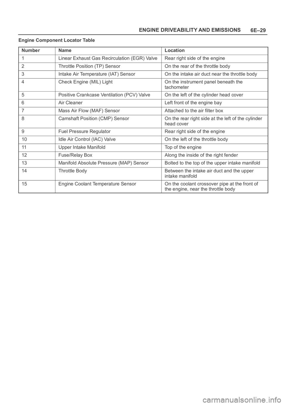
Engine Component Locator Table
Number
NameLocation
1Linear Exhaust Gas Recirculation (EGR) ValveRear right side of the engine
2Throttle Position (TP) SensorOn the rear of the throttle body
3Intake Air Temperature (IAT) SensorOn the intake air duct near the throttle body
4Check Engine (MIL) LightOn the instrument panel beneath the
tachometer
5Positive Crankcase Ventilation (PCV) ValveOn the left of the cylinder head cover
6Air CleanerLeft front of the engine bay
7Mass Air Flow (MAF) SensorAttached to the air filter box
8Camshaft Position (CMP) SensorOn the rear right side at the left of the cylinder
head cover
9Fuel Pressure RegulatorRear right side of the engine
10Idle Air Control (IAC) ValveOn the left of the throttle body
11Upper Intake ManifoldTop of the engine
12Fuse/Relay BoxAlong the inside of the right fender
13Manifold Absolute Pressure (MAP) SensorBolted to the top of the upper intake manifold
14Throttle BodyBetween the intake air duct and the upper
intake manifold
15Engine Coolant Temperature SensorOn the coolant crossover pipe at the front of
the engine, near the throttle body
Page 1148 of 6000
6E–31 ENGINE DRIVEABILITY AND EMISSIONS
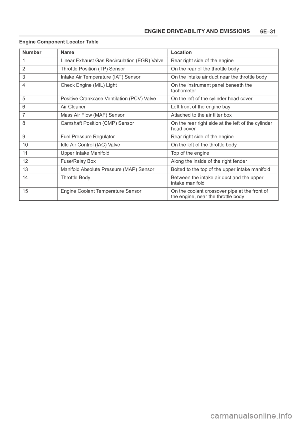
Engine Component Locator Table
Number
NameLocation
1Linear Exhaust Gas Recirculation (EGR) ValveRear right side of the engine
2Throttle Position (TP) SensorOn the rear of the throttle body
3Intake Air Temperature (IAT) SensorOn the intake air duct near the throttle body
4Check Engine (MIL) LightOn the instrument panel beneath the
tachometer
5Positive Crankcase Ventilation (PCV) ValveOn the left of the cylinder head cover
6Air CleanerLeft front of the engine bay
7Mass Air Flow (MAF) SensorAttached to the air filter box
8Camshaft Position (CMP) SensorOn the rear right side at the left of the cylinder
head cover
9Fuel Pressure RegulatorRear right side of the engine
10Idle Air Control (IAC) ValveOn the left of the throttle body
11Upper Intake ManifoldTop of the engine
12Fuse/Relay BoxAlong the inside of the right fender
13Manifold Absolute Pressure (MAP) SensorBolted to the top of the upper intake manifold
14Throttle BodyBetween the intake air duct and the upper
intake manifold
15Engine Coolant Temperature SensorOn the coolant crossover pipe at the front of
the engine, near the throttle body
Page 1150 of 6000
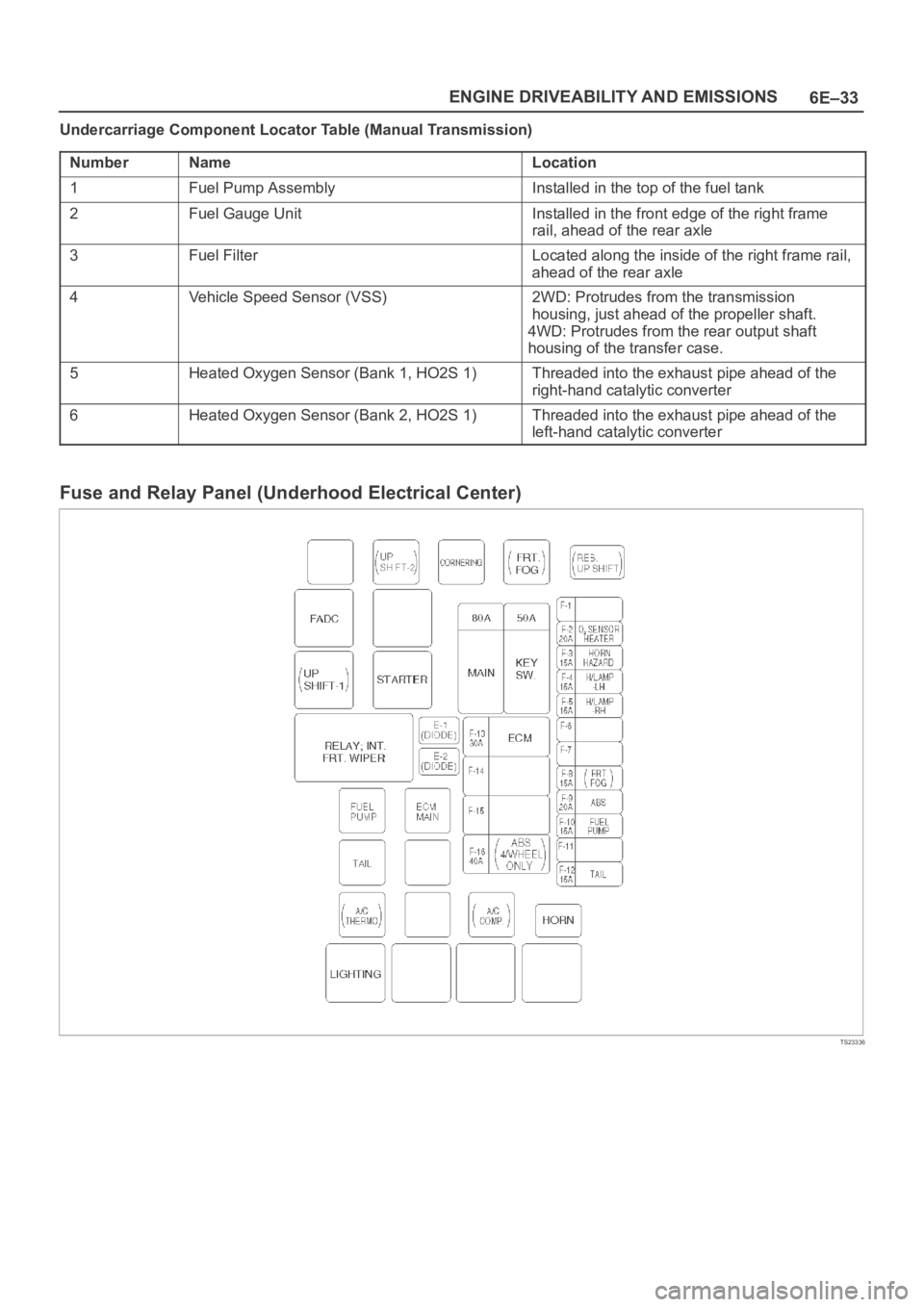
6E–33 ENGINE DRIVEABILITY AND EMISSIONS
Undercarriage Component Locator Table (Manual Transmission)
Number
NameLocation
1Fuel Pump AssemblyInstalled in the top of the fuel tank
2Fuel Gauge UnitInstalled in the front edge of the right frame
rail, ahead of the rear axle
3Fuel FilterLocated along the inside of the right frame rail,
ahead of the rear axle
4Vehicle Speed Sensor (VSS)2WD: Protrudes from the transmission
housing, just ahead of the propeller shaft.
4WD: Protrudes from the rear output shaft
housing of the transfer case.
5Heated Oxygen Sensor (Bank 1, HO2S 1)Threaded into the exhaust pipe ahead of the
right-hand catalytic converter
6Heated Oxygen Sensor (Bank 2, HO2S 1)Threaded into the exhaust pipe ahead of the
left-hand catalytic converter
Fuse and Relay Panel (Underhood Electrical Center)
TS23336
Page 1159 of 6000
6E–42
ENGINE DRIVEABILITY AND EMISSIONS
Intermittent Malfunction Indicator Lamp
In the case of an “intermittent” fault, the MIL (“Check
Engine” lamp) may illuminate and then (after three trips)
go “OFF”. However, the corresponding diagnostic trouble
code will be stored in the memory. When unexpected
diagnostic trouble codes appear, check for an intermittent
malfunction.
A diagnostic trouble code may reset. Consult the
“Diagnostic Aids” associated with the diagnostic trouble
code. A physical inspection of the applicable sub-system
most often will resolve the problem.
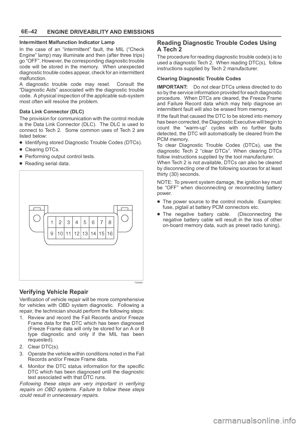
Data Link Connector (DLC)
The provision for communication with the control module
is the Data Link Connector (DLC). The DLC is used to
connect to Tech 2. Some common uses of Tech 2 are
listed below:
Identifying stored Diagnostic Trouble Codes (DTCs).
Clearing DTCs.
Performing output control tests.
Reading serial data.
TS24064
Verifying Vehicle Repair
Verification of vehicle repair will be more comprehensive
for vehicles with OBD system diagnostic. Following a
repair, the technician should perform the following steps:
1. Review and record the Fail Records and/or Freeze
Frame data for the DTC which has been diagnosed
(Freeze Frame data will only be stored for an A or B
type diagnostic and only if the MIL has been
requested).
2. Clear DTC(s).
3. Operate the vehicle within conditions noted in the Fail
Records and/or Freeze Frame data.
4. Monitor the DTC status information for the specific
DTC which has been diagnosed until the diagnostic
test associated with that DTC runs.
Following these steps are very important in verifying
repairs on OBD systems. Failure to follow these steps
could result in unnecessary repairs.
Reading Diagnostic Trouble Codes Using
A Tech 2
The procedure for reading diagnostic trouble code(s) is to
used a diagnostic Tech 2. When reading DTC(s), follow
instructions supplied by Tech 2 manufacturer.
Clearing Diagnostic Trouble Codes
IMPORTANT:Do not clear DTCs unless directed to do
so by the service information provided for each diagnostic
procedure. When DTCs are cleared, the Freeze Frame
and Failure Record data which may help diagnose an
intermittent fault will also be erased from memory.
If the fault that caused the DTC to be stored into memory
has been corrected, the Diagnostic Executive will begin to
count the “warm-up” cycles with no further faults
detected, the DTC will automatically be cleared from the
PCM memory.
To clear Diagnostic Trouble Codes (DTCs), use the
diagnostic Tech 2 “clear DTCs”. When clearing DTCs
follow instructions supplied by the tool manufacturer.
When Tech 2 is not available, DTCs can also be cleared
by disconnecting
one of the following sources for at least
thirty (30) seconds.
NOTE: To prevent system damage, the ignition key must
be “OFF” when disconnecting or reconnecting battery
power.
The power source to the control module. Examples:
fuse, pigtail at battery PCM connectors etc.
The negative battery cable. (Disconnecting the
negative battery cable will result in the loss of other
on-board memory data, such as preset radio tuning).
Page 1173 of 6000
6E–56
ENGINE DRIVEABILITY AND EMISSIONS
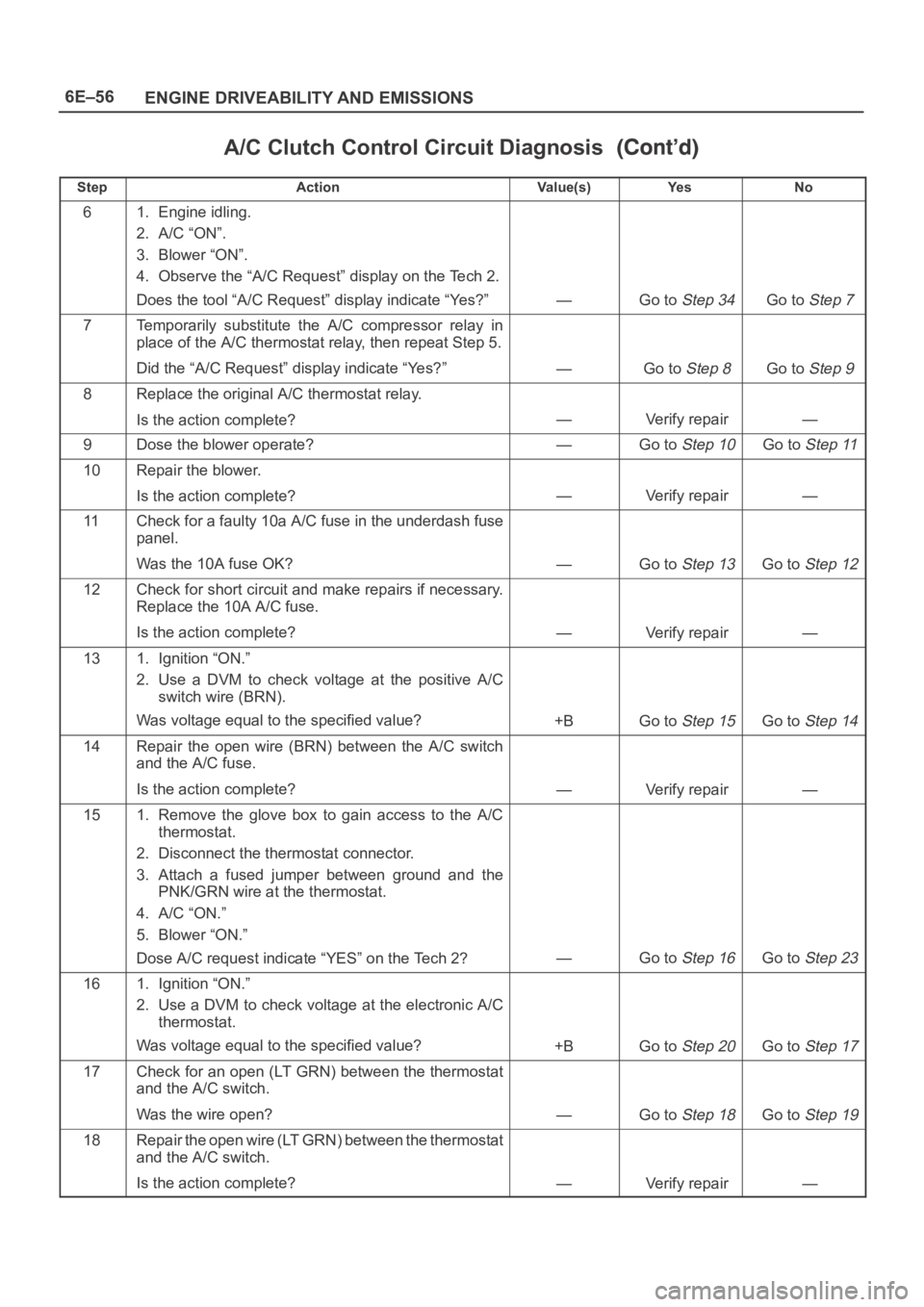
A/C Clutch Control Circuit Diagnosis
StepNo Ye s Va l u e ( s ) Action
61. Engine idling.
2. A/C “ON”.
3. Blower “ON”.
4. Observe the “A/C Request” display on the Tech 2.
Does the tool “A/C Request” display indicate “Yes?”
—Go to Step 34Go to Step 7
7Temporarily substitute the A/C compressor relay in
place of the A/C thermostat relay, then repeat Step 5.
Did the “A/C Request” display indicate “Yes?”
—Go to Step 8Go to Step 9
8Replace the original A/C thermostat relay.
Is the action complete?
—Verify repair—
9Dose the blower operate?—Go to Step 10Go to Step 11
10Repair the blower.
Is the action complete?
—Verify repair—
11Check for a faulty 10a A/C fuse in the underdash fuse
panel.
Was the 10A fuse OK?
—Go to Step 13Go to Step 12
12Check for short circuit and make repairs if necessary.
Replace the 10A A/C fuse.
Is the action complete?
—Verify repair—
131. Ignition “ON.”
2. Use a DVM to check voltage at the positive A/C
switch wire (BRN).
Was voltage equal to the specified value?
+BGo to Step 15Go to Step 14
14Repair the open wire (BRN) between the A/C switch
and the A/C fuse.
Is the action complete?
—Verify repair—
151. Remove the glove box to gain access to the A/C
thermostat.
2. Disconnect the thermostat connector.
3. Attach a fused jumper between ground and the
PNK/GRN wire at the thermostat.
4. A/C “ON.”
5. Blower “ON.”
Dose A/C request indicate “YES” on the Tech 2?
—Go to Step 16Go to Step 23
161. Ignition “ON.”
2. Use a DVM to check voltage at the electronic A/C
thermostat.
Was voltage equal to the specified value?
+BGo to Step 20Go to Step 17
17Check for an open (LT GRN) between the thermostat
and the A/C switch.
Was the wire open?
—Go to Step 18Go to Step 19
18Repair the open wire (LT GRN) between the thermostat
and the A/C switch.
Is the action complete?
—Verify repair—
Page 1174 of 6000
6E–57 ENGINE DRIVEABILITY AND EMISSIONS
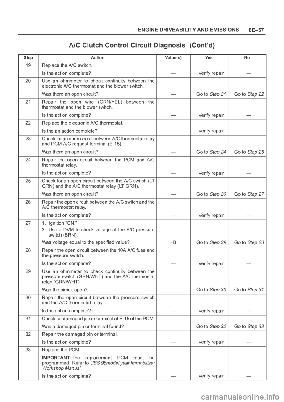
A/C Clutch Control Circuit Diagnosis
StepNo Ye s Va l u e ( s ) Action
19Replace the A/C switch.
Is the action complete?
—Verify repair—
20Use an ohmmeter to check continuity between the
electronic A/C thermostat and the blower switch.
Was there an open circuit?
—Go to Step 21Go to Step 22
21Repair the open wire (GRN/YEL) between the
thermostat and the blower switch.
Is the action complete?
—Verify repair—
22Replace the electronic A/C thermostat.
Is the an action complete?
—Verify repair—
23Check for an open circuit between A/C thermostat relay
and PCM A/C request terminal (E-15).
Was there an open circuit?
—Go to Step 24Go to Step 25
24Repair the open circuit between the PCM and A/C
thermostat relay.
Is the action complete?
—Verify repair—
25Check for an open circuit between the A/C switch (LT
GRN) and the A/C thermostat relay (LT GRN).
Was there an open circuit?
—Go to Step 26Go to Step 27
26Repair the open circuit between the A/C switch and the
A/C thermostat relay.
Is the action complete?
—Verify repair—
271. Ignition “ON.”
2. Use a DVM to check voltage at the A/C pressure
switch (BRN).
Was voltage equal to the specified value?
+BGo to Step 29Go to Step 28
28Repair the open circuit between the 10A A/C fuse and
the pressure switch.
Is the action complete?
—Verify repair—
29Use an ohmmeter to check continuity between the
pressure switch (GRN/WHT) and the A/C thermostat
relay (GRN/WHT).
Was the circuit open?
—Go to Step 30Go to Step 31
30Repair the open circuit between the pressure switch
and the A/C thermostat relay.
Is the action complete?
—Verify repair—
31Check for damaged pin or terminal at E-15 of the PCM.
Was a damaged pin or terminal found?
—Go to Step 32Go to Step 33
32Repair the damaged pin or terminal.
Is the action complete?
—Verify repair—
33Replace the PCM.
IMPORTANT:The replacement PCM must be
programmed. Refer to
UBS 98model year Immobilizer
Workshop Manual.
Is the action complete?—Verify repair—