1998 OPEL FRONTERA fuel pressure
[x] Cancel search: fuel pressurePage 1214 of 6000
6E–97 ENGINE DRIVEABILITY AND EMISSIONS
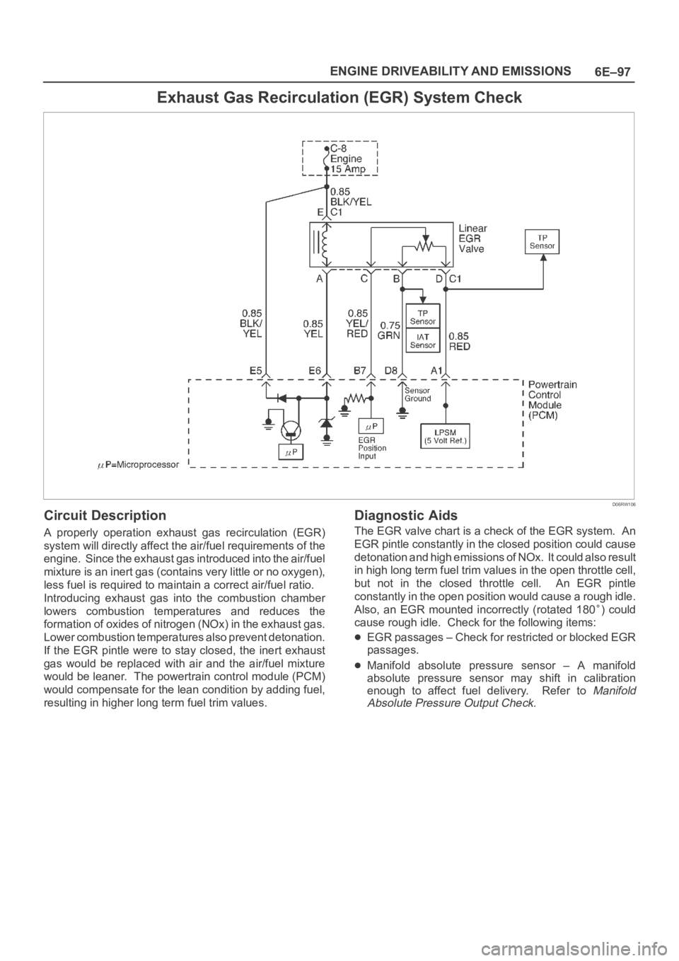
Exhaust Gas Recirculation (EGR) System Check
D06RW106
Circuit Description
A properly operation exhaust gas recirculation (EGR)
system will directly affect the air/fuel requirements of the
engine. Since the exhaust gas introduced into the air/fuel
mixture is an inert gas (contains very little or no oxygen),
less fuel is required to maintain a correct air/fuel ratio.
Introducing exhaust gas into the combustion chamber
lowers combustion temperatures and reduces the
formation of oxides of nitrogen (NOx) in the exhaust gas.
Lower combustion temperatures also prevent detonation.
If the EGR pintle were to stay closed, the inert exhaust
gas would be replaced with air and the air/fuel mixture
would be leaner. The powertrain control module (PCM)
would compensate for the lean condition by adding fuel,
resulting in higher long term fuel trim values.
Diagnostic Aids
The EGR valve chart is a check of the EGR system. An
EGR pintle constantly in the closed position could cause
detonation and high emissions of NOx. It could also result
in high long term fuel trim values in the open throttle cell,
but not in the closed throttle cell. An EGR pintle
constantly in the open position would cause a rough idle.
Also, an EGR mounted incorrectly (rotated 180
) could
cause rough idle. Check for the following items:
EGR passages – Check for restricted or blocked EGR
passages.
Manifold absolute pressure sensor – A manifold
absolute pressure sensor may shift in calibration
enough to affect fuel delivery. Refer to
Manifold
Absolute Pressure Output Check.
Page 1221 of 6000
6E–104
ENGINE DRIVEABILITY AND EMISSIONS
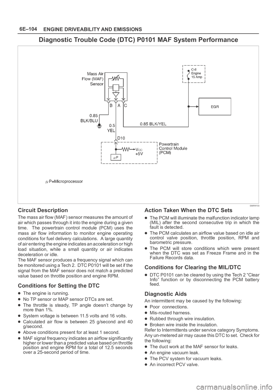
Diagnostic Trouble Code (DTC) P0101 MAF System Performance
D06RW103
Circuit Description
The mass air flow (MAF) sensor measures the amount of
air which passes through it into the engine during a given
time. The powertrain control module (PCM) uses the
mass air flow information to monitor engine operating
conditions for fuel delivery calculations. A large quantity
of air entering the engine indicates an acceleration or high
load situation, while a small quantity or air indicates
deceleration or idle.
The MAF sensor produces a frequency signal which can
be monitored using a Tech 2. DTC P0101 will be set if the
signal from the MAF sensor does not match a predicted
value based on throttle position and engine RPM.
Conditions for Setting the DTC
The engine is running.
No TP sensor or MAP sensor DTCs are set.
The throttle is steady, TP angle doesn’t change by
more than 1%.
System voltage is between 11.5 volts and 16 volts.
Calculated air flow is between 25 g/second and 40
g/second.
Above conditions present for at least 1 second.
MAF signal frequency indicates an airflow significantly
higher or lower than a predicted value based on throttle
position and engine RPM for a total of 12.5 seconds
over a 25-second period of time.
Action Taken When the DTC Sets
The PCM will illuminate the malfunction indicator lamp
(MIL) after the second consecutive trip in which the
fault is detected.
The PCM calculates an airflow value based on idle air
control valve position, throttle position, RPM and
barometric pressure.
The PCM will store conditions which were present
when the DTC was set as Freeze Frame and in the
Failure Records data.
Conditions for Clearing the MIL/DTC
DTC P0101 can be cleared by using the Tech 2 “Clear
Info” function or by disconnecting the PCM battery
feed.
Diagnostic Aids
An intermittent may be caused by the following:
Poor connections.
Mis-routed harness.
Rubbed through wire insulation.
Broken wire inside the insulation.
Refer to Intermittents under service category Symptoms.
Any un-metered air may cause this DTC to set. Check for
the following:
The duct work at the MAF sensor for leaks.
An engine vacuum leak.
The PCV system for vacuum leaks.
An incorrect PCV valve.
Page 1224 of 6000
6E–107 ENGINE DRIVEABILITY AND EMISSIONS
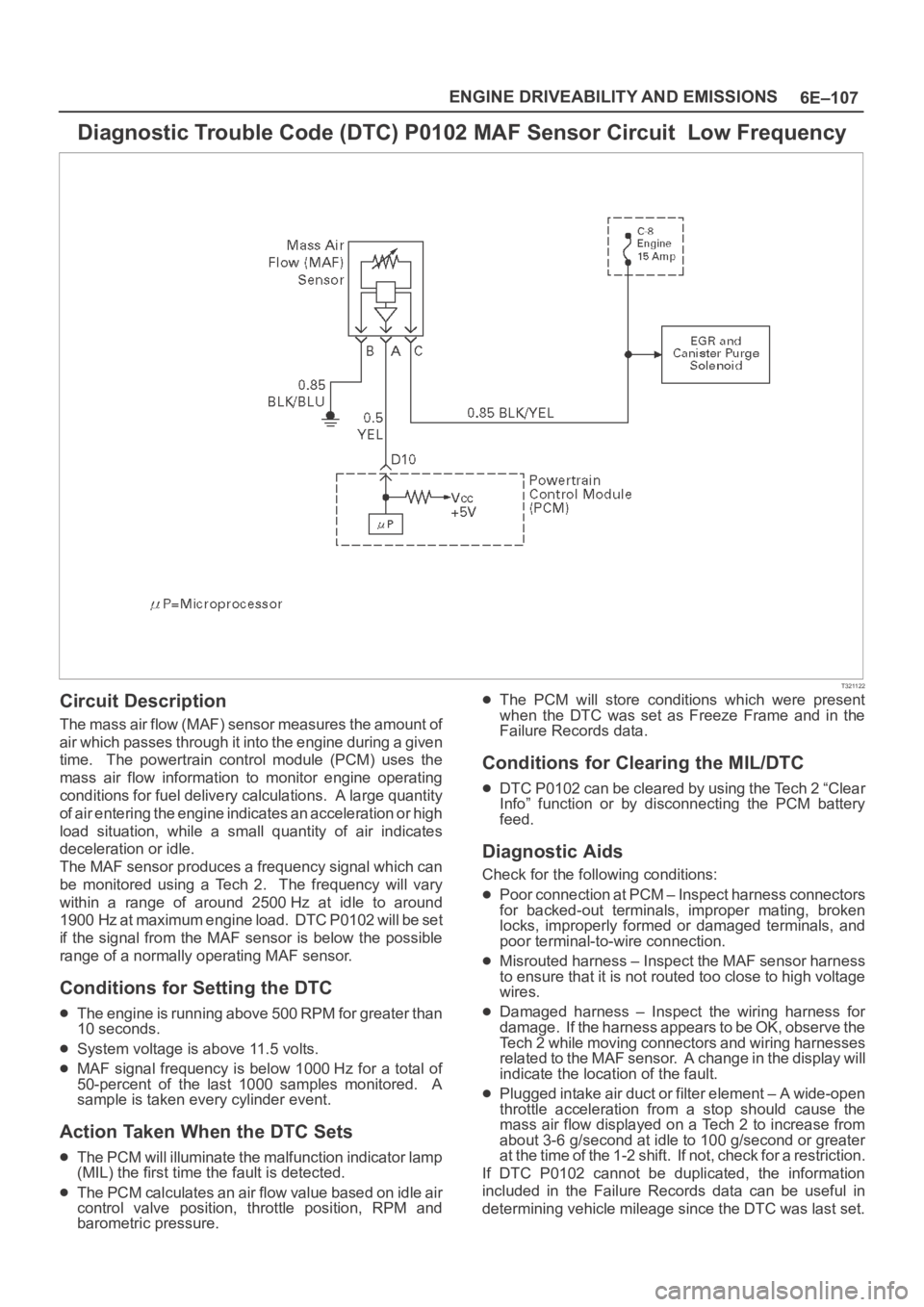
Diagnostic Trouble Code (DTC) P0102 MAF Sensor Circuit Low Frequency
T321122
Circuit Description
The mass air flow (MAF) sensor measures the amount of
air which passes through it into the engine during a given
time. The powertrain control module (PCM) uses the
mass air flow information to monitor engine operating
conditions for fuel delivery calculations. A large quantity
of air entering the engine indicates an acceleration or high
load situation, while a small quantity of air indicates
deceleration or idle.
The MAF sensor produces a frequency signal which can
be monitored using a Tech 2. The frequency will vary
within a range of around 2500 Hz at idle to around
1900 Hz at maximum engine load. DTC P0102 will be set
if the signal from the MAF sensor is below the possible
range of a normally operating MAF sensor.
Conditions for Setting the DTC
The engine is running above 500 RPM for greater than
10 seconds.
System voltage is above 11.5 volts.
MAF signal frequency is below 1000 Hz for a total of
50-percent of the last 1000 samples monitored. A
sample is taken every cylinder event.
Action Taken When the DTC Sets
The PCM will illuminate the malfunction indicator lamp
(MIL) the first time the fault is detected.
The PCM calculates an air flow value based on idle air
control valve position, throttle position, RPM and
barometric pressure.
The PCM will store conditions which were present
when the DTC was set as Freeze Frame and in the
Failure Records data.
Conditions for Clearing the MIL/DTC
DTC P0102 can be cleared by using the Tech 2 “Clear
Info” function or by disconnecting the PCM battery
feed.
Diagnostic Aids
Check for the following conditions:
Poor connection at PCM – Inspect harness connectors
for backed-out terminals, improper mating, broken
locks, improperly formed or damaged terminals, and
poor terminal-to-wire connection.
Misrouted harness – Inspect the MAF sensor harness
to ensure that it is not routed too close to high voltage
wires.
Damaged harness – Inspect the wiring harness for
damage. If the harness appears to be OK, observe the
Tech 2 while moving connectors and wiring harnesses
related to the MAF sensor. A change in the display will
indicate the location of the fault.
Plugged intake air duct or filter element – A wide-open
throttle acceleration from a stop should cause the
mass air flow displayed on a Tech 2 to increase from
about 3-6 g/second at idle to 100 g/second or greater
at the time of the 1-2 shift. If not, check for a restriction.
If DTC P0102 cannot be duplicated, the information
included in the Failure Records data can be useful in
determining vehicle mileage since the DTC was last set.
Page 1227 of 6000
6E–110
ENGINE DRIVEABILITY AND EMISSIONS
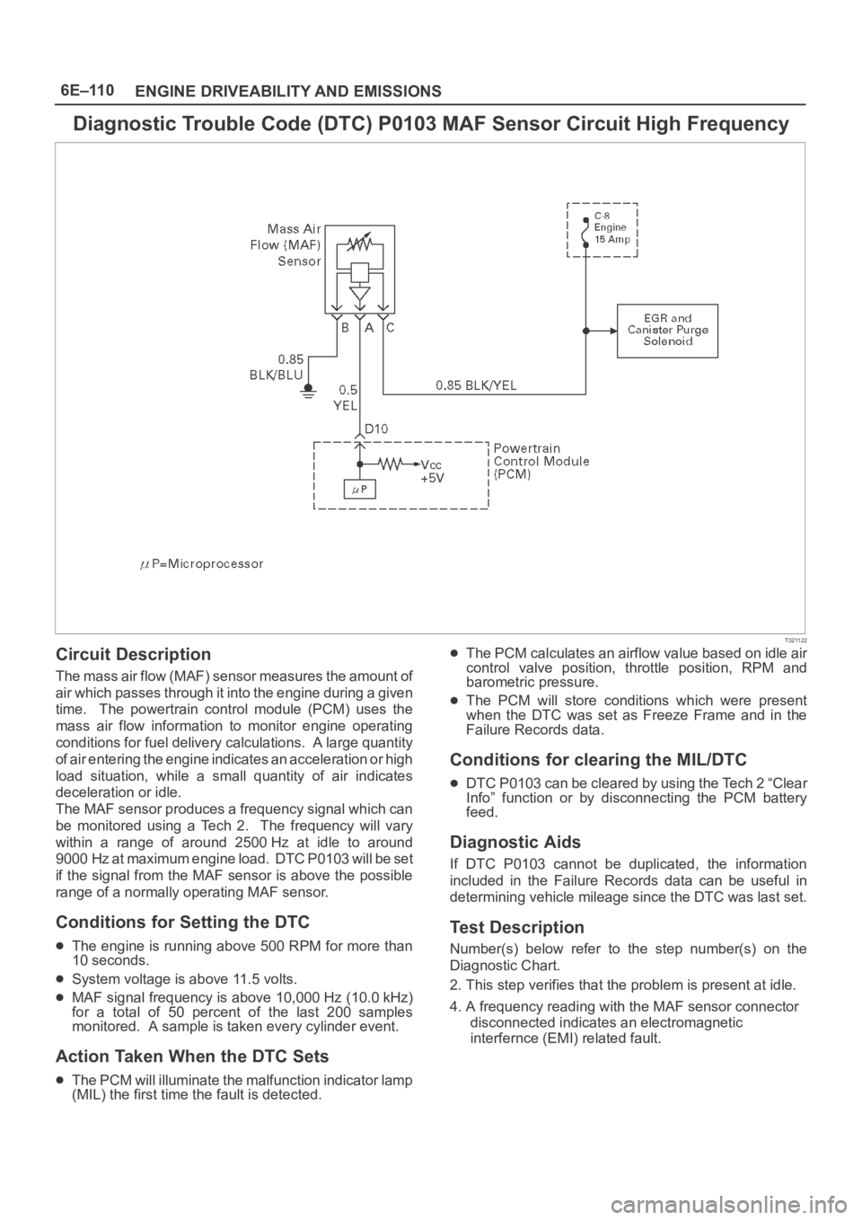
Diagnostic Trouble Code (DTC) P0103 MAF Sensor Circuit High Frequency
T321122
Circuit Description
The mass air flow (MAF) sensor measures the amount of
air which passes through it into the engine during a given
time. The powertrain control module (PCM) uses the
mass air flow information to monitor engine operating
conditions for fuel delivery calculations. A large quantity
of air entering the engine indicates an acceleration or high
load situation, while a small quantity of air indicates
deceleration or idle.
The MAF sensor produces a frequency signal which can
be monitored using a Tech 2. The frequency will vary
within a range of around 2500 Hz at idle to around
9000 Hz at maximum engine load. DTC P0103 will be set
if the signal from the MAF sensor is above the possible
range of a normally operating MAF sensor.
Conditions for Setting the DTC
The engine is running above 500 RPM for more than
10 seconds.
System voltage is above 11.5 volts.
MAF signal frequency is above 10,000 Hz (10.0 kHz)
for a total of 50 percent of the last 200 samples
monitored. A sample is taken every cylinder event.
Action Taken When the DTC Sets
The PCM will illuminate the malfunction indicator lamp
(MIL) the first time the fault is detected.
The PCM calculates an airflow value based on idle air
control valve position, throttle position, RPM and
barometric pressure.
The PCM will store conditions which were present
when the DTC was set as Freeze Frame and in the
Failure Records data.
Conditions for clearing the MIL/DTC
DTC P0103 can be cleared by using the Tech 2 “Clear
Info” function or by disconnecting the PCM battery
feed.
Diagnostic Aids
If DTC P0103 cannot be duplicated, the information
included in the Failure Records data can be useful in
determining vehicle mileage since the DTC was last set.
Test Description
Number(s) below refer to the step number(s) on the
Diagnostic Chart.
2. This step verifies that the problem is present at idle.
4. A frequency reading with the MAF sensor connector
disconnected indicates an electromagnetic
interfernce (EMI) related fault.
Page 1256 of 6000
6E–139 ENGINE DRIVEABILITY AND EMISSIONS
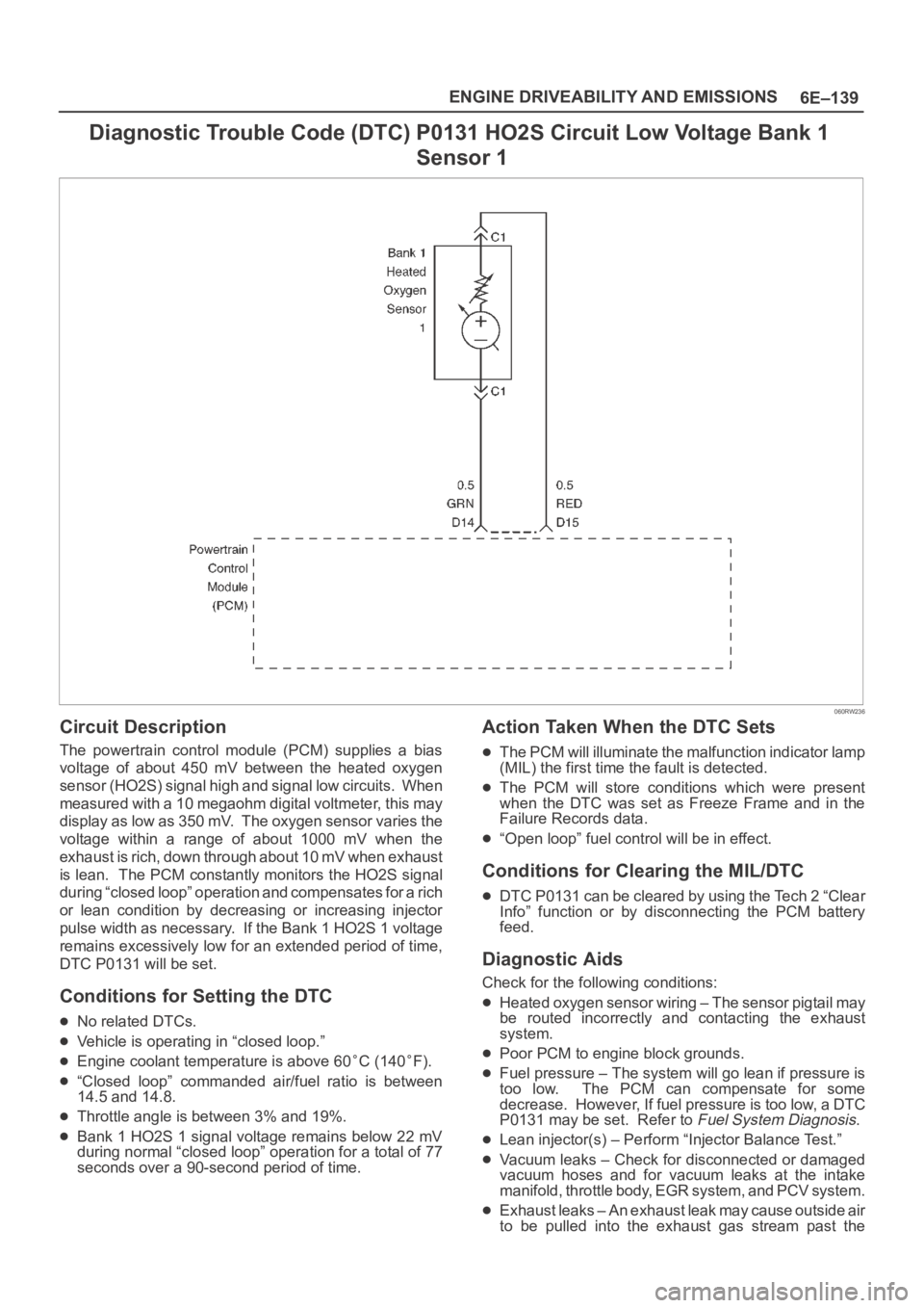
Diagnostic Trouble Code (DTC) P0131 HO2S Circuit Low Voltage Bank 1
Sensor 1
060RW236
Circuit Description
The powertrain control module (PCM) supplies a bias
voltage of about 450 mV between the heated oxygen
sensor (HO2S) signal high and signal low circuits. When
measured with a 10 megaohm digital voltmeter, this may
display as low as 350 mV. The oxygen sensor varies the
voltage within a range of about 1000 mV when the
exhaust is rich, down through about 10 mV when exhaust
is lean. The PCM constantly monitors the HO2S signal
during “closed loop” operation and compensates for a rich
or lean condition by decreasing or increasing injector
pulse width as necessary. If the Bank 1 HO2S 1 voltage
remains excessively low for an extended period of time,
DTC P0131 will be set.
Conditions for Setting the DTC
No related DTCs.
Vehicle is operating in “closed loop.”
Engine coolant temperature is above 60C (140F).
“Closed loop” commanded air/fuel ratio is between
14.5 and 14.8.
Throttle angle is between 3% and 19%.
Bank 1 HO2S 1 signal voltage remains below 22 mV
during normal “closed loop” operation for a total of 77
seconds over a 90-second period of time.
Action Taken When the DTC Sets
The PCM will illuminate the malfunction indicator lamp
(MIL) the first time the fault is detected.
The PCM will store conditions which were present
when the DTC was set as Freeze Frame and in the
Failure Records data.
“Open loop” fuel control will be in effect.
Conditions for Clearing the MIL/DTC
DTC P0131 can be cleared by using the Tech 2 “Clear
Info” function or by disconnecting the PCM battery
feed.
Diagnostic Aids
Check for the following conditions:
Heated oxygen sensor wiring – The sensor pigtail may
be routed incorrectly and contacting the exhaust
system.
Poor PCM to engine block grounds.
Fuel pressure – The system will go lean if pressure is
too low. The PCM can compensate for some
decrease. However, If fuel pressure is too low, a DTC
P0131 may be set. Refer to
Fuel System Diagnosis.
Lean injector(s) – Perform “Injector Balance Test.”
Vacuum leaks – Check for disconnected or damaged
vacuum hoses and for vacuum leaks at the intake
manifold, throttle body, EGR system, and PCV system.
Exhaust leaks – An exhaust leak may cause outside air
to be pulled into the exhaust gas stream past the
Page 1259 of 6000
6E–142
ENGINE DRIVEABILITY AND EMISSIONS
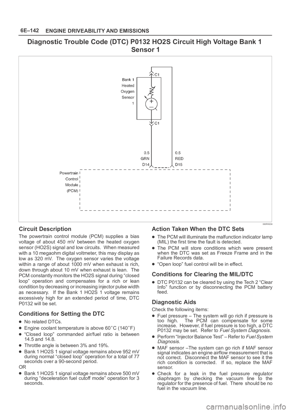
Diagnostic Trouble Code (DTC) P0132 HO2S Circuit High Voltage Bank 1
Sensor 1
060RW236
Circuit Description
The powertrain control module (PCM) supplies a bias
voltage of about 450 mV between the heated oxygen
sensor (HO2S) signal and low circuits. When measured
with a 10 megaohm digital voltmeter, this may display as
low as 320 mV. The oxygen sensor varies the voltage
within a range of about 1000 mV when exhaust is rich,
down through about 10 mV when exhaust is lean. The
PCM constantly monitors the HO2S signal during “closed
loop” operation and compensates for a rich or lean
condition by decreasing or increasing injector pulse width
as necessary. If the Bank 1 HO2S 1 voltage remains
excessively high for an extended period of time, DTC
P0132 will be set.
Conditions for Setting the DTC
No related DTCs.
Engine coolant temperature is above 60C (140F)
“Closed loop” commanded air/fuel ratio is between
14.5 and 14.8.
Throttle angle is between 3% and 19%.
Bank 1 HO2S 1 signal voltage remains above 952 mV
during normal “closed loop” operation for a total of 77
seconds over a 90-second period.
OR
Bank 1 HO2S 1 signal voltage remains above 500 mV
during “deceleration fuel cutoff mode” operation for 3
seconds.
Action Taken When the DTC Sets
The PCM will illuminate the malfunction indicator lamp
(MIL) the first time the fault is detected.
The PCM will store conditions which were present
when the DTC was set as Freeze Frame and in the
Failure Records data.
“Open loop” fuel control will be in effect.
Conditions for Clearing the MIL/DTC
DTC P0132 can be cleared by using the Tech 2 “Clear
Info” function or by disconnecting the PCM battery
feed.
Diagnostic Aids
Check the following items:
Fuel pressure – The system will go rich if pressure is
too high. The PCM can compensate for some
increase. However, if fuel pressure is too high, a DTC
P0132 may be set. Refer to
Fuel System Diagnosis.
Perform “Injector Balance Test” – Refer to Fuel System
Diagnosis.
MAF sensor –The system can go rich if MAF sensor
signal indicates an engine airflow measurement that is
not correct. Disconnect the MAF sensor to see it the
rich condition is corrected. If so, replace the MAF
sensor.
Check for a leak in the fuel pressure regulator
diaphragm by checking the vacuum line to the
regulator for the presence of fuel. There should be no
fuel in the vacuum line.
Page 1265 of 6000
6E–148
ENGINE DRIVEABILITY AND EMISSIONS
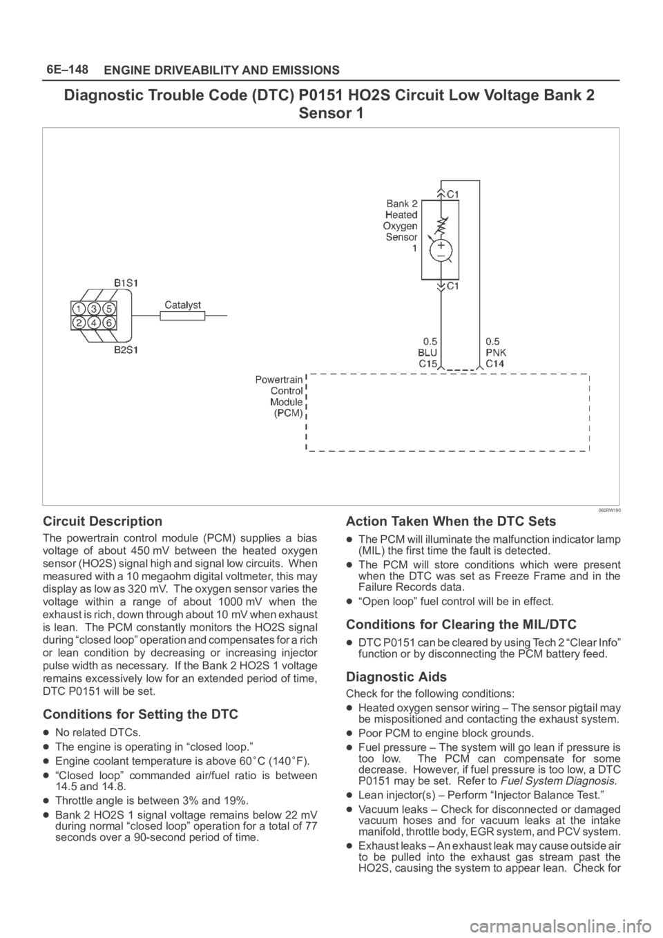
Diagnostic Trouble Code (DTC) P0151 HO2S Circuit Low Voltage Bank 2
Sensor 1
060RW190
Circuit Description
The powertrain control module (PCM) supplies a bias
voltage of about 450 mV between the heated oxygen
sensor (HO2S) signal high and signal low circuits. When
measured with a 10 megaohm digital voltmeter, this may
display as low as 320 mV. The oxygen sensor varies the
voltage within a range of about 1000 mV when the
exhaust is rich, down through about 10 mV when exhaust
is lean. The PCM constantly monitors the HO2S signal
during “closed loop” operation and compensates for a rich
or lean condition by decreasing or increasing injector
pulse width as necessary. If the Bank 2 HO2S 1 voltage
remains excessively low for an extended period of time,
DTC P0151 will be set.
Conditions for Setting the DTC
No related DTCs.
The engine is operating in “closed loop.”
Engine coolant temperature is above 60C (140F).
“Closed loop” commanded air/fuel ratio is between
14.5 and 14.8.
Throttle angle is between 3% and 19%.
Bank 2 HO2S 1 signal voltage remains below 22 mV
during normal “closed loop” operation for a total of 77
seconds over a 90-second period of time.
Action Taken When the DTC Sets
The PCM will illuminate the malfunction indicator lamp
(MIL) the first time the fault is detected.
The PCM will store conditions which were present
when the DTC was set as Freeze Frame and in the
Failure Records data.
“Open loop” fuel control will be in effect.
Conditions for Clearing the MIL/DTC
DTC P0151 can be cleared by using Tech 2 “Clear Info”
function or by disconnecting the PCM battery feed.
Diagnostic Aids
Check for the following conditions:
Heated oxygen sensor wiring – The sensor pigtail may
be mispositioned and contacting the exhaust system.
Poor PCM to engine block grounds.
Fuel pressure – The system will go lean if pressure is
too low. The PCM can compensate for some
decrease. However, if fuel pressure is too low, a DTC
P0151 may be set. Refer to
Fuel System Diagnosis.
Lean injector(s) – Perform “Injector Balance Test.”
Vacuum leaks – Check for disconnected or damaged
vacuum hoses and for vacuum leaks at the intake
manifold, throttle body, EGR system, and PCV system.
Exhaust leaks – An exhaust leak may cause outside air
to be pulled into the exhaust gas stream past the
HO2S, causing the system to appear lean. Check for
Page 1268 of 6000
6E–151 ENGINE DRIVEABILITY AND EMISSIONS
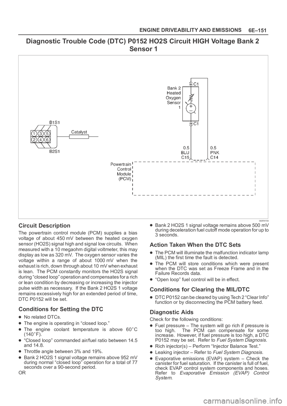
Diagnostic Trouble Code (DTC) P0152 HO2S Circuit HIGH Voltage Bank 2
Sensor 1
060RW190
Circuit Description
The powertrain control module (PCM) supplies a bias
voltage of about 450 mV between the heated oxygen
sensor (HO2S) signal high and signal low circuits. When
measured with a 10 megaohm digital voltmeter, this may
display as low as 320 mV. The oxygen sensor varies the
voltage within a range of about 1000 mV when the
exhaust is rich, down through about 10 mV when exhaust
is lean. The PCM constantly monitors the HO2S signal
during “closed loop” operation and compensates for a rich
or lean condition by decreasing or increasing the injector
pulse width as necessary. If the Bank 2 HO2S 1 voltage
remains excessively high for an extended period of time,
DTC P0152 will be set.
Conditions for Setting the DTC
No related DTCs.
The engine is operating in “closed loop.”
The engine coolant temperature is above 60C
(140
F).
“Closed loop” commanded air/fuel ratio between 14.5
and 14.8.
Throttle angle between 3% and 19%.
Bank 2 HO2S 1 signal voltage remains above 952 mV
during normal “closed loop” operation for a total of 77
seconds over a 90-second period.
OR
Bank 2 HO2S 1 signal voltage remains above 500 mV
during deceleration fuel cutoff mode operation for up to
3 seconds.
Action Taken When the DTC Sets
The PCM will illuminate the malfunction indicator lamp
(MIL) the first time the fault is detected.
The PCM will store conditions which were present
when the DTC was set as Freeze Frame and in the
Failure Records data.
“Open loop” fuel control will be in effect.
Conditions for Clearing the MIL/DTC
DTC P0152 can be cleared by using Tech 2 “Clear Info”
function or by disconnecting the PCM battery feed.
Diagnostic Aids
Check for the following conditions:
Fuel pressure – The system will go rich if pressure is
too high. The PCM can compensate for some
increase. However, if fuel pressure is too high, a DTC
P0152 may be set. Refer to
Fuel System Diagnosis.
Rich injector(s) – Perform “Injector Balance Test.”
Leaking injector – Refer to Fuel System Diagnosis.
Evaporative emissions (EVAP) system – Check the
canister for fuel saturation. If the canister is full of fuel,
check EVAP control system components and hoses.
Refer to
Evaporative Emission (EVAP) Control
System
.