1998 OPEL FRONTERA fuel pressure
[x] Cancel search: fuel pressurePage 1119 of 6000
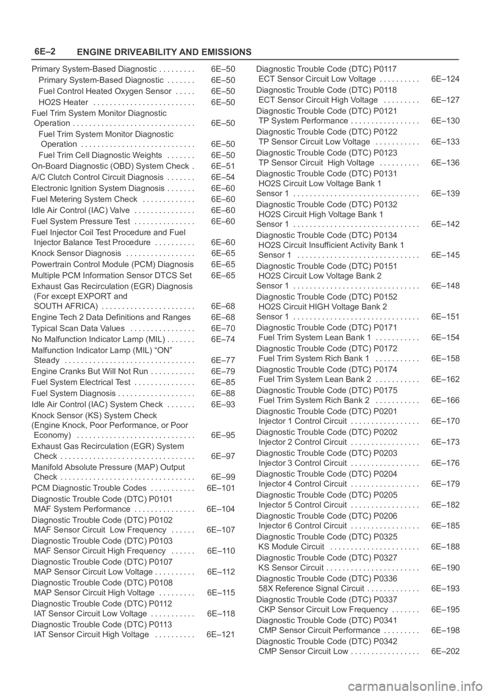
6E–2
ENGINE DRIVEABILITY AND EMISSIONS
Primary System-Based Diagnostic 6E–50. . . . . . . . .
Primary System-Based Diagnostic 6E–50. . . . . . .
Fuel Control Heated Oxygen Sensor 6E–50. . . . .
HO2S Heater 6E–50. . . . . . . . . . . . . . . . . . . . . . . . .
Fuel Trim System Monitor Diagnostic
Operation 6E–50. . . . . . . . . . . . . . . . . . . . . . . . . . . . . .
Fuel Trim System Monitor Diagnostic
Operation 6E–50. . . . . . . . . . . . . . . . . . . . . . . . . . . .
Fuel Trim Cell Diagnostic Weights 6E–50. . . . . . .
On-Board Diagnostic (OBD) System Check 6E–51.
A/C Clutch Control Circuit Diagnosis 6E–54. . . . . . .
Electronic Ignition System Diagnosis 6E–60. . . . . . .
Fuel Metering System Check 6E–60. . . . . . . . . . . . .
Idle Air Control (IAC) Valve 6E–60. . . . . . . . . . . . . . .
Fuel System Pressure Test 6E–60. . . . . . . . . . . . . . .
Fuel Injector Coil Test Procedure and Fuel
Injector Balance Test Procedure 6E–60. . . . . . . . . .
Knock Sensor Diagnosis 6E–65. . . . . . . . . . . . . . . . .
Powertrain Control Module (PCM) Diagnosis 6E–65
Multiple PCM Information Sensor DTCS Set 6E–65
Exhaust Gas Recirculation (EGR) Diagnosis
(For except EXPORT and
SOUTH AFRICA) 6E–68. . . . . . . . . . . . . . . . . . . . . . .
Engine Tech 2 Data Definitions and Ranges 6E–68
Typical Scan Data Values 6E–70. . . . . . . . . . . . . . . .
No Malfunction Indicator Lamp (MIL) 6E–74. . . . . . .
Malfunction Indicator Lamp (MIL) “ON”
Steady 6E–77. . . . . . . . . . . . . . . . . . . . . . . . . . . . . . . .
Engine Cranks But Will Not Run 6E–79. . . . . . . . . . .
Fuel System Electrical Test 6E–85. . . . . . . . . . . . . . .
Fuel System Diagnosis 6E–88. . . . . . . . . . . . . . . . . . .
Idle Air Control (IAC) System Check 6E–93. . . . . . .
Knock Sensor (KS) System Check
(Engine Knock, Poor Performance, or Poor
Economy) 6E–95. . . . . . . . . . . . . . . . . . . . . . . . . . . . .
Exhaust Gas Recirculation (EGR) System
Check 6E–97. . . . . . . . . . . . . . . . . . . . . . . . . . . . . . . . .
Manifold Absolute Pressure (MAP) Output
Check 6E–99. . . . . . . . . . . . . . . . . . . . . . . . . . . . . . . . .
PCM Diagnostic Trouble Codes 6E–101. . . . . . . . . . .
Diagnostic Trouble Code (DTC) P0101
MAF System Performance 6E–104. . . . . . . . . . . . . . .
Diagnostic Trouble Code (DTC) P0102
MAF Sensor Circuit Low Frequency 6E–107. . . . . .
Diagnostic Trouble Code (DTC) P0103
MAF Sensor Circuit High Frequency 6E–110. . . . . .
Diagnostic Trouble Code (DTC) P0107
MAP Sensor Circuit Low Voltage 6E–112. . . . . . . . . .
Diagnostic Trouble Code (DTC) P0108
MAP Sensor Circuit High Voltage 6E–115. . . . . . . . .
Diagnostic Trouble Code (DTC) P0112
IAT Sensor Circuit Low Voltage 6E–118. . . . . . . . . . .
Diagnostic Trouble Code (DTC) P0113
IAT Sensor Circuit High Voltage 6E–121. . . . . . . . . . Diagnostic Trouble Code (DTC) P0117
ECT Sensor Circuit Low Voltage 6E–124. . . . . . . . . .
Diagnostic Trouble Code (DTC) P0118
ECT Sensor Circuit High Voltage 6E–127. . . . . . . . .
Diagnostic Trouble Code (DTC) P0121
TP System Performance 6E–130. . . . . . . . . . . . . . . . .
Diagnostic Trouble Code (DTC) P0122
TP Sensor Circuit Low Voltage 6E–133. . . . . . . . . . .
Diagnostic Trouble Code (DTC) P0123
TP Sensor Circuit High Voltage 6E–136. . . . . . . . . .
Diagnostic Trouble Code (DTC) P0131
HO2S Circuit Low Voltage Bank 1
Sensor 1 6E–139. . . . . . . . . . . . . . . . . . . . . . . . . . . . . . .
Diagnostic Trouble Code (DTC) P0132
HO2S Circuit High Voltage Bank 1
Sensor 1 6E–142. . . . . . . . . . . . . . . . . . . . . . . . . . . . . . .
Diagnostic Trouble Code (DTC) P0134
HO2S Circuit Insufficient Activity Bank 1
Sensor 1 6E–145. . . . . . . . . . . . . . . . . . . . . . . . . . . . . .
Diagnostic Trouble Code (DTC) P0151
HO2S Circuit Low Voltage Bank 2
Sensor 1 6E–148. . . . . . . . . . . . . . . . . . . . . . . . . . . . . . .
Diagnostic Trouble Code (DTC) P0152
HO2S Circuit HIGH Voltage Bank 2
Sensor 1 6E–151. . . . . . . . . . . . . . . . . . . . . . . . . . . . . . .
Diagnostic Trouble Code (DTC) P0171
Fuel Trim System Lean Bank 1 6E–154. . . . . . . . . . .
Diagnostic Trouble Code (DTC) P0172
Fuel Trim System Rich Bank 1 6E–158. . . . . . . . . . .
Diagnostic Trouble Code (DTC) P0174
Fuel Trim System Lean Bank 2 6E–162. . . . . . . . . . .
Diagnostic Trouble Code (DTC) P0175
Fuel Trim System Rich Bank 2 6E–166. . . . . . . . . . .
Diagnostic Trouble Code (DTC) P0201
Injector 1 Control Circuit 6E–170. . . . . . . . . . . . . . . . .
Diagnostic Trouble Code (DTC) P0202
Injector 2 Control Circuit 6E–173. . . . . . . . . . . . . . . . .
Diagnostic Trouble Code (DTC) P0203
Injector 3 Control Circuit 6E–176. . . . . . . . . . . . . . . . .
Diagnostic Trouble Code (DTC) P0204
Injector 4 Control Circuit 6E–179. . . . . . . . . . . . . . . . .
Diagnostic Trouble Code (DTC) P0205
Injector 5 Control Circuit 6E–182. . . . . . . . . . . . . . . . .
Diagnostic Trouble Code (DTC) P0206
Injector 6 Control Circuit 6E–185. . . . . . . . . . . . . . . . .
Diagnostic Trouble Code (DTC) P0325
KS Module Circuit 6E–188. . . . . . . . . . . . . . . . . . . . . .
Diagnostic Trouble Code (DTC) P0327
KS Sensor Circuit 6E–190. . . . . . . . . . . . . . . . . . . . . . .
Diagnostic Trouble Code (DTC) P0336
58X Reference Signal Circuit 6E–193. . . . . . . . . . . . .
Diagnostic Trouble Code (DTC) P0337
CKP Sensor Circuit Low Frequency 6E–195. . . . . . .
Diagnostic Trouble Code (DTC) P0341
CMP Sensor Circuit Performance 6E–198. . . . . . . . .
Diagnostic Trouble Code (DTC) P0342
CMP Sensor Circuit Low 6E–202. . . . . . . . . . . . . . . . .
Page 1120 of 6000
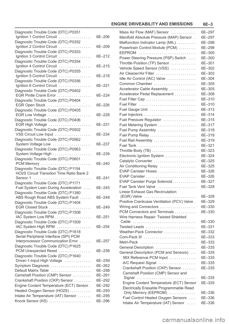
6E–3 ENGINE DRIVEABILITY AND EMISSIONS
Diagnostic Trouble Code (DTC) P0351
Ignition 1 Control Circuit 6E–206. . . . . . . . . . . . . . . . .
Diagnostic Trouble Code (DTC) P0352
Ignition 2 Control Circuit 6E–209. . . . . . . . . . . . . . . . .
Diagnostic Trouble Code (DTC) P0353
Ignition 3 Control Circuit 6E–212. . . . . . . . . . . . . . . . .
Diagnostic Trouble Code (DTC) P0354
Ignition 4 Control Circuit 6E–215. . . . . . . . . . . . . . . . .
Diagnostic Trouble Code (DTC) P0355
Ignition 5 Control Circuit 6E–218. . . . . . . . . . . . . . . . .
Diagnostic Trouble Code (DTC) P0356
Ignition 6 Control Circuit 6E–221. . . . . . . . . . . . . . . . .
Diagnostic Trouble Code (DTC) P0402
EGR Pintle Crank Error 6E–224. . . . . . . . . . . . . . . . . .
Diagnostic Trouble Code (DTC) P0404
EGR Open Stuck 6E–226. . . . . . . . . . . . . . . . . . . . . . .
Diagnostic Trouble Code (DTC) P0405
EGR Low Voltage 6E–228. . . . . . . . . . . . . . . . . . . . . . .
Diagnostic Trouble Code (DTC) P0406
EGR High Voltage 6E–231. . . . . . . . . . . . . . . . . . . . . .
Diagnostic Trouble Code (DTC) P0502
VSS Circuit Low Input 6E–234. . . . . . . . . . . . . . . . . . .
Diagnostic Trouble Code (DTC) P0562
System Voltage Low 6E–237. . . . . . . . . . . . . . . . . . . .
Diagnostic Trouble Code (DTC) P0563
System Voltage High 6E–239. . . . . . . . . . . . . . . . . . . .
Diagnostic Trouble Code (DTC) P0601
PCM Memory 6E–240. . . . . . . . . . . . . . . . . . . . . . . . . .
Diagnostic Trouble Code (DTC) P1154
HO2S Circuit Transition Time Ratio Bank 2
Sensor 1 6E–241. . . . . . . . . . . . . . . . . . . . . . . . . . . . . .
Diagnostic Trouble Code (DTC) P1171
Fuel System Lean During Acceleration 6E–245. . . .
Diagnostic Trouble Code (DTC) P1380
ABS Rough Road ABS System Fault 6E–248. . . . . .
Diagnostic Trouble Code (DTC) P1404
EGR Closed Stuck 6E–249. . . . . . . . . . . . . . . . . . . . . .
Diagnostic Trouble Code (DTC) P1508
IAC System Low RPM 6E–251. . . . . . . . . . . . . . . . . . .
Diagnostic Trouble Code (DTC) P1509
IAC System High RPM 6E–254. . . . . . . . . . . . . . . . . .
Diagnostic Trouble Code (DTC) P1618
Serial Peripheral Interface (SPI) PCM
Interprocessor Communication Error 6E–257. . . . . .
Diagnostic Trouble Code (DTC) P1625
PCM Unexpected Reset 6E–258. . . . . . . . . . . . . . . . .
Diagnostic Trouble Code (DTC) P1640
Driver-1-Input High Voltage 6E–259. . . . . . . . . . . . . .
Symptom Diagnosis 6E–262. . . . . . . . . . . . . . . . . . . . .
Default Matrix Table 6E–288. . . . . . . . . . . . . . . . . . . . .
Camshaft Position (CMP) Sensor 6E–291. . . . . . . . . .
Crankshaft Position (CKP) Sensor 6E–292. . . . . . . . .
Engine Coolant Temperature (ECT) Sensor 6E–292.
Heated Oxygen Sensor (HO2S) 6E–293. . . . . . . . . . .
Intake Air Temperature (IAT) Sensor 6E–295. . . . . . .
Knock Sensor (KS) 6E–296. . . . . . . . . . . . . . . . . . . . . . Mass Air Flow (MAF) Sensor 6E–297. . . . . . . . . . . . .
Manifold Absolute Pressure (MAP) Sensor 6E–297.
Malfunction Indicator Lamp (MIL) 6E–298. . . . . . . . . .
Powertrain Control Module (PCM) 6E–298. . . . . . . . .
EEPROM 6E–300. . . . . . . . . . . . . . . . . . . . . . . . . . . . . .
Power Steering Pressure (PSP) Switch 6E–300
. . . .
Throttle Position (TP) Sensor 6E–301. . . . . . . . . . . . .
Vehicle Speed Sensor (VSS) 6E–302. . . . . . . . . . . . .
Air Cleaner/Air Filter 6E–303. . . . . . . . . . . . . . . . . . . . .
Idle Air Control (IAC) Valve 6E–304. . . . . . . . . . . . . . .
Common Chamber 6E–305. . . . . . . . . . . . . . . . . . . . . .
Accelerator Cable Assembly 6E–305. . . . . . . . . . . . . .
Accelerator Pedal Replacement 6E–308. . . . . . . . . . .
Fuel Filter Cap 6E–310. . . . . . . . . . . . . . . . . . . . . . . . . .
Fuel Filter 6E–310. . . . . . . . . . . . . . . . . . . . . . . . . . . . . .
Fuel Gauge Unit 6E–313. . . . . . . . . . . . . . . . . . . . . . . .
Fuel Injectors 6E–314. . . . . . . . . . . . . . . . . . . . . . . . . . .
Fuel Pressure Regulator 6E–315. . . . . . . . . . . . . . . . .
Fuel Metering System 6E–317. . . . . . . . . . . . . . . . . . . .
Fuel Pump Assembly 6E–318. . . . . . . . . . . . . . . . . . . .
Fuel Pump Relay 6E–319. . . . . . . . . . . . . . . . . . . . . . . .
Fuel Rail Assembly 6E–319. . . . . . . . . . . . . . . . . . . . . .
Fuel Tank 6E–321. . . . . . . . . . . . . . . . . . . . . . . . . . . . . .
Throttle Body (TB) 6E–323. . . . . . . . . . . . . . . . . . . . . . .
Electronic Ignition System 6E–324. . . . . . . . . . . . . . . .
Catalytic Converter 6E–325. . . . . . . . . . . . . . . . . . . . . .
Air Conditioning Relay 6E–325. . . . . . . . . . . . . . . . . . .
EVAP Canister Hoses 6E–326. . . . . . . . . . . . . . . . . . . .
EVAP Canister 6E–326. . . . . . . . . . . . . . . . . . . . . . . . . .
EVAP Canister Purge Solenoid 6E–327. . . . . . . . . . . .
Fuel Tank Vent Valve 6E–328. . . . . . . . . . . . . . . . . . . .
Linear Exhaust Gas Recirculation
(EGR) Valve 6E–328. . . . . . . . . . . . . . . . . . . . . . . . . . .
Positive Crankcase Ventilation (PCV) Valve 6E–329.
Wiring and Connectors 6E–330. . . . . . . . . . . . . . . . . . .
PCM Connectors and Terminals 6E–330. . . . . . . . . . .
Wire Harness Repair: Twisted Shielded
Cable 6E–330. . . . . . . . . . . . . . . . . . . . . . . . . . . . . . . . .
Twisted Leads 6E–331. . . . . . . . . . . . . . . . . . . . . . . . . .
Weather-Pack Connector 6E–332. . . . . . . . . . . . . . . . .
Com-Pack III 6E–333. . . . . . . . . . . . . . . . . . . . . . . . . . .
Metri-Pack 6E–333. . . . . . . . . . . . . . . . . . . . . . . . . . . . .
General Description 6E–335. . . . . . . . . . . . . . . . . . . . .
General Description (PCM and Sensors) 6E–335. . .
58X Reference PCM Input 6E–335. . . . . . . . . . . . . .
A/C Request Signal 6E–335. . . . . . . . . . . . . . . . . . . .
Crankshaft Position (CKP) Sensor 6E–335. . . . . . .
Camshaft Position (CMP) Sensor and
Signal 6E–335. . . . . . . . . . . . . . . . . . . . . . . . . . . . . . .
Engine Coolant Temperature (ECT) Sensor 6E–335
Electrically Erasable Programmable Read
Only Memory (EEPROM) 6E–336. . . . . . . . . . . . . .
Fuel Control Heated Oxygen Sensors 6E–336. . . .
Intake Air Temperature (IAT) Sensor 6E–336. . . . .
Page 1121 of 6000
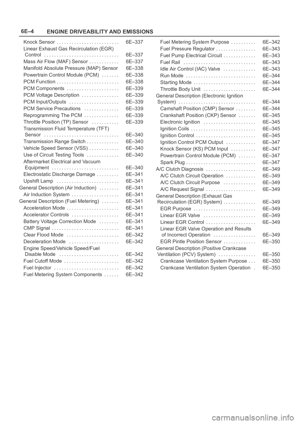
6E–4
ENGINE DRIVEABILITY AND EMISSIONS
Knock Sensor 6E–337. . . . . . . . . . . . . . . . . . . . . . . . .
Linear Exhaust Gas Recirculation (EGR)
Control 6E–337. . . . . . . . . . . . . . . . . . . . . . . . . . . . . .
Mass Air Flow (MAF) Sensor 6E–337. . . . . . . . . . . .
Manifold Absolute Pressure (MAP) Sensor 6E–338
Powertrain Control Module (PCM) 6E–338. . . . . . .
PCM Function 6E–338. . . . . . . . . . . . . . . . . . . . . . . . .
PCM Components 6E–339. . . . . . . . . . . . . . . . . . . . .
PCM Voltage Description 6E–339. . . . . . . . . . . . . . .
PCM Input/Outputs 6E–339. . . . . . . . . . . . . . . . . . . .
PCM Service Precautions 6E–339. . . . . . . . . . . . . .
Reprogramming The PCM 6E–339. . . . . . . . . . . . . .
Throttle Position (TP) Sensor 6E–339. . . . . . . . . . .
Transmission Fluid Temperature (TFT)
Sensor 6E–340. . . . . . . . . . . . . . . . . . . . . . . . . . . . . .
Transmission Range Switch 6E–340. . . . . . . . . . . . .
Vehicle Speed Sensor (VSS) 6E–340. . . . . . . . . . . .
Use of Circuit Testing Tools 6E–340. . . . . . . . . . . . .
Aftermarket Electrical and Vacuum
Equipment 6E–340. . . . . . . . . . . . . . . . . . . . . . . . . . .
Electrostatic Discharge Damage 6E–341. . . . . . . . .
Upshift Lamp 6E–341. . . . . . . . . . . . . . . . . . . . . . . . .
General Description (Air Induction) 6E–341. . . . . . . .
Air Induction System 6E–341. . . . . . . . . . . . . . . . . . .
General Description (Fuel Metering) 6E–341. . . . . . .
Acceleration Mode 6E–341. . . . . . . . . . . . . . . . . . . . .
Accelerator Controls 6E–341. . . . . . . . . . . . . . . . . . .
Battery Voltage Correction Mode 6E–341. . . . . . . .
CMP Signal 6E–341. . . . . . . . . . . . . . . . . . . . . . . . . . .
Clear Flood Mode 6E–342. . . . . . . . . . . . . . . . . . . . .
Deceleration Mode 6E–342. . . . . . . . . . . . . . . . . . . .
Engine Speed/Vehicle Speed/Fuel
Disable Mode 6E–342. . . . . . . . . . . . . . . . . . . . . . . .
Fuel Cutoff Mode 6E–342. . . . . . . . . . . . . . . . . . . . . .
Fuel Injector 6E–342. . . . . . . . . . . . . . . . . . . . . . . . . .
Fuel Metering System Components 6E–342. . . . . . Fuel Metering System Purpose 6E–342. . . . . . . . . .
Fuel Pressure Regulator 6E–343. . . . . . . . . . . . . . . .
Fuel Pump Electrical Circuit 6E–343. . . . . . . . . . . . .
Fuel Rail 6E–343. . . . . . . . . . . . . . . . . . . . . . . . . . . . .
Idle Air Control (IAC) Valve 6E–343. . . . . . . . . . . . .
Run Mode 6E–344. . . . . . . . . . . . . . . . . . . . . . . . . . . .
Starting Mode 6E–344. . . . . . . . . . . . . . . . . . . . . . . . .
Throttle Body Unit 6E–344. . . . . . . . . . . . . . . . . . . . .
General Description (Electronic Ignition
System) 6E–344. . . . . . . . . . . . . . . . . . . . . . . . . . . . . . .
Camshaft Position (CMP) Sensor 6E–344. . . . . . . .
Crankshaft Position (CKP) Sensor 6E–345. . . . . . .
Electronic Ignition 6E–345. . . . . . . . . . . . . . . . . . . . .
Ignition Coils 6E–345. . . . . . . . . . . . . . . . . . . . . . . . . .
Ignition Control 6E–345. . . . . . . . . . . . . . . . . . . . . . . .
Ignition Control PCM Output 6E–347. . . . . . . . . . . .
Knock Sensor (KS) PCM Input 6E–347
. . . . . . . . . .
Powertrain Control Module (PCM) 6E–347. . . . . . .
Spark Plug 6E–347. . . . . . . . . . . . . . . . . . . . . . . . . . . .
A/C Clutch Diagnosis 6E–349. . . . . . . . . . . . . . . . . . . .
A/C Clutch Circuit Operation 6E–349. . . . . . . . . . . .
A/C Clutch Circuit Purpose 6E–349. . . . . . . . . . . . .
A/C Request Signal 6E–349. . . . . . . . . . . . . . . . . . . .
General Description (Exhaust Gas
Recirculation (EGR) System) 6E–349. . . . . . . . . . . . .
EGR Purpose 6E–349. . . . . . . . . . . . . . . . . . . . . . . . .
Linear EGR Valve 6E–349. . . . . . . . . . . . . . . . . . . . .
Linear EGR Control 6E–349. . . . . . . . . . . . . . . . . . . .
Linear EGR Valve Operation and Results
of Incorrect Operation 6E–349. . . . . . . . . . . . . . . . .
EGR Pintle Position Sensor 6E–350. . . . . . . . . . . . .
General Description (Positive Crankcase
Ventilation (PCV) System) 6E–350. . . . . . . . . . . . . . .
Crankcase Ventilation System Purpose 6E–350. . .
Crankcase Ventilation System Operation 6E–350.
Page 1122 of 6000
6E–5 ENGINE DRIVEABILITY AND EMISSIONS
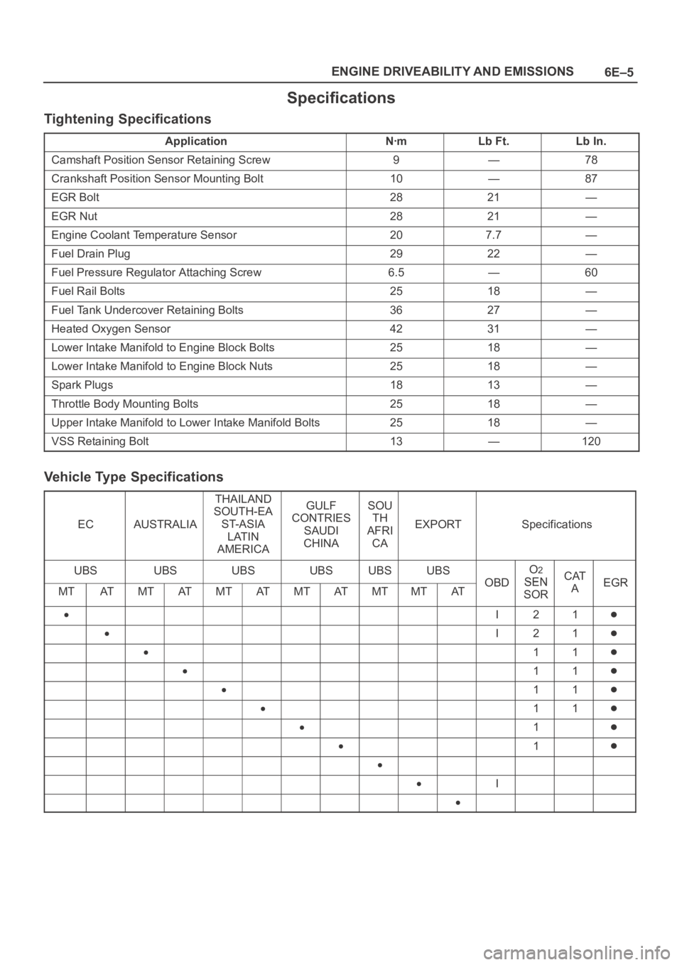
Specifications
Tightening Specifications
ApplicationNꞏmLb Ft.Lb In.
Camshaft Position Sensor Retaining Screw9—78
Crankshaft Position Sensor Mounting Bolt10—87
EGR Bolt2821—
EGR Nut2821—
Engine Coolant Temperature Sensor207.7—
Fuel Drain Plug2922—
Fuel Pressure Regulator Attaching Screw6.5—60
Fuel Rail Bolts2518—
Fuel Tank Undercover Retaining Bolts3627—
Heated Oxygen Sensor4231—
Lower Intake Manifold to Engine Block Bolts2518—
Lower Intake Manifold to Engine Block Nuts2518—
Spark Plugs1813—
Throttle Body Mounting Bolts2518—
Upper Intake Manifold to Lower Intake Manifold Bolts2518—
VSS Retaining Bolt13—120
Vehicle Type Specifications
ECAUSTRALIA
THAILAND
SOUTH-EA
ST-ASIA
LATIN
AMERICAGULF
CONTRIES
SAUDI
CHINASOU
TH
AFRI
CA
EXPORTSpecifications
UBSUBSUBSUBSUBSUBS
OBD
O2
SENCATEGRMTATMTATMTATMTATMTMTATOBDSEN
SORAEGR
I21
I21
11
11
11
11
1
1
I
Page 1141 of 6000
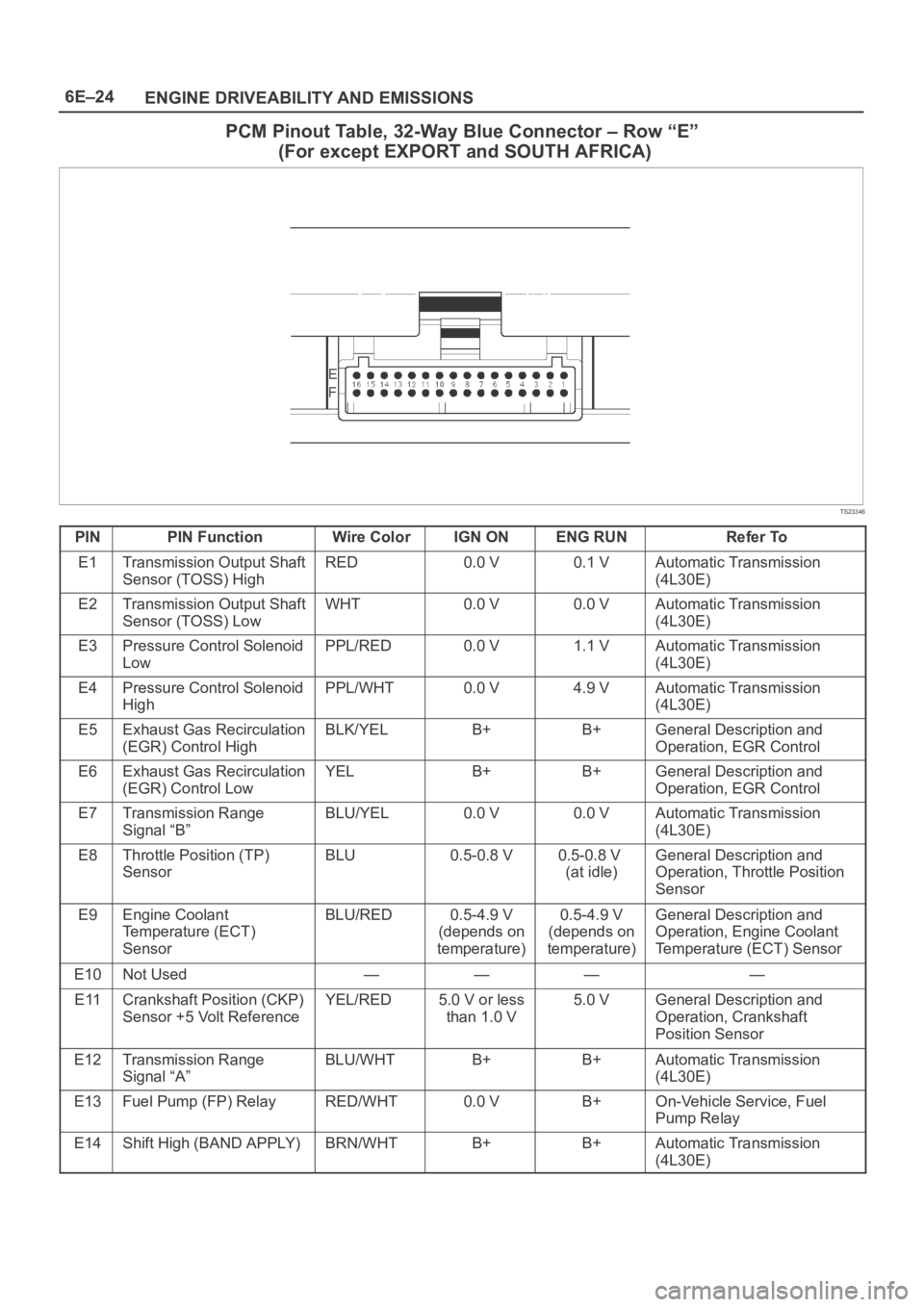
6E–24
ENGINE DRIVEABILITY AND EMISSIONS
PCM Pinout Table, 32-Way Blue Connector – Row “E”
(For except EXPORT and SOUTH AFRICA)
TS23346
PINPIN FunctionWire ColorIGN ONENG RUNRefer To
E1Transmission Output Shaft
Sensor (TOSS) HighRED0.0 V0.1 VAutomatic Transmission
(4L30E)
E2Transmission Output Shaft
Sensor (TOSS) LowWHT0.0 V0.0 VAutomatic Transmission
(4L30E)
E3Pressure Control Solenoid
LowPPL/RED0.0 V1.1 VAutomatic Transmission
(4L30E)
E4Pressure Control Solenoid
HighPPL/WHT0.0 V4.9 VAutomatic Transmission
(4L30E)
E5Exhaust Gas Recirculation
(EGR) Control HighBLK/YELB+B+General Description and
Operation, EGR Control
E6Exhaust Gas Recirculation
(EGR) Control LowYELB+B+General Description and
Operation, EGR Control
E7Transmission Range
Signal “B”BLU/YEL0.0 V0.0 VAutomatic Transmission
(4L30E)
E8Throttle Position (TP)
SensorBLU0.5-0.8 V0.5-0.8 V
(at idle)General Description and
Operation, Throttle Position
Sensor
E9Engine Coolant
Temperature (ECT)
SensorBLU/RED0.5-4.9 V
(depends on
temperature)0.5-4.9 V
(depends on
temperature)General Description and
Operation, Engine Coolant
Temperature (ECT) Sensor
E10Not Used————
E11Crankshaft Position (CKP)
Sensor +5 Volt ReferenceYEL/RED5.0 V or less
than 1.0 V5.0 VGeneral Description and
Operation, Crankshaft
Position Sensor
E12Transmission Range
Signal “A”BLU/WHTB+B+Automatic Transmission
(4L30E)
E13Fuel Pump (FP) RelayRED/WHT0.0 VB+On-Vehicle Service, Fuel
Pump Relay
E14Shift High (BAND APPLY)BRN/WHTB+B+Automatic Transmission
(4L30E)
Page 1143 of 6000
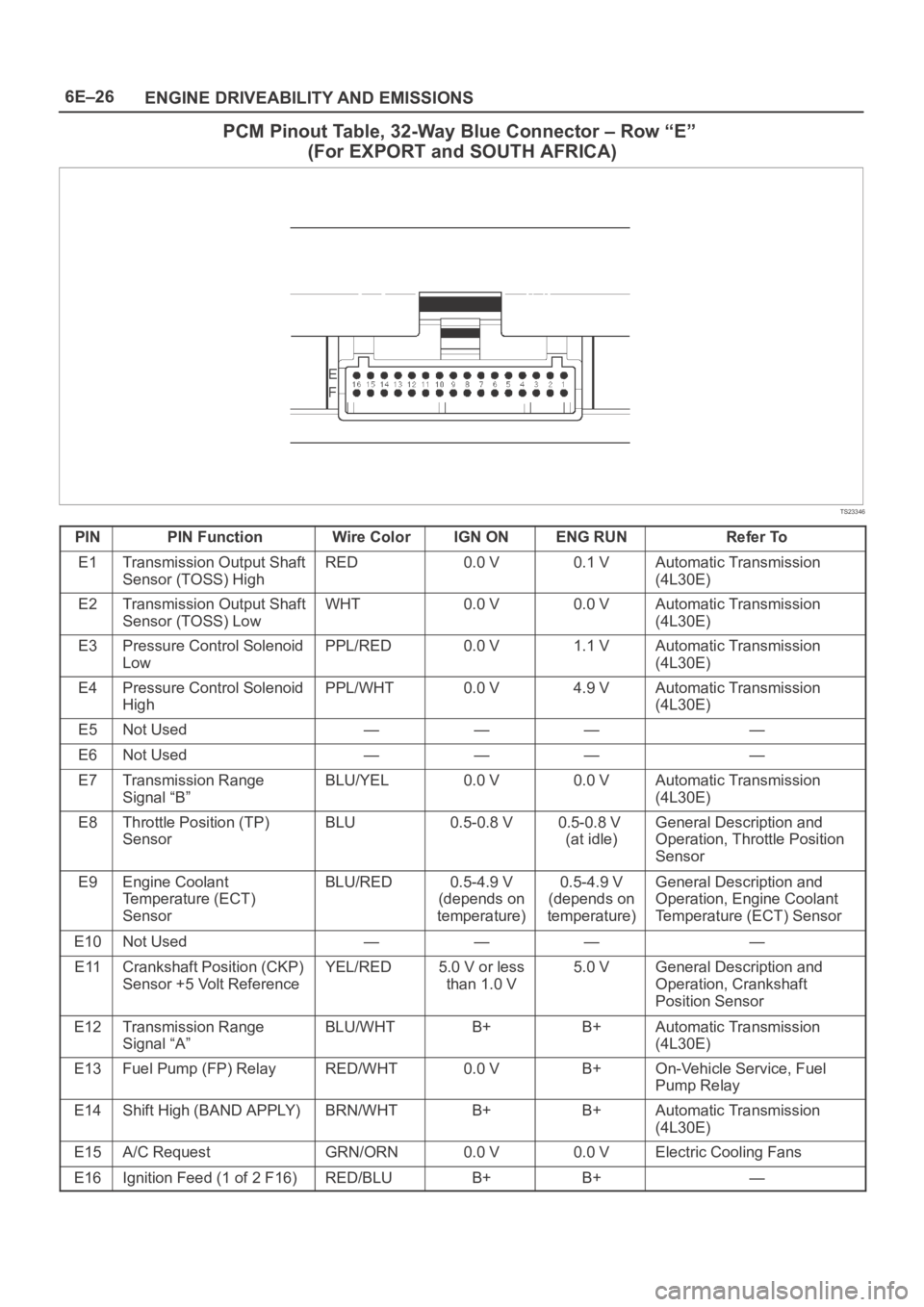
6E–26
ENGINE DRIVEABILITY AND EMISSIONS
PCM Pinout Table, 32-Way Blue Connector – Row “E”
(For EXPORT and SOUTH AFRICA)
TS23346
PINPIN FunctionWire ColorIGN ONENG RUNRefer To
E1Transmission Output Shaft
Sensor (TOSS) HighRED0.0 V0.1 VAutomatic Transmission
(4L30E)
E2Transmission Output Shaft
Sensor (TOSS) LowWHT0.0 V0.0 VAutomatic Transmission
(4L30E)
E3Pressure Control Solenoid
LowPPL/RED0.0 V1.1 VAutomatic Transmission
(4L30E)
E4Pressure Control Solenoid
HighPPL/WHT0.0 V4.9 VAutomatic Transmission
(4L30E)
E5Not Used————
E6Not Used————
E7Transmission Range
Signal “B”BLU/YEL0.0 V0.0 VAutomatic Transmission
(4L30E)
E8Throttle Position (TP)
SensorBLU0.5-0.8 V0.5-0.8 V
(at idle)General Description and
Operation, Throttle Position
Sensor
E9Engine Coolant
Temperature (ECT)
SensorBLU/RED0.5-4.9 V
(depends on
temperature)0.5-4.9 V
(depends on
temperature)General Description and
Operation, Engine Coolant
Temperature (ECT) Sensor
E10Not Used————
E11Crankshaft Position (CKP)
Sensor +5 Volt ReferenceYEL/RED5.0 V or less
than 1.0 V5.0 VGeneral Description and
Operation, Crankshaft
Position Sensor
E12Transmission Range
Signal “A”BLU/WHTB+B+Automatic Transmission
(4L30E)
E13Fuel Pump (FP) RelayRED/WHT0.0 VB+On-Vehicle Service, Fuel
Pump Relay
E14Shift High (BAND APPLY)BRN/WHTB+B+Automatic Transmission
(4L30E)
E15A/C RequestGRN/ORN0.0 V0.0 VElectric Cooling Fans
E16Ignition Feed (1 of 2 F16)RED/BLUB+B+—
Page 1144 of 6000
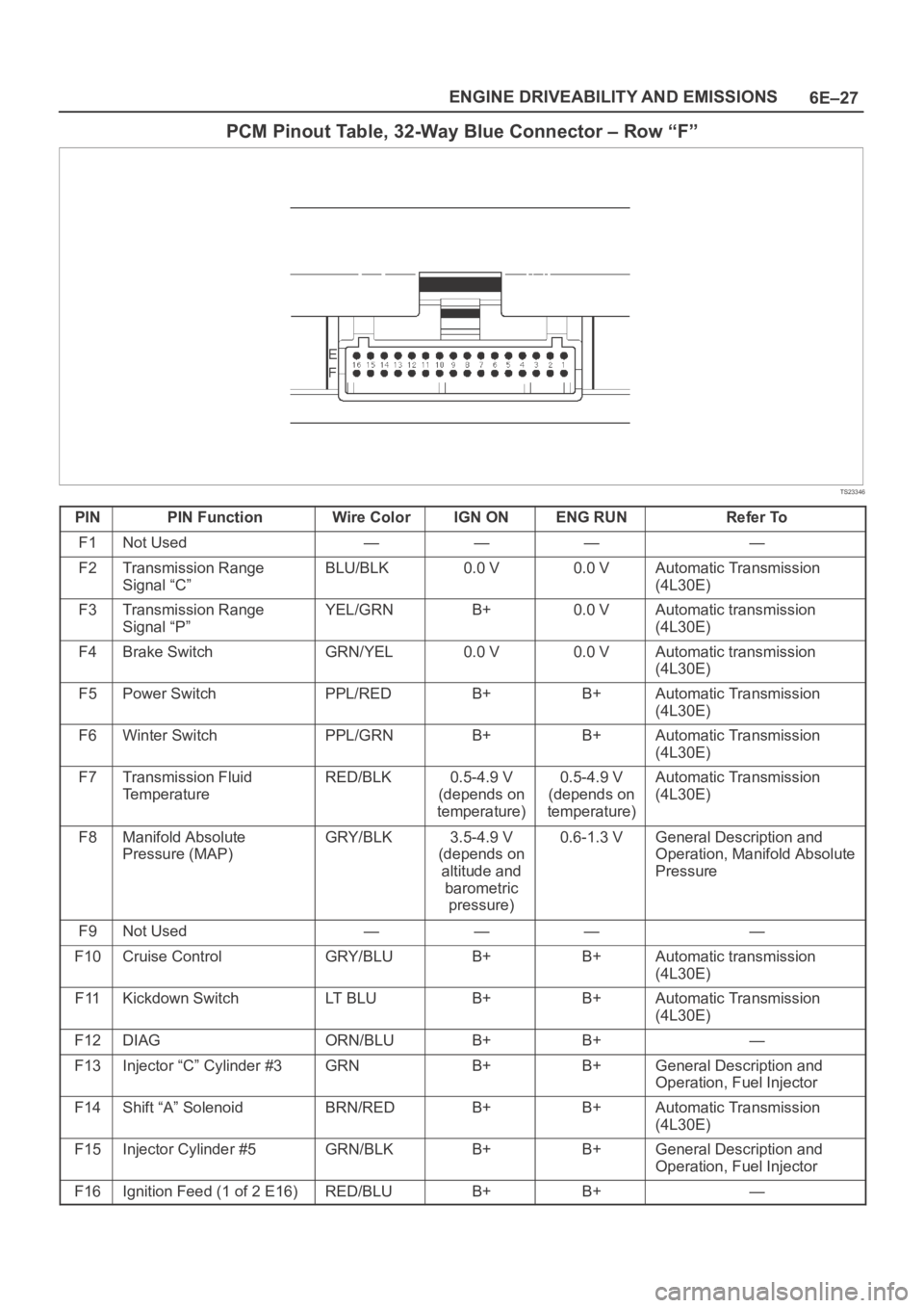
6E–27 ENGINE DRIVEABILITY AND EMISSIONS
PCM Pinout Table, 32-Way Blue Connector – Row “F”
TS23346
PINPIN FunctionWire ColorIGN ONENG RUNRefer To
F1Not Used————
F2Transmission Range
Signal “C”BLU/BLK0.0 V0.0 VAutomatic Transmission
(4L30E)
F3Transmission Range
Signal “P”YEL/GRNB+0.0 VAutomatic transmission
(4L30E)
F4Brake SwitchGRN/YEL0.0 V0.0 VAutomatic transmission
(4L30E)
F5Power SwitchPPL/REDB+B+Automatic Transmission
(4L30E)
F6Winter SwitchPPL/GRNB+B+Automatic Transmission
(4L30E)
F7Transmission Fluid
TemperatureRED/BLK0.5-4.9 V
(depends on
temperature)0.5-4.9 V
(depends on
temperature)Automatic Transmission
(4L30E)
F8Manifold Absolute
Pressure (MAP)GRY/BLK3.5-4.9 V
(depends on
altitude and
barometric
pressure)0.6-1.3 VGeneral Description and
Operation, Manifold Absolute
Pressure
F9Not Used————
F10Cruise ControlGRY/BLUB+B+Automatic transmission
(4L30E)
F11Kickdown SwitchLT B L UB+B+Automatic Transmission
(4L30E)
F12DIAGORN/BLUB+B+—
F13Injector “C” Cylinder #3GRNB+B+General Description and
Operation, Fuel Injector
F14Shift “A” SolenoidBRN/REDB+B+Automatic Transmission
(4L30E)
F15Injector Cylinder #5GRN/BLKB+B+General Description and
Operation, Fuel Injector
F16Ignition Feed (1 of 2 E16)RED/BLUB+B+—
Page 1146 of 6000
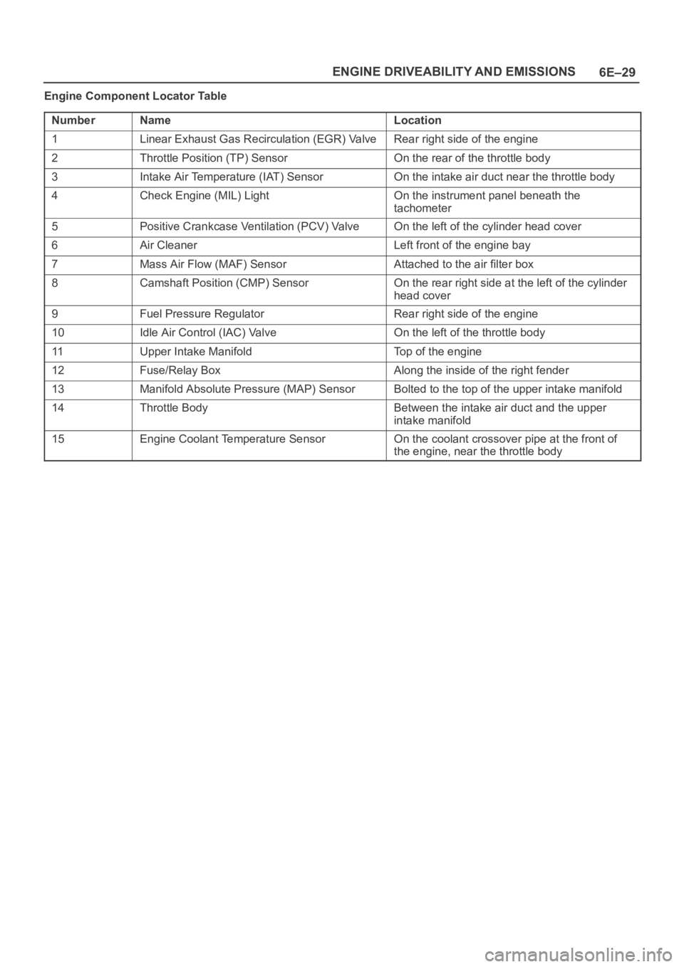
6E–29 ENGINE DRIVEABILITY AND EMISSIONS
Engine Component Locator Table
Number
NameLocation
1Linear Exhaust Gas Recirculation (EGR) ValveRear right side of the engine
2Throttle Position (TP) SensorOn the rear of the throttle body
3Intake Air Temperature (IAT) SensorOn the intake air duct near the throttle body
4Check Engine (MIL) LightOn the instrument panel beneath the
tachometer
5Positive Crankcase Ventilation (PCV) ValveOn the left of the cylinder head cover
6Air CleanerLeft front of the engine bay
7Mass Air Flow (MAF) SensorAttached to the air filter box
8Camshaft Position (CMP) SensorOn the rear right side at the left of the cylinder
head cover
9Fuel Pressure RegulatorRear right side of the engine
10Idle Air Control (IAC) ValveOn the left of the throttle body
11Upper Intake ManifoldTop of the engine
12Fuse/Relay BoxAlong the inside of the right fender
13Manifold Absolute Pressure (MAP) SensorBolted to the top of the upper intake manifold
14Throttle BodyBetween the intake air duct and the upper
intake manifold
15Engine Coolant Temperature SensorOn the coolant crossover pipe at the front of
the engine, near the throttle body