1998 OPEL FRONTERA charging
[x] Cancel search: chargingPage 2272 of 6000
TRANSMISSION CONTROL SYSTEM (4L30–E)7A1–27
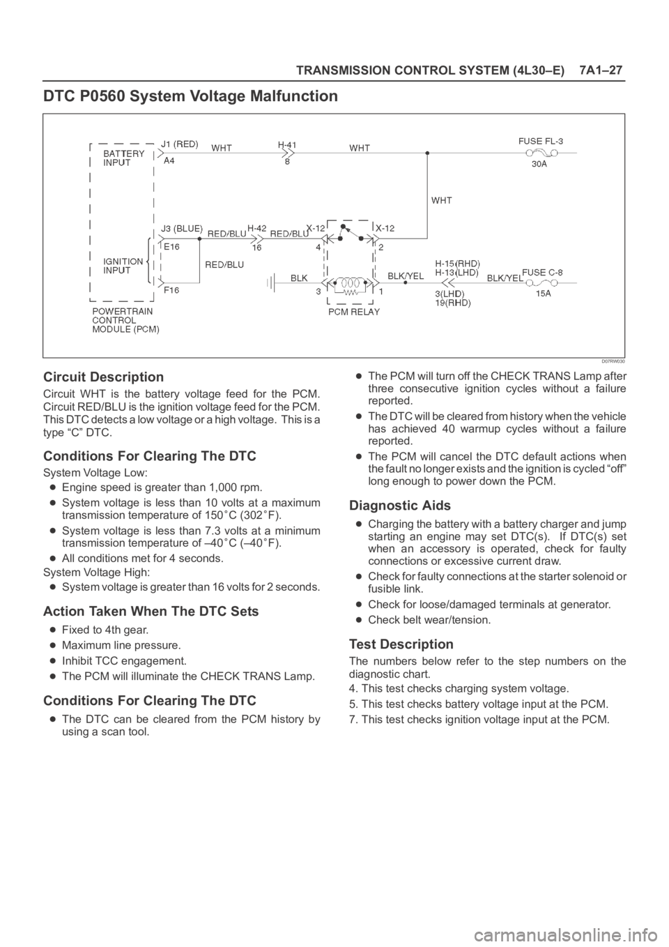
DTC P0560 System Voltage Malfunction
D07RW030
Circuit Description
Circuit WHT is the battery voltage feed for the PCM.
Circuit RED/BLU is the ignition voltage feed for the PCM.
This DTC detects a low voltage or a high voltage. This is a
type “C” DTC.
Conditions For Clearing The DTC
System Voltage Low:
Engine speed is greater than 1,000 rpm.
System voltage is less than 10 volts at a maximum
transmission temperature of 150
C (302F).
System voltage is less than 7.3 volts at a minimum
transmission temperature of –40
C (–40F).
All conditions met for 4 seconds.
System Voltage High:
System voltage is greater than 16 volts for 2 seconds.
Action Taken When The DTC Sets
Fixed to 4th gear.
Maximum line pressure.
Inhibit TCC engagement.
The PCM will illuminate the CHECK TRANS Lamp.
Conditions For Clearing The DTC
The DTC can be cleared from the PCM history by
using a scan tool.
The PCM will turn off the CHECK TRANS Lamp after
three consecutive ignition cycles without a failure
reported.
The DTC will be cleared from history when the vehicle
has achieved 40 warmup cycles without a failure
reported.
The PCM will cancel the DTC default actions when
the fault no longer exists and the ignition is cycled “off”
long enough to power down the PCM.
Diagnostic Aids
Charging the battery with a battery charger and jump
starting an engine may set DTC(s). If DTC(s) set
when an accessory is operated, check for faulty
connections or excessive current draw.
Check for faulty connections at the starter solenoid or
fusible link.
Check for loose/damaged terminals at generator.
Check belt wear/tension.
Test Description
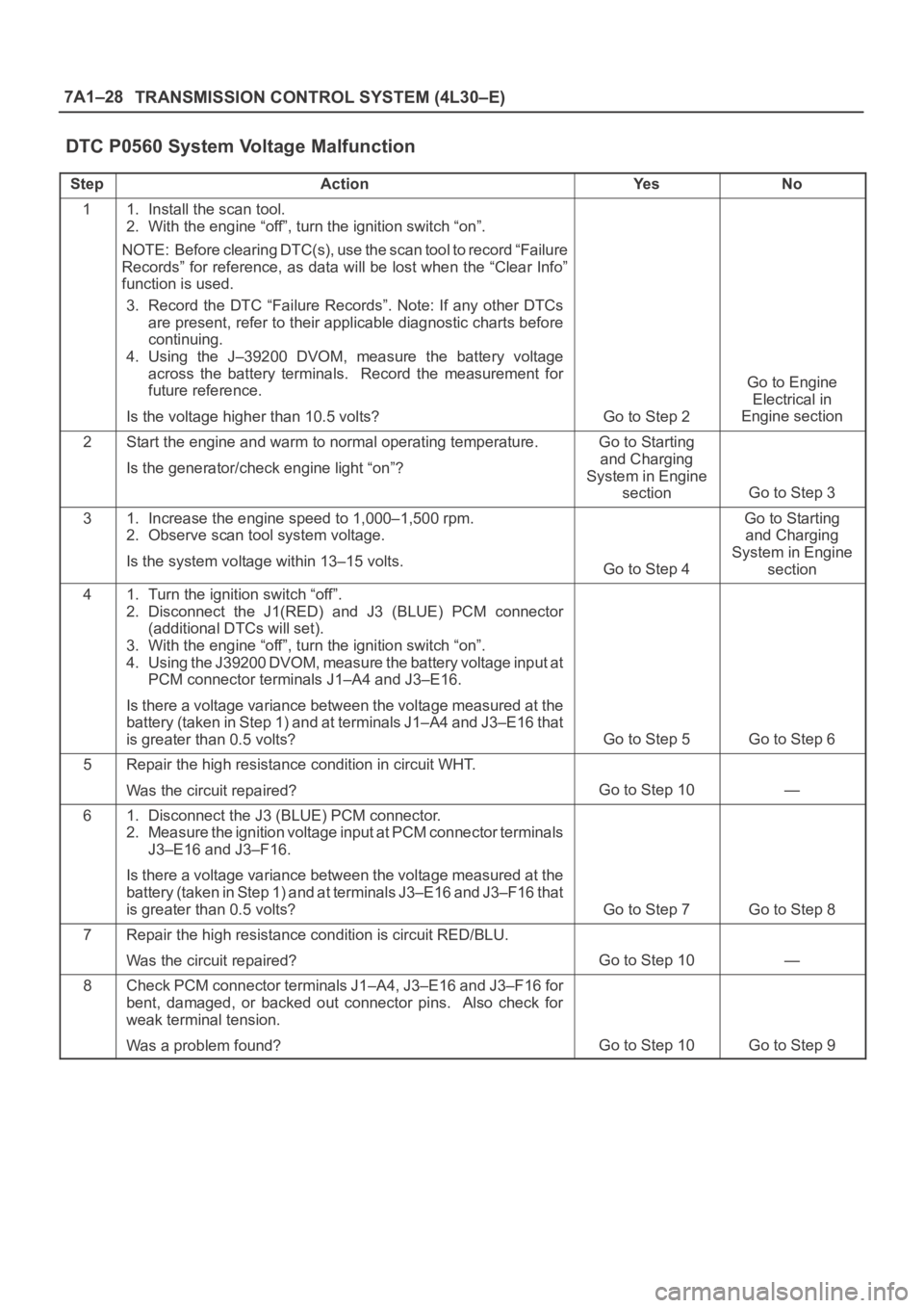
The numbers below refer to the step numbers on the
diagnostic chart.
4. This test checks charging system voltage.
5. This test checks battery voltage input at the PCM.
7. This test checks ignition voltage input at the PCM.
Page 2273 of 6000
7A1–28
TRANSMISSION CONTROL SYSTEM (4L30–E)
DTC P0560 System Voltage Malfunction
StepActionYe sNo
11. Install the scan tool.
2. With the engine “off”, turn the ignition switch “on”.
NOTE: Before clearing DTC(s), use the scan tool to record “Failure
Records” for reference, as data will be lost when the “Clear Info”
function is used.
3. Record the DTC “Failure Records”. Note: If any other DTCs
are present, refer to their applicable diagnostic charts before
continuing.
4. Using the J–39200 DVOM, measure the battery voltage
across the battery terminals. Record the measurement for
future reference.
Is the voltage higher than 10.5 volts?
Go to Step 2
Go to Engine
Electrical in
Engine section
2Start the engine and warm to normal operating temperature.
Is the generator/check engine light “on”?Go to Starting
and Charging
System in Engine
section
Go to Step 3
31. Increase the engine speed to 1,000–1,500 rpm.
2. Observe scan tool system voltage.
Is the system voltage within 13–15 volts.
Go to Step 4
Go to Starting
and Charging
System in Engine
section
41. Turn the ignition switch “off”.
2. Disconnect the J1(RED) and J3 (BLUE) PCM connector
(additional DTCs will set).
3. With the engine “off”, turn the ignition switch “on”.
4. Using the J39200 DVOM, measure the battery voltage input at
PCM connector terminals J1–A4 and J3–E16.
Is there a voltage variance between the voltage measured at the
battery (taken in Step 1) and at terminals J1–A4 and J3–E16 that
is greater than 0.5 volts?
Go to Step 5Go to Step 6
5Repair the high resistance condition in circuit WHT.
Was the circuit repaired?
Go to Step 10—
61. Disconnect the J3 (BLUE) PCM connector.
2. Measure the ignition voltage input at PCM connector terminals
J3–E16 and J3–F16.
Is there a voltage variance between the voltage measured at the
battery (taken in Step 1) and at terminals J3–E16 and J3–F16 that
is greater than 0.5 volts?
Go to Step 7Go to Step 8
7Repair the high resistance condition is circuit RED/BLU.
Was the circuit repaired?
Go to Step 10—
8Check PCM connector terminals J1–A4, J3–E16 and J3–F16 for
bent, damaged, or backed out connector pins. Also check for
weak terminal tension.
Was a problem found?
Go to Step 10Go to Step 9
Page 3566 of 6000
PAGE BACK PAGE NEXT
THIS MALUAL INCLUDES THE FOLLOWING SECTIONS:
6VD1/6VE1
SECTION No. CONTRNTS
6A ENGINE MECHANICAL
6B ENGINE COOLING
6C ENGINE FUEL
6D1 ENGINE ELECTRICAL
6D2 IGNITION SYSTEM
6D3 STARTING AND CHARGING SYSTEM
6E ENGINE DRIVEABILITY AND EMISSIONS
6F ENGINE EXHAUST
6G ENGINE LUBRICATION
6H ENGINE SPEED CONTROL SYSTEM
6J INDUCTION
HOME
6A
6B
6C
6D1
6D2
6D3
6E
6F
6G
6H
6J
Page 3782 of 6000
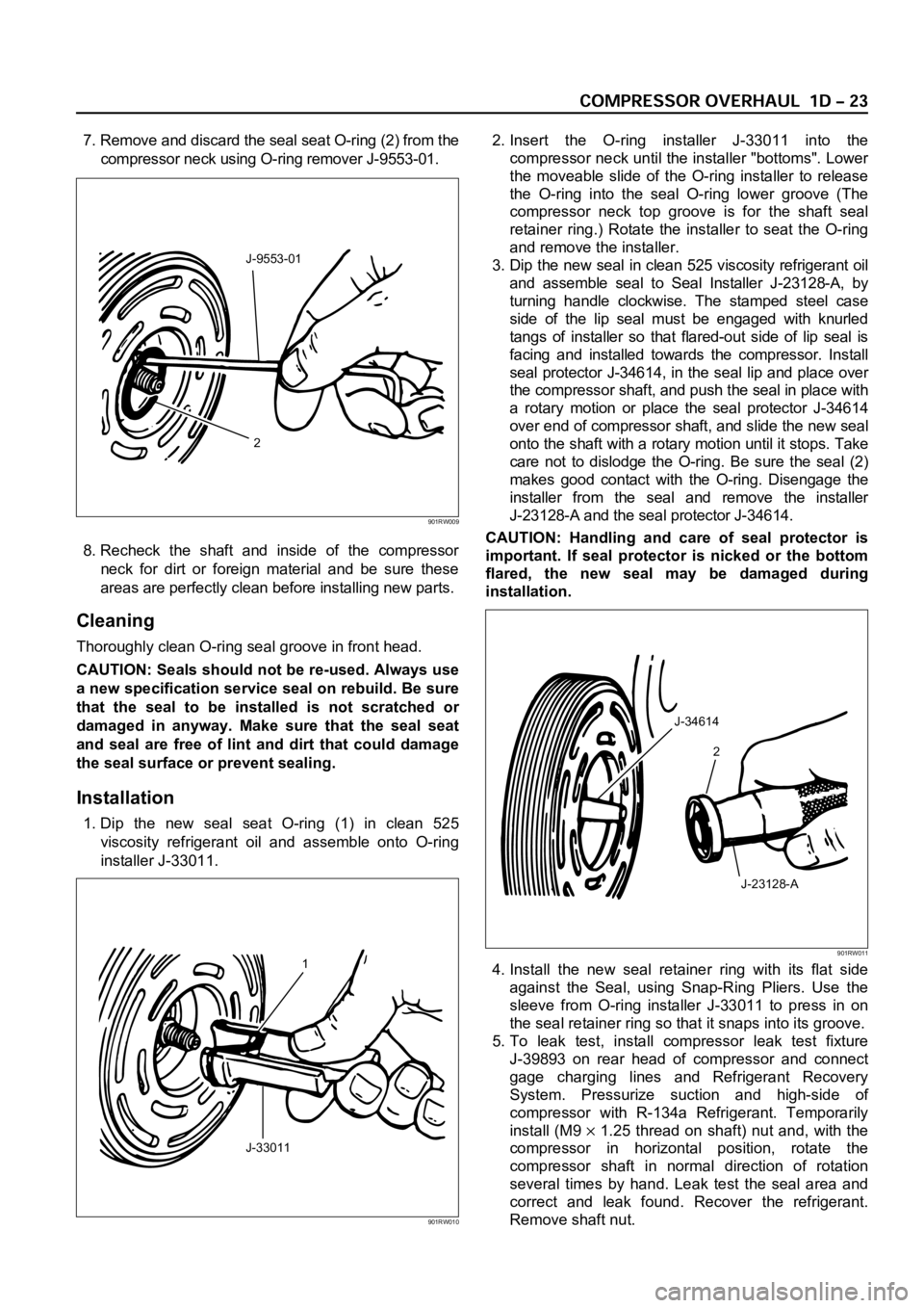
7. Remove and discard the seal seat O-ring (2) from the
compressor neck using O-ring remover J-9553-01.
8. Recheck the shaft and inside of the compressor
neck for dirt or foreign material and be sure these
areas are perfectly clean before installing new parts.
Cleaning
Thoroughly clean O-ring seal groove in front head.
CAUTION: Seals should not be re-used. Always use
a new specification service seal on rebuild. Be sure
that the seal to be installed is not scratched or
damaged in anyway. Make sure that the seal seat
and seal are free of lint and dirt that could damage
the seal surface or prevent sealing.
Installation
1. Dip the new seal seat O-ring (1) in clean 525
viscosity refrigerant oil and assemble onto O-ring
installer J-33011.2. Insert the O-ring installer J-33011 into the
compressor neck until the installer "bottoms". Lower
the moveable slide of the O-ring installer to release
the O-ring into the seal O-ring lower groove (The
compressor neck top groove is for the shaft seal
retainer ring.) Rotate the installer to seat the O-ring
and remove the installer.
3. Dip the new seal in clean 525 viscosity refrigerant oil
and assemble seal to Seal Installer J-23128-A, by
turning handle clockwise. The stamped steel case
side of the lip seal must be engaged with knurled
tangs of installer so that flared-out side of lip seal is
facing and installed towards the compressor. Install
seal protector J-34614, in the seal lip and place over
the compressor shaft, and push the seal in place with
a rotary motion or place the seal protector J-34614
over end of compressor shaft, and slide the new seal
onto the shaft with a rotary motion until it stops. Take
care not to dislodge the O-ring. Be sure the seal (2)
makes good contact with the O-ring. Disengage the
installer from the seal and remove the installer
J-23128-A and the seal protector J-34614.
CAUTION: Handling and care of seal protector is
important. If seal protector is nicked or the bottom
flared, the new seal may be damaged during
installation.
4. Install the new seal retainer ring with its flat side
against the Seal, using Snap-Ring Pliers. Use the
sleeve from O-ring installer J-33011 to press in on
the seal retainer ring so that it snaps into its groove.
5. To leak test, install compressor leak test fixture
J-39893 on rear head of compressor and connect
gage charging lines and Refrigerant Recovery
System. Pressurize suction and high-side of
compressor with R-134a Refrigerant. Temporarily
install (M9
1.25 thread on shaft) nut and, with the
compressor in horizontal position, rotate the
compressor shaft in normal direction of rotation
several times by hand. Leak test the seal area and
correct and leak found. Recover the refrigerant.
Remove shaft nut.
2 J-9553-01
901RW009
1
J-33011
901RW010
J-34614
2
J-23128-A
901RW011
Page 3783 of 6000

6. Remove any excess oil resulting from installing the
new seal parts from the shaft and inside the
compressor neck.
7. Install the clutch plate and hub assembly as
described previously.8. Reinstall compressor belt and tighten bracket.
9. Evacuate and charge the refrigerant system.
COMPRESSOR PRESSURE RELIEF VALVE
Removal
1. Recover the refrigerant using Refrigerant Recovery
System.
2. Remove old pressure relief valve.
Installation
1. Clean valve seat area on rear head.2. Lubricate O-ring of new pressure relief valve and
O-ring assembly with new 525 viscosity refrigerant
oil. Install new valve and torque in place, 9.0 Nꞏm
(6.1 ft lbs)
3. Evacuate and recharge the system.
4. Leak test system.
COMPRESSOR OIL
Compressor Oil Check
The oil used to lubricate the compressor is circulating
with the refrigerant.
Whenever replacing any component of the system or a
large amount of gas leakage occurs, add oil to maintain
the original amount of oil.
Checking and Adjusting Oil Quantity for
Used Compressor
1. Perform oil return operation. Refer to Oil Return
Operation in this section.
2. Discharge and recover refrigerant and remove the
compressor.
3. Drain the compressor oil and measure the extracted
oil with a measuring cylinder.
4. If the amount of oil drained is much less than 90 cc
(3.0 fl. oz.), some refrigerant may have leaked out.
Conduct a leak tests on the connections of each
system, and if necessary, repair or replace faulty
parts.
5. Check the compressor oil contamination. (Refer to
Contamination of Compressor Oil in this section.)
6. Adjust the oil level following the next procedure
below.7. Install the compressor, then evacuate, charge and
perform the oil return operation.
8. Check system operation.
When it is impossible to preform oil return
operation, the compressor oil should be checked in
the following order:
1. Discharge and recover refrigerant and remove the
compressor.
2. Drain the compressor oil and measure the extracted
oil with a measuring cylinder.
3. Check the oil for contamination.
4. If more than 90 cc (3.0 fl. oz.) of oil is extracted from
the compressor, supply the same amount of oil to
the compressor to be installed. If the amount of oil
extracted is less than 90 cc (3.0 fl. oz.), recheck the
compressor oil in the following order:
5. Supply 90 cc (3.0 fl. oz.) of oil to the compressor
and install it onto the vehicle.
6. Evacuate and recharge with the proper amount of
refrigerant.
7. Perform the oil return operation.
8. Remove the compressor and recheck the amount of
oil.
9. Adjust the compressor oil, if necessary.
Checking and Adjusting for Compressor
Replacement
The oil is not charged in compressor (service parts). So
it is necessary to charge the proper amount of oil to the
new compressor. (Oil Capacity)
Capacity total in system 150 cc (5.0 fl.oz)
Compressor (Service 150 cc (5.0 fl.oz)
parts) charging amount
(Collected Amount) (Charging Amount)
more than 90 cc same as collected
(3.0 fl.oz) amount
less than 90 cc (3.0 fl.oz) 90 cc (3.0 fl.oz)
(Collected Amount) (Charging Amount)
more than 90 cc same as collected
(3.0 fl.oz) amount
less than 90 cc (3.0 fl.oz) 90 cc (3.0 fl.oz)
Page 3784 of 6000

1. Perform oil return operation.
2. Discharge and recover the refrigerant and remove
the compressor.
3. Drain the compressor oil and measure the extracted
oil.
4. Check the compressor oil for contamination.
5. Adjust the oil level as required.
6. Evacuate, charge and perform the oil return
operation.
7. Check the system operation.
Contamination of Compressor Oil
Unlike engine oil, no cleaning agent is added to the
compressor oil. Even if the compressor runs for a long
period of time (approximately one season), the oil never
becomes contaminated as long as there is nothing
wrong with the compressor or its method of use.
Inspect the extracted oil for any of the following
conditions:
The capacity of the oil has increased.
The oil has changed to red.
Foreign substances, metal powder, etc., are present
in the oil.
If any of these conditions exists, the compressor
oil is contaminated. Whenever contaminated
compressor oil is discovered, the receiver/drier
must be replaced.
Oil Return Operation
There is close affinity between the oil and the
refrigerant. During normal operation, part of the oil
recirculates with the refrigerant in the system. When
checking the amount of oil in the system, or replacing
any component of the system, the compressor must be
run in advance for oil return operation. The procedure
is as follows:
1. Open all the doors and the engine hood.
2. Start the engine and air conditioning switch to "ON"
and set the fan control knob at its highest position.
3. Run the compressor for more than 20 minutes
between 800 and 1,000 rpm in order to operate the
system.
4. Stop the engine.
Replacement of Component Parts
When replacing the system component parts, supply
the following amount of oil to the component parts to be
installed.
Compressor Leak Testing (External and
Internal)
Bench-Check Procedure
1. Install test plate J-39893 on rear head of compressor.
2. Using Refrigerant Recovery System, attach center
hose of manifold gage set on charging station to a
refrigerant drum standing in an upright drum.
3. Connect charging station high and low pressure
lines to corresponding fittings on test plate J-39893.
Suction port (low-side) of compressor has large
internal opening. Discharge port (high-side) has
smaller internal opening into compressor and
deeper recess.
4. Open low pressure control, high pressure control
and refrigerant control on charging station to allow
refrigerant vapor to flow into compressor.
5. Using a leak detector, check for leaks at pressure
relief valve, rear head switch location, compressor
front and rear head seals, center cylinder seal,
through bolt head gaskets and compressor shaft
seal. After checking, shut off low pressure control
and high-pressure control on charging station.
6. If an external leak is present, perform the necessary
corrective measures and recheck for leaks to make
certain the leak has been connected.
7. Recover the refrigerant.
8. Disconnect both hoses from the test plate J-39893.
9. Add 90 ml (3 oz.) new PAG lubricant to the
compressor assembly. Rotate the complete
compressor assembly (not the crankshaft or drive
plate hub) slowly several turns to distribute oil to all
cylinder and piston areas.
10. Install a M9
1.25 threaded nut on the compressor
crankshaft if the drive plate and clutch assembly are
not installed.
11. Using a box-end wrench or socket and handle,
rotate the compressor crankshaft or clutch drive
plate on the crankshaft several turns to insure
piston assembly to cylinder wall lubrication.
12. Using Refrigerant Recovery System, connect the
charging station high-pressure line to the test plate
J-39893 high-side connector.
13. Using Refrigerant Recovery System, connect the
charging station low-pressure line to the low
pressure port of the test plate J-39893. Oil will drain
out of the compressor suction port if the compressor
is positioned with the suction port downward. (Component parts to be (Amount of Oil)
installed)
Evaporator 50 cc (1.7 fl. oz.)
Condenser 30 cc (1.0 fl. oz.)
Receiver/dryer 30 cc (1.0 fl. oz.)
Refrigerant line (one 10 cc (0.3 fl. oz.)
piece)
(Amount of oil drained (Charging amount of oil
from used compressor) to new compressor)
more than 90 cc same as drained amount
(3.0 fl.oz)
less than 90 cc (3.0 fl.oz) 90 cc (3.0 fl.oz)
Page 4204 of 6000
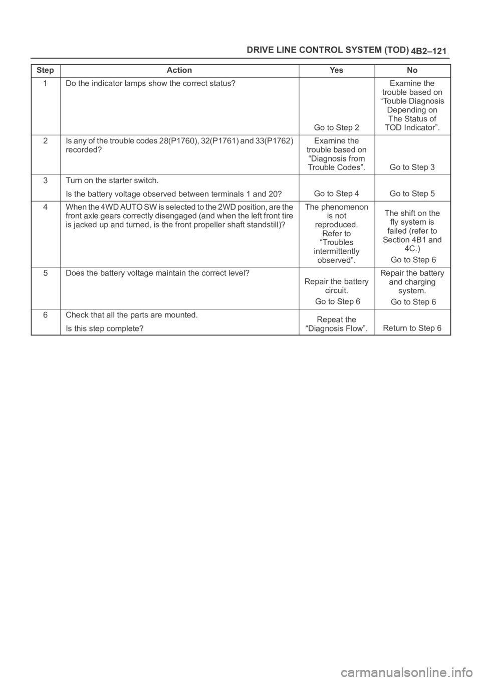
4B2–121 DRIVE LINE CONTROL SYSTEM (TOD)
StepActionYe sNo
1Do the indicator lamps show the correct status?
Go to Step 2
Examine the
trouble based on
“Touble Diagnosis
Depending on
The Status of
TOD Indicator”.
2Is any of the trouble codes 28(P1760), 32(P1761) and 33(P1762)
recorded?Examine the
trouble based on
“Diagnosis from
Trouble Codes”.
Go to Step 3
3Turn on the starter switch.
Is the battery voltage observed between terminals 1 and 20?
Go to Step 4Go to Step 5
4W h e n t h e 4 W D A U T O S W i s s e l e c t e d t o t h e 2 W D p o s i t i o n , a r e t h e
front axle gears correctly disengaged (and when the left front tire
is jacked up and turned, is the front propeller shaft standstill)?The phenomenon
is not
reproduced.
Refer to
“Troubles
intermittently
observed”.The shift on the
fly system is
failed (refer to
Section 4B1 and
4C.)
Go to Step 6
5Does the battery voltage maintain the correct level?
Repair the battery
circuit.
Go to Step 6
Repair the battery
and charging
system.
Go to Step 6
6Check that all the parts are mounted.
Is this step complete?Repeat the
“Diagnosis Flow”.
Return to Step 6
Page 4497 of 6000
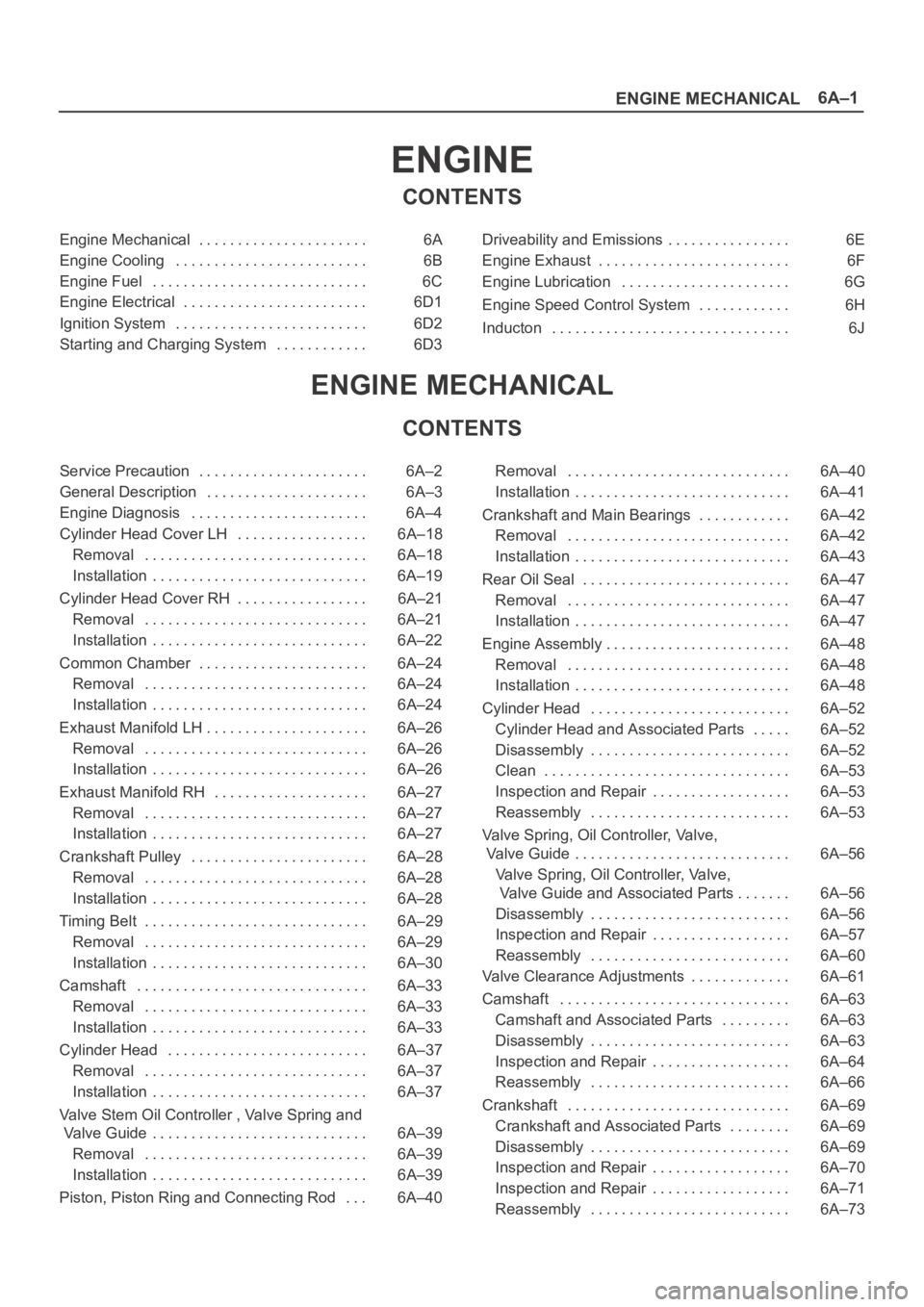
6A–1
ENGINE MECHANICAL
ENGINE
CONTENTS
Engine Mechanical 6A. . . . . . . . . . . . . . . . . . . . . .
Engine Cooling 6B. . . . . . . . . . . . . . . . . . . . . . . . .
Engine Fuel 6C. . . . . . . . . . . . . . . . . . . . . . . . . . . .
Engine Electrical 6D1. . . . . . . . . . . . . . . . . . . . . . . .
Ignition System 6D2. . . . . . . . . . . . . . . . . . . . . . . . .
Starting and Charging System 6D3. . . . . . . . . . . . Driveability and Emissions 6E. . . . . . . . . . . . . . . .
Engine Exhaust 6F. . . . . . . . . . . . . . . . . . . . . . . . .
Engine Lubrication 6G. . . . . . . . . . . . . . . . . . . . . .
Engine Speed Control System 6H. . . . . . . . . . . .
Inducton 6J. . . . . . . . . . . . . . . . . . . . . . . . . . . . . . .
ENGINE MECHANICAL
CONTENTS
Service Precaution 6A–2. . . . . . . . . . . . . . . . . . . . . .
General Description 6A–3. . . . . . . . . . . . . . . . . . . . .
Engine Diagnosis 6A–4. . . . . . . . . . . . . . . . . . . . . . .
Cylinder Head Cover LH 6A–18. . . . . . . . . . . . . . . . .
Removal 6A–18. . . . . . . . . . . . . . . . . . . . . . . . . . . . .
Installation 6A–19. . . . . . . . . . . . . . . . . . . . . . . . . . . .
Cylinder Head Cover RH 6A–21. . . . . . . . . . . . . . . . .
Removal 6A–21. . . . . . . . . . . . . . . . . . . . . . . . . . . . .
Installation 6A–22. . . . . . . . . . . . . . . . . . . . . . . . . . . .
Common Chamber 6A–24. . . . . . . . . . . . . . . . . . . . . .
Removal 6A–24. . . . . . . . . . . . . . . . . . . . . . . . . . . . .
Installation 6A–24. . . . . . . . . . . . . . . . . . . . . . . . . . . .
Exhaust Manifold LH 6A–26. . . . . . . . . . . . . . . . . . . . .
Removal 6A–26. . . . . . . . . . . . . . . . . . . . . . . . . . . . .
Installation 6A–26. . . . . . . . . . . . . . . . . . . . . . . . . . . .
Exhaust Manifold RH 6A–27. . . . . . . . . . . . . . . . . . . .
Removal 6A–27. . . . . . . . . . . . . . . . . . . . . . . . . . . . .
Installation 6A–27. . . . . . . . . . . . . . . . . . . . . . . . . . . .
Crankshaft Pulley 6A–28. . . . . . . . . . . . . . . . . . . . . . .
Removal 6A–28. . . . . . . . . . . . . . . . . . . . . . . . . . . . .
Installation 6A–28. . . . . . . . . . . . . . . . . . . . . . . . . . . .
Timing Belt 6A–29. . . . . . . . . . . . . . . . . . . . . . . . . . . . .
Removal 6A–29. . . . . . . . . . . . . . . . . . . . . . . . . . . . .
Installation 6A–30. . . . . . . . . . . . . . . . . . . . . . . . . . . .
Camshaft 6A–33. . . . . . . . . . . . . . . . . . . . . . . . . . . . . .
Removal 6A–33. . . . . . . . . . . . . . . . . . . . . . . . . . . . .
Installation 6A–33. . . . . . . . . . . . . . . . . . . . . . . . . . . .
Cylinder Head 6A–37. . . . . . . . . . . . . . . . . . . . . . . . . .
Removal 6A–37. . . . . . . . . . . . . . . . . . . . . . . . . . . . .
Installation 6A–37. . . . . . . . . . . . . . . . . . . . . . . . . . . .
Valve Stem Oil Controller , Valve Spring and
Valve Guide 6A–39. . . . . . . . . . . . . . . . . . . . . . . . . . . .
Removal 6A–39. . . . . . . . . . . . . . . . . . . . . . . . . . . . .
Installation 6A–39. . . . . . . . . . . . . . . . . . . . . . . . . . . .
Piston, Piston Ring and Connecting Rod 6A–40. . . Removal 6A–40. . . . . . . . . . . . . . . . . . . . . . . . . . . . .
Installation 6A–41. . . . . . . . . . . . . . . . . . . . . . . . . . . .
Crankshaft and Main Bearings 6A–42. . . . . . . . . . . .
Removal 6A–42. . . . . . . . . . . . . . . . . . . . . . . . . . . . .
Installation 6A–43. . . . . . . . . . . . . . . . . . . . . . . . . . . .
Rear Oil Seal 6A–47. . . . . . . . . . . . . . . . . . . . . . . . . . .
Removal 6A–47. . . . . . . . . . . . . . . . . . . . . . . . . . . . .
Installation 6A–47. . . . . . . . . . . . . . . . . . . . . . . . . . . .
Engine Assembly 6A–48. . . . . . . . . . . . . . . . . . . . . . . .
Removal 6A–48. . . . . . . . . . . . . . . . . . . . . . . . . . . . .
Installation 6A–48. . . . . . . . . . . . . . . . . . . . . . . . . . . .
Cylinder Head 6A–52. . . . . . . . . . . . . . . . . . . . . . . . . .
Cylinder Head and Associated Parts 6A–52. . . . .
Disassembly 6A–52. . . . . . . . . . . . . . . . . . . . . . . . . .
Clean 6A–53. . . . . . . . . . . . . . . . . . . . . . . . . . . . . . . .
Inspection and Repair 6A–53
. . . . . . . . . . . . . . . . . .
Reassembly 6A–53. . . . . . . . . . . . . . . . . . . . . . . . . .
Valve Spring, Oil Controller, Valve,
Valve Guide 6A–56. . . . . . . . . . . . . . . . . . . . . . . . . . . .
Valve Spring, Oil Controller, Valve,
Valve Guide and Associated Parts 6A–56. . . . . . .
Disassembly 6A–56. . . . . . . . . . . . . . . . . . . . . . . . . .
Inspection and Repair 6A–57. . . . . . . . . . . . . . . . . .
Reassembly 6A–60. . . . . . . . . . . . . . . . . . . . . . . . . .
Valve Clearance Adjustments 6A–61. . . . . . . . . . . . .
Camshaft 6A–63. . . . . . . . . . . . . . . . . . . . . . . . . . . . . .
Camshaft and Associated Parts 6A–63. . . . . . . . .
Disassembly 6A–63. . . . . . . . . . . . . . . . . . . . . . . . . .
Inspection and Repair 6A–64. . . . . . . . . . . . . . . . . .
Reassembly 6A–66. . . . . . . . . . . . . . . . . . . . . . . . . .
Crankshaft 6A–69. . . . . . . . . . . . . . . . . . . . . . . . . . . . .
Crankshaft and Associated Parts 6A–69. . . . . . . .
Disassembly 6A–69. . . . . . . . . . . . . . . . . . . . . . . . . .
Inspection and Repair 6A–70. . . . . . . . . . . . . . . . . .
Inspection and Repair 6A–71. . . . . . . . . . . . . . . . . .
Reassembly 6A–73. . . . . . . . . . . . . . . . . . . . . . . . . .