1998 OPEL FRONTERA brake sensor
[x] Cancel search: brake sensorPage 1898 of 6000
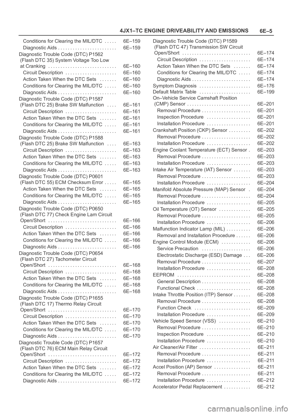
6E–5 4JX1–TC ENGINE DRIVEABILITY AND EMISSIONS
Conditions for Clearing the MIL/DTC 6E–159. . . . .
Diagnostic Aids 6E–159. . . . . . . . . . . . . . . . . . . . . . . .
Diagnostic Trouble Code (DTC) P1562
(Flash DTC 35) System Voltage Too Low
at Cranking 6E–160. . . . . . . . . . . . . . . . . . . . . . . . . . . .
Circuit Description 6E–160. . . . . . . . . . . . . . . . . . . . .
Action Taken When the DTC Sets 6E–160. . . . . . .
Conditions for Clearing the MIL/DTC 6E–160. . . . .
Diagnostic Aids 6E–160. . . . . . . . . . . . . . . . . . . . . . . .
Diagnostic Trouble Code (DTC) P1587
(Flash DTC 25) Brake SW Malfunction 6E–161. . . .
Circuit Description 6E–161. . . . . . . . . . . . . . . . . . . . .
Action Taken When the DTC Sets 6E–161. . . . . . .
Conditions for Clearing the MIL/DTC 6E–161. . . . .
Diagnostic Aids 6E–161. . . . . . . . . . . . . . . . . . . . . . . .
Diagnostic Trouble Code (DTC) P1588
(Flash DTC 25) Brake SW Malfunction 6E–163. . . .
Circuit Description 6E–163. . . . . . . . . . . . . . . . . . . . .
Action Taken When the DTC Sets 6E–163. . . . . . .
Conditions for Clearing the MIL/DTC 6E–163. . . . .
Diagnostic Aids 6E–163. . . . . . . . . . . . . . . . . . . . . . . .
Diagnostic Trouble Code (DTC) P0601
(Flash DTC 55) ECM Checksum Error 6E–165. . . . .
Action Taken When the DTC Sets 6E–165. . . . . . .
Conditions for Clearing the MIL/DTC 6E–165. . . . .
Diagnostic Aids 6E–165. . . . . . . . . . . . . . . . . . . . . . . .
Diagnostic Trouble Code (DTC) P0650
(Flash DTC 77) Check Engine Lam Circuit
Open/Short 6E–166. . . . . . . . . . . . . . . . . . . . . . . . . . . .
Circuit Description 6E–166. . . . . . . . . . . . . . . . . . . . .
Action Taken When the DTC Sets 6E–166. . . . . . .
Conditions for Clearing the MIL/DTC 6E–166. . . . .
Diagnostic Aids 6E–166. . . . . . . . . . . . . . . . . . . . . . . .
Diagnostic Trouble Code (DTC) P0654
(Flash DTC 27) Tachometer Circuit
Open/Short 6E–168. . . . . . . . . . . . . . . . . . . . . . . . . . . .
Circuit Description 6E–168. . . . . . . . . . . . . . . . . . . . .
Action Taken When the DTC Sets 6E–168. . . . . . .
Conditions for Clearing the MIL/DTC 6E–168. . . . .
Diagnostic Aids 6E–168. . . . . . . . . . . . . . . . . . . . . . . .
Diagnostic Trouble Code (DTC) P1655
(Flash DTC 17) Thermo Relay Circuit
Open/Short 6E–170. . . . . . . . . . . . . . . . . . . . . . . . . . . .
Circuit Description 6E–170. . . . . . . . . . . . . . . . . . . . .
Action Taken When the DTC Sets 6E–170. . . . . . .
Conditions for Clearing the MIL/DTC 6E–170. . . . .
Diagnostic Aids 6E–170. . . . . . . . . . . . . . . . . . . . . . . .
Diagnostic Trouble Code (DTC) P1657
(Flash DTC 76) ECM Main Relay Circuit
Open/Short 6E–172. . . . . . . . . . . . . . . . . . . . . . . . . . . .
Circuit Description 6E–172. . . . . . . . . . . . . . . . . . . . .
Action Taken When the DTC Sets 6E–172. . . . . . .
Conditions for Clearing the MIL/DTC 6E–172. . . . .
Diagnostic Aids 6E–172. . . . . . . . . . . . . . . . . . . . . . . . Diagnostic Trouble Code (DTC) P1589
(Flash DTC 47) Transmission SW Circuit
Open/Short 6E–174. . . . . . . . . . . . . . . . . . . . . . . . . . . .
Circuit Description 6E–174. . . . . . . . . . . . . . . . . . . . .
Action Taken When the DTC Sets 6E–174. . . . . . .
Conditions for Clearing the MIL/DTC 6E–174. . . . .
Diagnostic Aids 6E–174. . . . . . . . . . . . . . . . . . . . . . . .
Symptom Diagnosis 6E–176. . . . . . . . . . . . . . . . . . . . .
Default Matrix Table 6E–199. . . . . . . . . . . . . . . . . . . . .
On–Vehicle Service Camshaft Position
(CMP) Sensor 6E–201. . . . . . . . . . . . . . . . . . . . . . . . . .
Removal Procedure 6E–201. . . . . . . . . . . . . . . . . . . .
Inspection Procedure 6E–201. . . . . . . . . . . . . . . . . .
Installation Procedure 6E–201. . . . . . . . . . . . . . . . . .
Crankshaft Position (CKP) Sensor 6E–202. . . . . . . . .
Removal Procedure 6E–202. . . . . . . . . . . . . . . . . . . .
Installation Procedure 6E–202. . . . . . . . . . . . . . . . . .
Engine Coolant Temperature (ECT) Sensor 6E–203.
Removal Procedure 6E–203. . . . . . . . . . . . . . . . . . . .
Installation Procedure 6E–203. . . . . . . . . . . . . . . . . .
Intake Air Temperature (IAT) Sensor 6E–203. . . . . . .
Removal Procedure 6E–203. . . . . . . . . . . . . . . . . . . .
Installation Procedure 6E–204. . . . . . . . . . . . . . . . . .
Manifold Absolute Pressure (MAP) Sensor 6E–204.
Removal Procedure 6E–204. . . . . . . . . . . . . . . . . . . .
Installation Procedure 6E–205. . . . . . . . . . . . . . . . . .
Oil Temperature (OT) Sensor 6E–205. . . . . . . . . . . . .
Removal Procedure 6E–205. . . . . . . . . . . . . . . . . . . .
Installation Procedure 6E–206. . . . . . . . . . . . . . . . . .
Malfunction Indicator Lamp (MIL) 6E–206. . . . . . . . . .
Removal and Installation Procedure 6E–206. . . . . .
Engine Control Module (ECM) 6E–206. . . . . . . . . . . .
Service Precaution 6E–206. . . . . . . . . . . . . . . . . . . .
Electrostatic Discharge (ESD) Damage 6E–206. . .
Removal Procedure 6E–207. . . . . . . . . . . . . . . . . . . .
Installation Procedure 6E–208. . . . . . . . . . . . . . . . . .
EEPROM 6E–208. . . . . . . . . . . . . . . . . . . . . . . . . . . . . .
General Description 6E–208. . . . . . . . . . . . . . . . . . . .
Functional Check 6E–208. . . . . . . . . . . . . . . . . . . . . .
Intake Throttle Position (ITP) Sensor 6E–208. . . . . . .
Removal Procedure 6E–208. . . . . . . . . . . . . . . . . . . .
Function Check 6E–209. . . . . . . . . . . . . . . . . . . . . . .
Installation Procedure 6E–209. . . . . . . . . . . . . . . . . .
Vehicle Speed Sensor (VSS) 6E–210. . . . . . . . . . . . .
Removal Procedure 6E–210. . . . . . . . . . . . . . . . . . . .
Inspection Procedure 6E–210. . . . . . . . . . . . . . . . . .
Installation Procedure 6E–210. . . . . . . . . . . . . . . . . .
Air Cleaner/Air Filter 6E–211. . . . . . . . . . . . . . . . . . . . .
Removal Procedure 6E–211. . . . . . . . . . . . . . . . . . . .
Installation Procedure 6E–211. . . . . . . . . . . . . . . . . .
Accel Position (AP) Sensor 6E–211. . . . . . . . . . . . . . .
Removal Procedure 6E–211. . . . . . . . . . . . . . . . . . . .
Installation Procedure 6E–212. . . . . . . . . . . . . . . . . .
Accelerator Pedal Replacement 6E–212. . . . . . . . . . .
Page 1919 of 6000
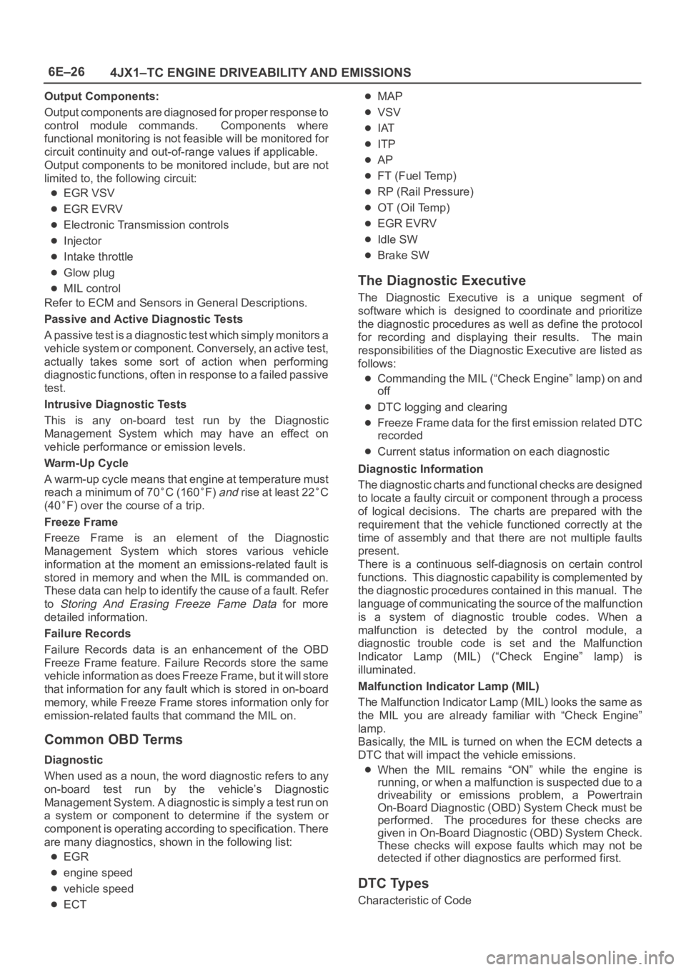
6E–26
4JX1–TC ENGINE DRIVEABILITY AND EMISSIONS
Output Components:
Output components are diagnosed for proper response to
control module commands. Components where
functional monitoring is not feasible will be monitored for
circuit continuity and out-of-range values if applicable.
Output components to be monitored include, but are not
limited to, the following circuit:
EGR VSV
EGR EVRV
Electronic Transmission controls
Injector
Intake throttle
Glow plug
MIL control
Refer to ECM and Sensors in General Descriptions.
Passive and Active Diagnostic Tests
A passive test is a diagnostic test which simply monitors a
vehicle system or component. Conversely, an active test,
actually takes some sort of action when performing
diagnostic functions, often in response to a failed passive
test.
Intrusive Diagnostic Tests
This is any on-board test run by the Diagnostic
Management System which may have an effect on
vehicle performance or emission levels.
Warm-Up Cycle
A warm-up cycle means that engine at temperature must
reach a minimum of 70
C (160F) and rise at least 22C
(40
F) over the course of a trip.
Freeze Frame
Freeze Frame is an element of the Diagnostic
Management System which stores various vehicle
information at the moment an emissions-related fault is
stored in memory and when the MIL is commanded on.
These data can help to identify the cause of a fault. Refer
to
Storing And Erasing Freeze Fame Data for more
detailed information.
Failure Records
Failure Records data is an enhancement of the OBD
Freeze Frame feature. Failure Records store the same
vehicle information as does Freeze Frame, but it will store
that information for any fault which is stored in on-board
memory, while Freeze Frame stores information only for
emission-related faults that command the MIL on.
Common OBD Terms
Diagnostic
When used as a noun, the word diagnostic refers to any
on-board test run by the vehicle’s Diagnostic
Management System. A diagnostic is simply a test run on
a system or component to determine if the system or
component is operating according to specification. There
are many diagnostics, shown in the following list:
EGR
engine speed
vehicle speed
ECT
MAP
VSV
IAT
ITP
AP
FT (Fuel Temp)
RP (Rail Pressure)
OT (Oil Temp)
EGR EVRV
Idle SW
Brake SW
The Diagnostic Executive
The Diagnostic Executive is a unique segment of
software which is designed to coordinate and prioritize
the diagnostic procedures as well as define the protocol
for recording and displaying their results. The main
responsibilities of the Diagnostic Executive are listed as
follows:
Commanding the MIL (“Check Engine” lamp) on and
off
DTC logging and clearing
Freeze Frame data for the first emission related DTC
recorded
Current status information on each diagnostic
Diagnostic Information
The diagnostic charts and functional checks are designed
to locate a faulty circuit or component through a process
of logical decisions. The charts are prepared with the
requirement that the vehicle functioned correctly at the
time of assembly and that there are not multiple faults
present.
There is a continuous self-diagnosis on certain control
functions. This diagnostic capability is complemented by
the diagnostic procedures contained in this manual. The
language of communicating the source of the malfunction
is a system of diagnostic trouble codes. When a
malfunction is detected by the control module, a
diagnostic trouble code is set and the Malfunction
Indicator Lamp (MIL) (“Check Engine” lamp) is
illuminated.
Malfunction Indicator Lamp (MIL)
The Malfunction Indicator Lamp (MIL) looks the same as
the MIL you are already familiar with “Check Engine”
lamp.
Basically, the MIL is turned on when the ECM detects a
DTC that will impact the vehicle emissions.
When the MIL remains “ON” while the engine is
running, or when a malfunction is suspected due to a
driveability or emissions problem, a Powertrain
On-Board Diagnostic (OBD) System Check must be
performed. The procedures for these checks are
given in On-Board Diagnostic (OBD) System Check.
These checks will expose faults which may not be
detected if other diagnostics are performed first.
DTC Types
Characteristic of Code
Page 1934 of 6000
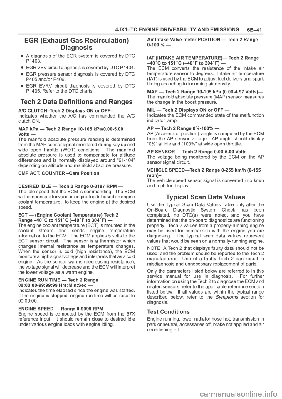
6E–41 4JX1–TC ENGINE DRIVEABILITY AND EMISSIONS
EGR (Exhaust Gas Recirculation)
Diagnosis
A diagnosis of the EGR system is covered by DTC
P1403.
EGR VSV circuit diagnosis is covered by DTC P1404.
EGR pressure sensor diagnosis is covered by DTC
P405 and/or P406.
EGR EVRV circuit diagnosis is covered by DTC
P1405. Refer to the DTC charts.
Tech 2 Data Definitions and Ranges
A/C CLUTCH–Tech 2 Displays ON or OFF–
Indicates whether the A/C has commanded the A/C
clutch ON.
MAP kPa — Tech 2 Range 10-105 kPa/0.00-5.00
Vo l t s —
The manifold absolute pressure reading is determined
from the MAP sensor signal monitored during key up and
wide open throttle (WOT) conditions. The manifold
absolute pressure is used to compensate for altitude
differences and is normally displayed around “61-104”
depending on altitude and manifold absolute pressure.
CMP ACT. COUNTER –Cam Position
DESIRED IDLE — Tech 2 Range 0-3187 RPM —
The idle speed that the ECM is commanding. The ECM
will compensate for various engine loads based on engine
coolant temperature, to keep the engine at the desired
speed.
ECT — (Engine Coolant Temperature) Tech 2
Range –40
C to 151C (–40F to 304F) —
The engine coolant temperature (ECT) is mounted in the
coolant stream and sends engine temperature
information to the ECM. The ECM applies 5 volts to the
ECT sensor circuit. The sensor is a thermistor which
changes internal resistance as temperature changes.
When the sensor is cold (high resistance), the ECM
monitors a high signal voltage and interprets that as a cold
engine. As the sensor warms (decreasing resistance),
the voltage signal will decrease and the ECM will interpret
the lower voltage as a warm engine.
ENGINE RUN TIME — Tech 2 Range
00:00:00-99:99:99 Hrs:Min:Sec —
Indicates the time elapsed since the engine was started.
If the engine is stopped, engine run time will be reset to
00:00:00.
ENGINE SPEED — Range 0-9999 RPM —
Engine speed is computed by the ECM from the 57X
reference input. It should remain close to desired idle
under various engine loads with engine idling.Air Intake Valve meter POSITION — Tech 2 Range
0-100 % —
IAT (INTAKE AIR TEMPERATURE)— Tech 2 Range
–40
C to 151C (–40F to 304F) —
The ECM converts the resistance of the intake air
temperature sensor to degrees. Intake air temperature
(IAT) is used by the ECM to adjust fuel delivery and spark
timing according to incoming air density.
MAP — Tech 2 Range 10-105 kPa (0.00-4.97 Volts)—
The manifold absolute pressure (MAP) sensor measures
the change in the boost pressure.
MIL — Tech 2 Displays ON or OFF —
Indicates the ECM commanded state of the malfunction
indicator lamp.
AP — Tech 2 Range 0%-100% —
AP (Accelerator position) angle is computed by the ECM
from the AP sensor voltage. AP angle should display
“0%” at idle and “100%” at wide open throttle.
AP SENSOR — Tech 2 Range 0.00-5.00 Volts —
The voltage being monitored by the ECM on the AP
sensor signal circuit.
VEHICLE SPEED—Tech 2 Range 0-255 km/h (0-155
mph)–
The vehicle speed sensor signal is converted into km/h
and mph for display.
Typical Scan Data Values
Use the Typical Scan Data Values Table only after the
On-Board Diagnostic System Check has been
completed, no DTC(s) were noted, and you have
determined that the on-board diagnostics are functioning
properly. Tech 2 values from a properly-running engine
may be used for comparison with the engine you are
diagnosing. The typical scan data values represent
values that would be seen on a normally-running engine.
NOTE: A Tech 2 that displays faulty data should not be
used, and the problem should be reported to the Tech 2
manufacturer. Use of a faulty Tech 2 can result in
misdiagnosis and unnecessary replacement of parts.
Only the parameters listed below are referred to in this
service manual for use in diagnosis. For further
information on using the Tech 2 to diagnose the ECM and
related sensors, refer to the applicable reference section
listed below. If all values are within the typical range
described below, refer to the
Symptoms section for
diagnosis.
Test Conditions
Engine running, lower radiator hose hot, transmission in
park or neutral, accessaries off, brake not applied and air
conditioning off.
Page 1935 of 6000
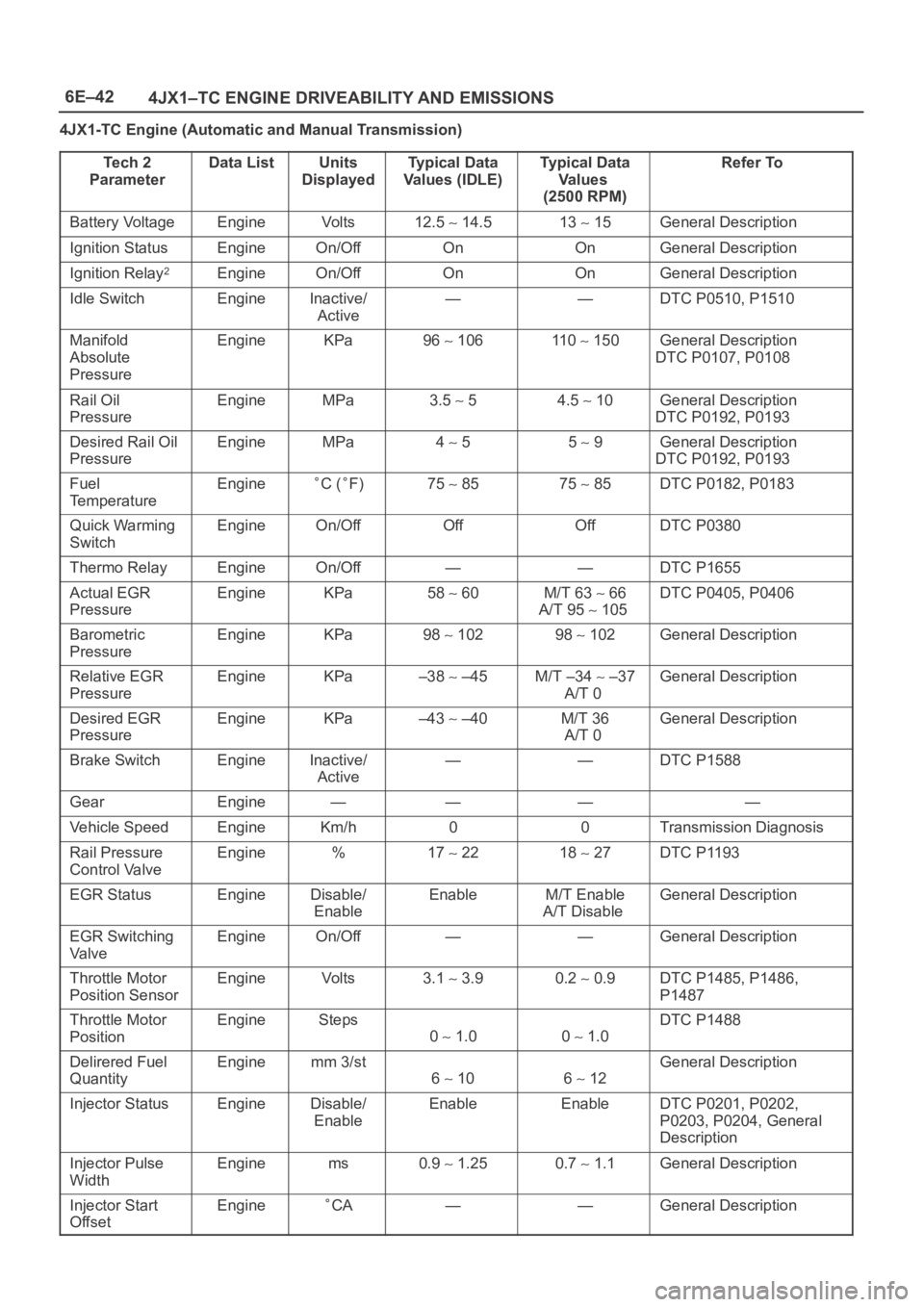
6E–42
4JX1–TC ENGINE DRIVEABILITY AND EMISSIONS
4JX1-TC Engine (Automatic and Manual Transmission)
Te c h 2
Parameter
Data ListUnits
DisplayedTy p i c a l D a t a
Values (IDLE)Typical Data
Va l u e s
(2500 RPM)Refer To
Battery VoltageEngineVo l t s12.5 14.513 15General Description
Ignition StatusEngineOn/OffOnOnGeneral Description
Ignition Relay2EngineOn/OffOnOnGeneral Description
Idle SwitchEngineInactive/
Active——DTC P0510, P1510
Manifold
Absolute
PressureEngineKPa96 106110 150General Description
DTC P0107, P0108
Rail Oil
PressureEngineMPa3.5 54.5 10General Description
DTC P0192, P0193
Desired Rail Oil
PressureEngineMPa4 55 9General Description
DTC P0192, P0193
Fuel
TemperatureEngineC (F)75 8575 85DTC P0182, P0183
Quick Warming
SwitchEngineOn/OffOffOffDTC P0380
Thermo RelayEngineOn/Off——DTC P1655
Actual EGR
PressureEngineKPa58 60M/T 63 66
A/T 95
105
DTC P0405, P0406
Barometric
PressureEngineKPa98 10298 102General Description
Relative EGR
PressureEngineKPa–38 –45M/T –34 –37
A/T 0General Description
Desired EGR
PressureEngineKPa–43 –40M/T 36
A/T 0General Description
Brake SwitchEngineInactive/
Active——DTC P1588
GearEngine————
Vehicle SpeedEngineKm/h00Transmission Diagnosis
Rail Pressure
Control ValveEngine%17 2218 27DTC P1193
EGR StatusEngineDisable/
EnableEnableM/T Enable
A/T DisableGeneral Description
EGR Switching
Va l v eEngineOn/Off——General Description
Throttle Motor
Position SensorEngineVo l t s3.1 3.90.2 0.9DTC P1485, P1486,
P1487
Throttle Motor
PositionEngineSteps
0 1.00 1.0
DTC P1488
Delirered Fuel
QuantityEnginemm 3/st
6 106 12
General Description
Injector StatusEngineDisable/
EnableEnableEnableDTC P0201, P0202,
P0203, P0204, General
Description
Injector Pulse
WidthEnginems0.9 1.250.7 1.1General Description
Injector Start
OffsetEngineCA——General Description
Page 1948 of 6000
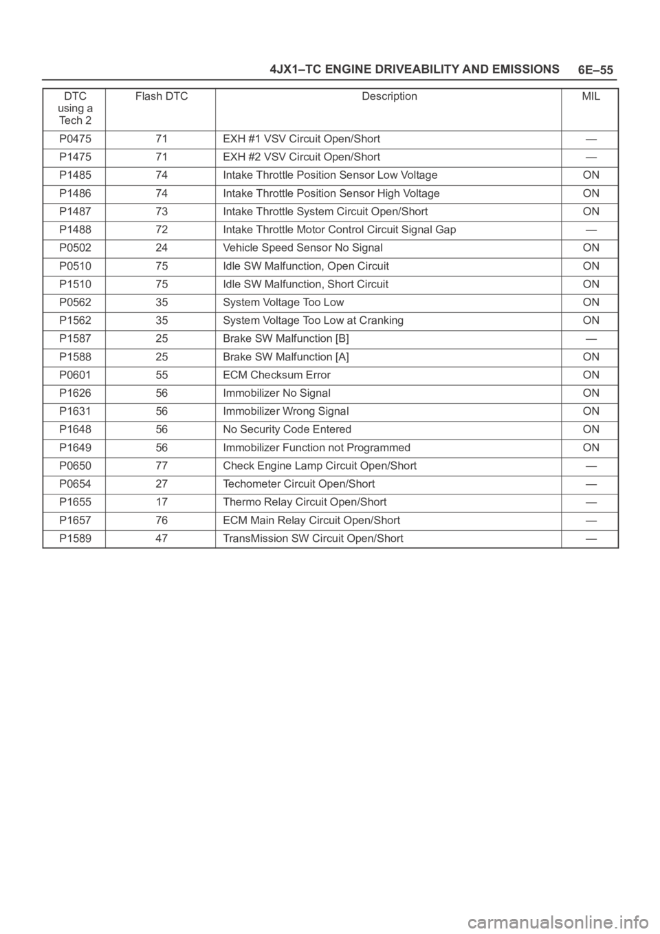
6E–55 4JX1–TC ENGINE DRIVEABILITY AND EMISSIONS
DTC
using a
Te c h 2Flash DTCDescriptionMIL
P047571EXH #1 VSV Circuit Open/Short—
P147571EXH #2 VSV Circuit Open/Short—
P148574Intake Throttle Position Sensor Low VoltageON
P148674Intake Throttle Position Sensor High VoltageON
P148773Intake Throttle System Circuit Open/ShortON
P148872Intake Throttle Motor Control Circuit Signal Gap—
P050224Vehicle Speed Sensor No SignalON
P051075Idle SW Malfunction, Open CircuitON
P151075Idle SW Malfunction, Short CircuitON
P056235System Voltage Too LowON
P156235System Voltage Too Low at CrankingON
P158725Brake SW Malfunction [B]—
P158825Brake SW Malfunction [A]ON
P060155ECM Checksum ErrorON
P162656Immobilizer No SignalON
P163156Immobilizer Wrong SignalON
P164856No Security Code EnteredON
P164956Immobilizer Function not ProgrammedON
P065077Check Engine Lamp Circuit Open/Short—
P065427Techometer Circuit Open/Short—
P165517Thermo Relay Circuit Open/Short—
P165776ECM Main Relay Circuit Open/Short—
P158947TransMission SW Circuit Open/Short—
Page 2246 of 6000
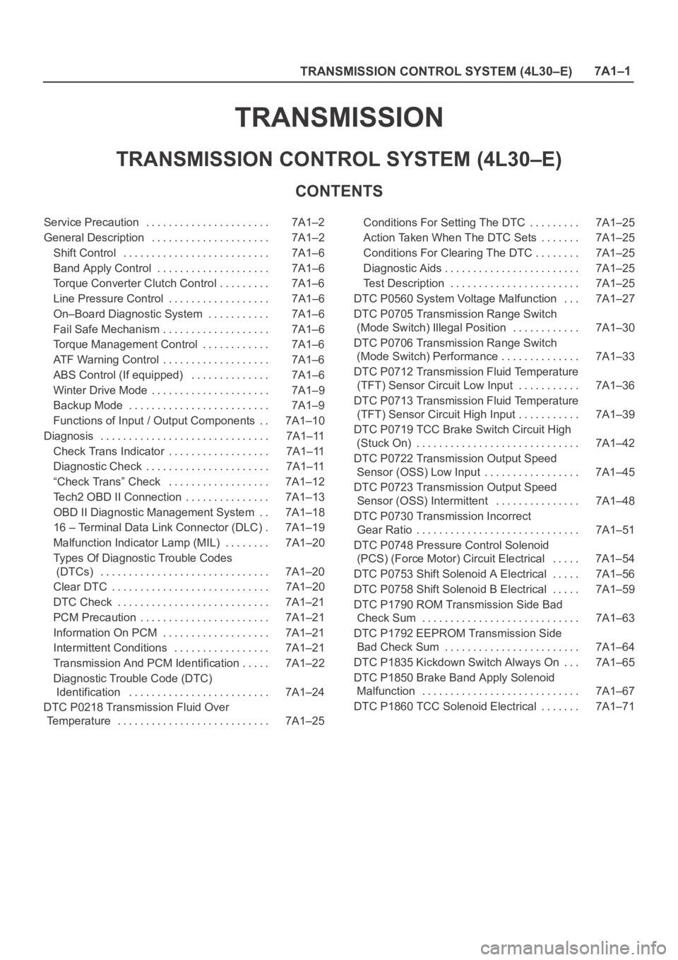
TRANSMISSION CONTROL SYSTEM (4L30–E)7A1–1
TRANSMISSION
TRANSMISSION CONTROL SYSTEM (4L30–E)
CONTENTS
Service Precaution 7A1–2. . . . . . . . . . . . . . . . . . . . . .
General Description 7A1–2. . . . . . . . . . . . . . . . . . . . .
Shift Control 7A1–6. . . . . . . . . . . . . . . . . . . . . . . . . .
Band Apply Control 7A1–6. . . . . . . . . . . . . . . . . . . .
Torque Converter Clutch Control 7A1–6. . . . . . . . .
Line Pressure Control 7A1–6. . . . . . . . . . . . . . . . . .
On–Board Diagnostic System 7A1–6. . . . . . . . . . .
Fail Safe Mechanism 7A1–6. . . . . . . . . . . . . . . . . . .
Torque Management Control 7A1–6. . . . . . . . . . . .
ATF Warning Control 7A1–6. . . . . . . . . . . . . . . . . . .
ABS Control (If equipped) 7A1–6. . . . . . . . . . . . . .
Winter Drive Mode 7A1–9. . . . . . . . . . . . . . . . . . . . .
Backup Mode 7A1–9. . . . . . . . . . . . . . . . . . . . . . . . .
Functions of Input / Output Components 7A1–10. .
Diagnosis 7A1–11. . . . . . . . . . . . . . . . . . . . . . . . . . . . . .
Check Trans Indicator 7A1–11. . . . . . . . . . . . . . . . . .
Diagnostic Check 7A1–11. . . . . . . . . . . . . . . . . . . . . .
“Check Trans” Check 7A1–12. . . . . . . . . . . . . . . . . .
Tech2 OBD II Connection 7A1–13. . . . . . . . . . . . . . .
OBD II Diagnostic Management System 7A1–18. .
16 – Terminal Data Link Connector (DLC) 7A1–19.
Malfunction Indicator Lamp (MIL) 7A1–20. . . . . . . .
Types Of Diagnostic Trouble Codes
(DTCs) 7A1–20. . . . . . . . . . . . . . . . . . . . . . . . . . . . . .
Clear DTC 7A1–20. . . . . . . . . . . . . . . . . . . . . . . . . . . .
DTC Check 7A1–21. . . . . . . . . . . . . . . . . . . . . . . . . . .
PCM Precaution 7A1–21. . . . . . . . . . . . . . . . . . . . . . .
Information On PCM 7A1–21. . . . . . . . . . . . . . . . . . .
Intermittent Conditions 7A1–21. . . . . . . . . . . . . . . . .
Transmission And PCM Identification 7A1–22. . . . .
Diagnostic Trouble Code (DTC)
Identification 7A1–24. . . . . . . . . . . . . . . . . . . . . . . . .
DTC P0218 Transmission Fluid Over
Temperature 7A1–25. . . . . . . . . . . . . . . . . . . . . . . . . . . Conditions For Setting The DTC 7A1–25. . . . . . . . .
Action Taken When The DTC Sets 7A1–25. . . . . . .
Conditions For Clearing The DTC 7A1–25. . . . . . . .
Diagnostic Aids 7A1–25. . . . . . . . . . . . . . . . . . . . . . . .
Test Description 7A1–25. . . . . . . . . . . . . . . . . . . . . . .
DTC P0560 System Voltage Malfunction 7A1–27. . .
DTC P0705 Transmission Range Switch
(Mode Switch) Illegal Position 7A1–30. . . . . . . . . . . .
DTC P0706 Transmission Range Switch
(Mode Switch) Performance 7A1–33. . . . . . . . . . . . . .
DTC P0712 Transmission Fluid Temperature
(TFT) Sensor Circuit Low Input 7A1–36. . . . . . . . . . .
DTC P0713 Transmission Fluid Temperature
(TFT) Sensor Circuit High Input 7A1–39. . . . . . . . . . .
DTC P0719 TCC Brake Switch Circuit High
(Stuck On) 7A1–42. . . . . . . . . . . . . . . . . . . . . . . . . . . . .
DTC P0722 Transmission Output Speed
Sensor (OSS) Low Input 7A1–45. . . . . . . . . . . . . . . . .
DTC P0723 Transmission Output Speed
Sensor (OSS) Intermittent 7A1–48. . . . . . . . . . . . . . .
DTC P0730 Transmission Incorrect
Gear Ratio 7A1–51. . . . . . . . . . . . . . . . . . . . . . . . . . . . .
DTC P0748 Pressure Control Solenoid
(PCS) (Force Motor) Circuit Electrical 7A1–54. . . . .
DTC P0753 Shift Solenoid A Electrical 7A1–56. . . . .
DTC P0758 Shift Solenoid B Electrical 7A1–59. . . . .
DTC P1790 ROM Transmission Side Bad
Check Sum 7A1–63. . . . . . . . . . . . . . . . . . . . . . . . . . . .
DTC P1792 EEPROM Transmission Side
Bad Check Sum 7A1–64. . . . . . . . . . . . . . . . . . . . . . . .
DTC P1835 Kickdown Switch Always On 7A1–65. . .
DTC P1850 Brake Band Apply Solenoid
Malfunction 7A1–67. . . . . . . . . . . . . . . . . . . . . . . . . . . .
DTC P1860 TCC Solenoid Electrical 7A1–71. . . . . . .
Page 2247 of 6000
7A1–2
TRANSMISSION CONTROL SYSTEM (4L30–E)
Service Precaution
WARNING: IF SO EQUIPPED WITH A
SUPPLEMENTAL RESTRAINT SYSTEM (SRS),
REFER TO THE SRS COMPONENT AND WIRING
LOCATION VIEW IN ORDER TO DETERMINE
WHETHER YOU ARE PERFORMING SERVICE ON OR
NEAR THE SRS COMPONENTS OR THE SRS
WIRING. WHEN YOU ARE PERFORMING SERVICE
ON OR NEAR THE SRS COMPONENTS OR THE SRS
WIRING, REFER TO THE SRS SERVICE
INFORMATION. FAILURE TO FOLLOW WARNINGS
COULD RESULT IN POSSIBLE AIR BAG
DEPLOYMENT, PERSONAL INJURY, OR
OTHERWISE UNNEEDED SRS SYSTEM REPAIRS.
CAUTION: Always use the correct fastener in the
proper location. When you replace a fastener, use
ONLY the exact part number for that application.
ISUZU will call out those fasteners that require a
replacement after removal. ISUZU will also call out
the fasteners that require thread lockers or thread
sealant. UNLESS OTHERWISE SPECIFIED, do not
use supplemental coatings (Paints, greases, or other
corrosion inhibitors) on threaded fasteners or
fastener joint interfaces. Generally, such coatings
adversely affect the fastener torque and the joint
clamping force, and may damage the fastener. When
you install fasteners, use the correct tightening
sequence and specifications. Following these
instructions can help you avoid damage to parts and
systems.
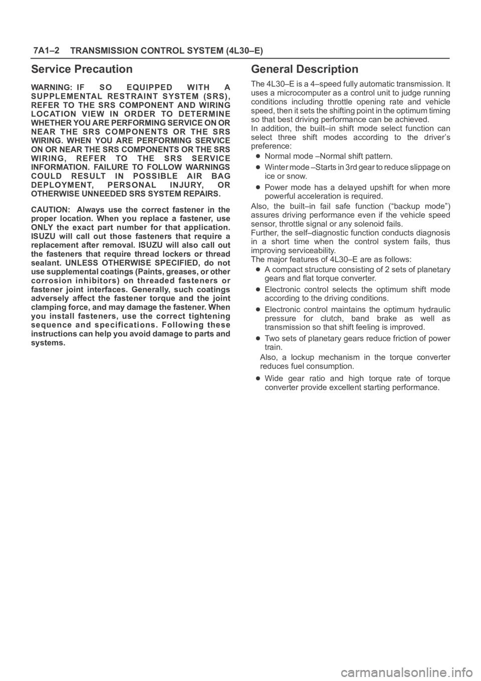
General Description
The 4L30–E is a 4–speed fully automatic transmission. It
uses a microcomputer as a control unit to judge running
conditions including throttle opening rate and vehicle
speed, then it sets the shifting point in the optimum timing
so that best driving performance can be achieved.
In addition, the built–in shift mode select function can
select three shift modes according to the driver’s
preference:
Normal mode –Normal shift pattern.
Winter mode –Starts in 3rd gear to reduce slippage on
ice or snow.
Power mode has a delayed upshift for when more
powerful acceleration is required.
Also, the built–in fail safe function (“backup mode”)
assures driving performance even if the vehicle speed
sensor, throttle signal or any solenoid fails.
Further, the self–diagnostic function conducts diagnosis
in a short time when the control system fails, thus
improving serviceability.
The major features of 4L30–E are as follows:
A compact structure consisting of 2 sets of planetary
gears and flat torque converter.
Electronic control selects the optimum shift mode
according to the driving conditions.
Electronic control maintains the optimum hydraulic
pressure for clutch, band brake as well as
transmission so that shift feeling is improved.
Two sets of planetary gears reduce friction of power
train.
Also, a lockup mechanism in the torque converter
reduces fuel consumption.
Wide gear ratio and high torque rate of torque
converter provide excellent starting performance.
Page 2255 of 6000
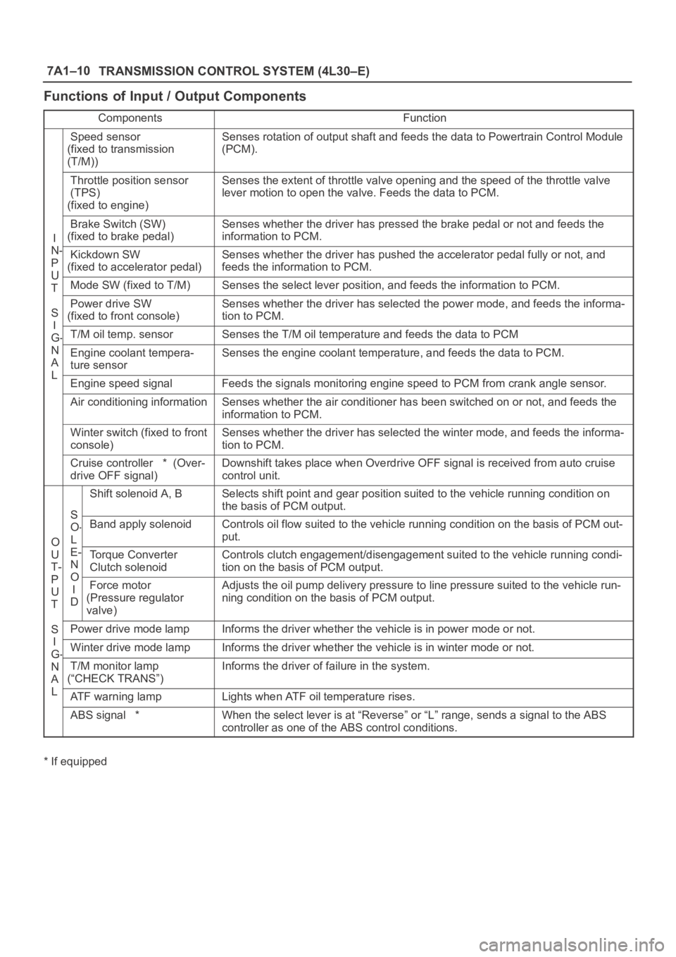
7A1–10
TRANSMISSION CONTROL SYSTEM (4L30–E)
Functions of Input / Output Components
ComponentsFunction
Speed sensor
(fixed to transmission
(T/M))Senses rotation of output shaft and feeds the data to Powertrain Control Module
(PCM).
Throttle position sensor
(TPS)
(fixed to engine)Senses the extent of throttle valve opening and the speed of the throttle valve
lever motion to open the valve. Feeds the data to PCM.
I
N
Brake Switch (SW)
(fixed to brake pedal)Senses whether the driver has pressed the brake pedal or not and feeds the
information to PCM.
N-
P
U
Kickdown SW
(fixed to accelerator pedal)Senses whether the driver has pushed the accelerator pedal fully or not, and
feeds the information to PCM.
U
TMode SW (fixed to T/M)Senses the select lever position, and feeds the information to PCM.
S
I
Power drive SW
(fixed to front console)Senses whether the driver has selected the power mode, and feeds the informa-
tion to PCM.
I
G-T/M oil temp. sensorSenses the T/M oil temperature and feeds the data to PCM
N
A
L
Engine coolant tempera-
ture sensorSenses the engine coolant temperature, and feeds the data to PCM.
LEngine speed signalFeeds the signals monitoring engine speed to PCM from crank angle sensor.
Air conditioning informationSenses whether the air conditioner has been switched on or not, and feeds the
information to PCM.
Winter switch (fixed to front
console)Senses whether the driver has selected the winter mode, and feeds the informa-
tion to PCM.
Cruise controller * (Over-
drive OFF signal)Downshift takes place when Overdrive OFF signal is received from auto cruise
control unit.
S
Shift solenoid A, BSelects shift point and gear position suited to the vehicle running condition on
the basis of PCM output.
O
S
O-
L
Band apply solenoidControls oil flow suited to the vehicle running condition on the basis of PCM out-
put.
O
U
T-
P
E-
N
O
Torque Converter
Clutch solenoidControls clutch engagement/disengagement suited to the vehicle running condi-
tion on the basis of PCM output.
P
U
T
O
I
DForce motor
(Pressure regulator
valve)Adjusts the oil pump delivery pressure to line pressure suited to the vehicle run-
ning condition on the basis of PCM output.
S
I
Power drive mode lampInforms the driver whether the vehicle is in power mode or not.
I
G-Winter drive mode lampInforms the driver whether the vehicle is in winter mode or not.G
N
A
L
T/M monitor lamp
(“CHECK TRANS”)Informs the driver of failure in the system.
LATF warning lampLights when ATF oil temperature rises.
ABS signal *When the select lever is at “Reverse” or “L” range, sends a signal to the ABS
controller as one of the ABS control conditions.
* If equipped