Page 2269 of 6000

7A1–24
TRANSMISSION CONTROL SYSTEM (4L30–E)
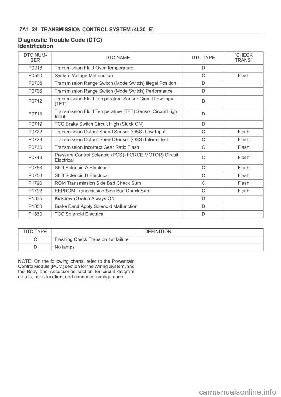
Diagnostic Trouble Code (DTC)
Identification
DTC NUM-
BERDTC NAMEDTC TYPE“CHECK
TRANS”
P0218Transmission Fluid Over TemperatureD
P0560System Voltage MalfunctionCFlash
P0705Transmission Range Switch (Mode Switch) Illegal PositionD
P0706Transmission Range Switch (Mode Switch) PerformanceD
P0712Transmission Fluid Temperature Sensor Circuit Low Input
(TFT)D
P0713Transmission Fluid Temperature (TFT) Sensor Circuit High
InputD
P0719TCC Brake Switch Circuit High (Stuck ON)D
P0722Transmission Output Speed Sensor (OSS) Low InputCFlash
P0723Transmission Output Speed Sensor (OSS) IntermittentCFlash
P0730Transmission Incorrect Gear Ratio FlashCFlash
P0748Pressure Control Solenoid (PCS) (FORCE MOTOR) Circuit
ElectricalCFlash
P0753Shift Solenoid A ElectricalCFlash
P0758Shift Solenoid B ElectricalCFlash
P1790ROM Transmission Side Bad Check SumCFlash
P1792EEPROM Transmission Side Bad Check SumCFlash
P1835Kickdown Switch Always OND
P1850Brake Band Apply Solenoid MalfunctionD
P1860TCC Solenoid ElectricalD
DTC TYPEDEFINITION
CFlashing Check Trans on 1st failure
DNo lamps
NOTE: On the following charts, refer to the Powertrain
Control Module (PCM) section for the Wiring System, and
the Body and Accessories section for circuit diagram
details, parts location, and connector configuration.
Page 2867 of 6000
0.5
O
0.5
BR/B0.5
BR/R0.5
BR/R
0.5
BR/B 5.0
W
0.85
G/W
0.85
G/Y
0.5
G/Y 0.85
G/YC-14 15A
STOP,
A/T CONT
ACTUATOR BRAKE
SW
INDICATOR
LIGHT
(METER)
CRUISE CONTROL UNIT
BATT.(+)
STOP
LIGHT
2
B-9
3.0
B/Y
0.5
L/YC-10 10A
METER,GAUGE STARTER SW
(IG1)
B-131B-13
B-13H-73B-13
3C-37
7122 4
C-37
4
8B-914H-80.5
BR/W
0.5
BR/W
C-37
1
11H-70.5
BR
0.5
BR
C-37
2
19H-7
7
B-915
B-9
6
B-914
B-914H-26
H-32
0.5
L/Y
0.5
B/O
0.3
B/O0.5
GR/L
0.3
GR/L
0.5
GR/L0.5
LG/W0.5
LG/W
13
B-915H-2618
I-926I-9(W/T.O.D.)
VEHICLE
SPEED SENSOR
(3)
PCM
(F10)
19
I-9
CRUISE
CRUISE
MAIN
16
I-915I-9
17
I-9
5
B-97H-8
9
B-92H-811H-10
CRUISE
CRUISE
MAINH-266
D08RW662
Page 2870 of 6000
0.5
O
0.5
BR/B0.5
BR/R0.5
BR/R
0.5
BR/B 5.0
W
0.85
G/W
0.85
G/Y
0.5
G/Y 0.85
G/YC-14 15A
STOP,
A/T CONT
ACTUATOR BRAKE
SW
INDICATOR
LIGHT
(METER)
CRUISE CONTROL UNIT
BATT.(+)
STOP
LIGHT
2
B-9
3.0
B/Y
0.5
L/YC-10 10A
METER,GAUGE STARTER SW
(IG1)
B-131B-13
B-13H-123B-13
3C-37
106 2 4
C-37
4
8B-97H-120.5
BR/W
0.5
BR/W
C-37
1
3H-120.5
BR
0.5
BR
C-37
2
15H-12
7
B-915
B-9
6
B-914
B-913H-48
H-32
0.5
L/Y
0.3
B/O
0.3
B/O0.3
GR/L
0.3
GR/L
0.5
GR/L0.5
LG/W0.5
LG/W
13
B-912H-48VEHICLE
SPEED SENSOR
(3)
PCM
(F10) 16
I-915I-9
17
I-9
5
B-92H-7
9
B-98H-811H-10
CRUISE
CRUISE
MAINH-2510
D08RW958
Page 2878 of 6000
2.0
Y/G2.0
W/G 3.0
W/G
0.5
LG FL-6 40A
ABS
F-9 20A
ABS
INDICATOR
LIGHT(METER)
BRAKE
SW STOP
LIGHT
SW
ELECTRONIC
HYDRAULIC
CONTROL UNIT
4WD CONTROL
UNIT(19)
14C-413C-4
3.0
B/Y3.0
B/Y
0.85
L/W0.5
L/W0.5
L/W
2.0
BC-4 10A
ELEC.IGN.
STARTER SW
(IG1)STARTER SW
(IG1)
C-10 10A
METER,GAUGE
I-9I-10156
I-9
2
H-26
H-1619
H-2718 16
5.0
W
0.85
G/W C-14 15A
STOP,A/T CONT. BATT.(+) BATT.(+)
STOP LIGHT
10C-430.85
G/W (W/CRUISE CONTROL) 0.85
G/W
0.85
G/Y
0.85
G/Y 0.85
G/Y
0.85
G/Y
B-131
B-13
4
B-14
H-131
B-14
2G-
SENSOR
26C-4 0.5
L/W
0.5
Y/B
0.5
Y/B
B-252
B-25
1
H-151
8C-4
6
C-39
FENDER-RH
H-131
C-4
15
16C-4 0.5
L/Y
0.5
L/Y
0.5
Y
0.5
Y
A
2.0
B(DIESEL)
5
C-39
FENDER-RH
C-4
15
2.0
B
C-85
ENG.ROOM-FRT
C-4 GROUND GROUND GROUND BATTERY BATTERY G-SENSOR POWER
SUPPLYSILA BRAKE LIGHT
SWITCH
12
4WDABS
D08RW601
Page 2885 of 6000
2.0
Y/G2.0
W/G 3.0
W/G
0.5
LG FL-6 40A
ABS
F-9 20A
ABS
INDICATOR
LIGHT(METER)
BRAKE
SWITCH STOP
LIGHT
SWITCH
ELECTRONIC
HYDRAULIC
CONTROL
UNIT
4WD CONTROL
UNIT(19)
14C-413C-4
3.0
B/Y3.0
B/Y
0.85
L/W0.5
L/W0.5
L/W
2.0
BC-4 10A
ELEC.IGN.
STARTER SW
(IG1)STARTER SW
(IG1)
C-10 10A
METER,GAUGE
I-9I-1015 10
I-9
18
H-25
H-1622
H-2518 16
5.0
W
0.85
G/W C-14 15A
STOP,A/T CONT. BATT.(+) BATT.(+)
STOP LIGHT
10C-420.85
G/W (W/CRUISE CONTROL) 0.85
G/W
0.85
G/Y
0.85
G/Y 0.85
G/Y
0.85
G/Y
B-131
B-13
4
B-14
H-131
B-14
2
G-
SENSOR
26C-4 0.5
L/W
0.5
Y/B
0.5
Y/B
B-252
B-25
1
H-154
8C-4
6
C-39
FENDER-RH
H-125
C-4
15
16C-4 0.5
L/Y
0.5
L/Y
0.5
Y
0.5
Y
A
2.0
B
C-85
ENG. ROOM-FRT
C-4 GROUND GROUND BATTERY BATTERY G-SENSOR POWER
SUPPLYSILA BRAKE LIGHT
SWITCH
12
4WDABS
2.0
B
5
C-39
FENDER-RH
C-4
15GROUND
(4JG2)
D08RW793
Page 3178 of 6000

METER AND GAUGE8E–1
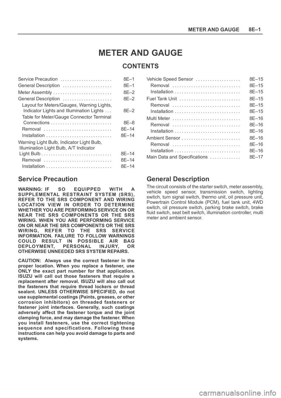
METER AND GAUGE
CONTENTS
Service Precaution 8E–1. . . . . . . . . . . . . . . . . . . . . .
General Description 8E–1. . . . . . . . . . . . . . . . . . . . .
Meter Assembly 8E–2. . . . . . . . . . . . . . . . . . . . . . . . .
General Description 8E–2. . . . . . . . . . . . . . . . . . . . .
Layout for Meters/Gauges, Warning Lights,
Indicator Lights and Illumination Lights 8E–2. . .
Table for Meter/Gauge Connector Terminal
Connections 8E–8. . . . . . . . . . . . . . . . . . . . . . . . . .
Removal 8E–14. . . . . . . . . . . . . . . . . . . . . . . . . . . . .
Installation 8E–14. . . . . . . . . . . . . . . . . . . . . . . . . . . .
Warning Light Bulb, Indicator Light Bulb,
Illumination Light Bulb, A/T Indicator
Light Bulb 8E–14. . . . . . . . . . . . . . . . . . . . . . . . . . . . . .
Removal 8E–14. . . . . . . . . . . . . . . . . . . . . . . . . . . . .
Installation 8E–14. . . . . . . . . . . . . . . . . . . . . . . . . . . . Vehicle Speed Sensor 8E–15. . . . . . . . . . . . . . . . . . .
Removal 8E–15. . . . . . . . . . . . . . . . . . . . . . . . . . . . .
Installation 8E–15. . . . . . . . . . . . . . . . . . . . . . . . . . . .
Fuel Tank Unit 8E–15. . . . . . . . . . . . . . . . . . . . . . . . . .
Removal 8E–15. . . . . . . . . . . . . . . . . . . . . . . . . . . . .
Installation 8E–15. . . . . . . . . . . . . . . . . . . . . . . . . . . .
Multi Meter 8E–16. . . . . . . . . . . . . . . . . . . . . . . . . . . . .
Removal 8E–16. . . . . . . . . . . . . . . . . . . . . . . . . . . . .
Installation 8E–16. . . . . . . . . . . . . . . . . . . . . . . . . . . .
Ambient Sensor 8E–16. . . . . . . . . . . . . . . . . . . . . . . . .
Removal 8E–16. . . . . . . . . . . . . . . . . . . . . . . . . . . . .
Installation 8E–16. . . . . . . . . . . . . . . . . . . . . . . . . . . .
Main Data and Specifications 8E–17. . . . . . . . . . . . .
Service Precaution
WARNING: IF SO EQUIPPED WITH A
SUPPLEMENTAL RESTRAINT SYSTEM (SRS),
REFER TO THE SRS COMPONENT AND WIRING
LOCATION VIEW IN ORDER TO DETERMINE
WHETHER YOU ARE PERFORMING SERVICE ON OR
NEAR THE SRS COMPONENTS OR THE SRS
WIRING. WHEN YOU ARE PERFORMING SERVICE
ON OR NEAR THE SRS COMPONENTS OR THE SRS
WIRING, REFER TO THE SRS SERVICE
INFORMATION. FAILURE TO FOLLOW WARNINGS
COULD RESULT IN POSSIBLE AIR BAG
DEPLOYMENT, PERSONAL INJURY, OR
OTHERWISE UNNEEDED SRS SYSTEM REPAIRS.
CAUTION: Always use the correct fastener in the
proper location. When you replace a fastener, use
ONLY the exact part number for that application.
ISUZU will call out those fasteners that require a
replacement after removal. ISUZU will also call out
the fasteners that require thread lockers or thread
sealant. UNLESS OTHERWISE SPECIFIED, do not
use supplemental coatings (Paints, greases, or other
corrosion inhibitors) on threaded fasteners or
fastener joint interfaces. Generally, such coatings
adversely affect the fastener torque and the joint
clamping force, and may damage the fastener. When
you install fasteners, use the correct tightening
sequence and specifications. Following these
instructions can help you avoid damage to parts and
systems.
General Description
The circuit consists of the starter switch, meter assembly,
vehicle speed sensor, transmission switch, lighting
switch, turn signal switch, thermo unit, oil pressure unit,
Powertrain Control Module (PCM), fuel tank unit, 4WD
switch, oil pressure switch, parking brake switch, brake
fluid switch, seat belt switch, illumination controller, multi
meter and ambient sensor.
Page 3946 of 6000

DIFFERENTIAL (FRONT) 4A1–6
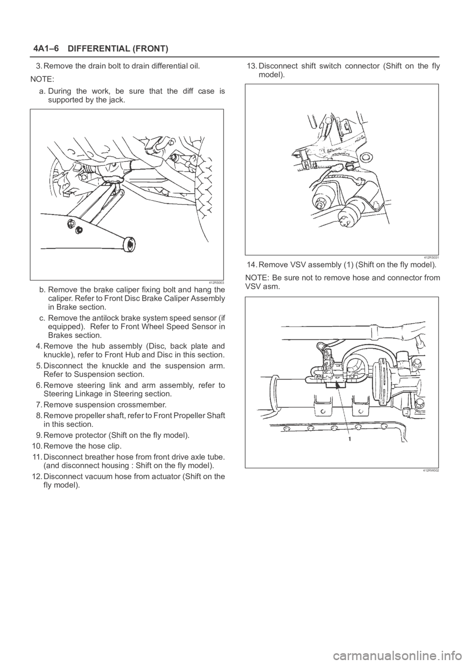
3. Remove the drain bolt to drain differential oil.
NOTE:
a. During the work, be sure that the diff case is
supported by the jack.
412RS003
b. Remove the brake caliper fixing bolt and hang the
caliper. Refer to Front Disc Brake Caliper Assembly
in Brake section.
c. Remove the antilock brake system speed sensor (if
equipped). Refer to Front Wheel Speed Sensor in
Brakes section.
4. Remove the hub assembly (Disc, back plate and
knuckle), refer to Front Hub and Disc in this section.
5. Disconnect the knuckle and the suspension arm.
Refer to Suspension section.
6. Remove steering link and arm assembly, refer to
Steering Linkage in Steering section.
7. Remove suspension crossmember.
8. Remove propeller shaft, refer to Front Propeller Shaft
in this section.
9. Remove protector (Shift on the fly model).
10. Remove the hose clip.
11. Disconnect breather hose from front drive axle tube.
(and disconnect housing : Shift on the fly model).
12. Disconnect vacuum hose from actuator (Shift on the
fly model).13. Disconnect shift switch connector (Shift on the fly
model).
412RS031
14. Remove VSV assembly (1) (Shift on the fly model).
NOTE: Be sure not to remove hose and connector from
VSV asm.
412RW002
Page 3973 of 6000

4A2A–4
DIFFERENTIAL (REAR 220mm)
Axle Housing
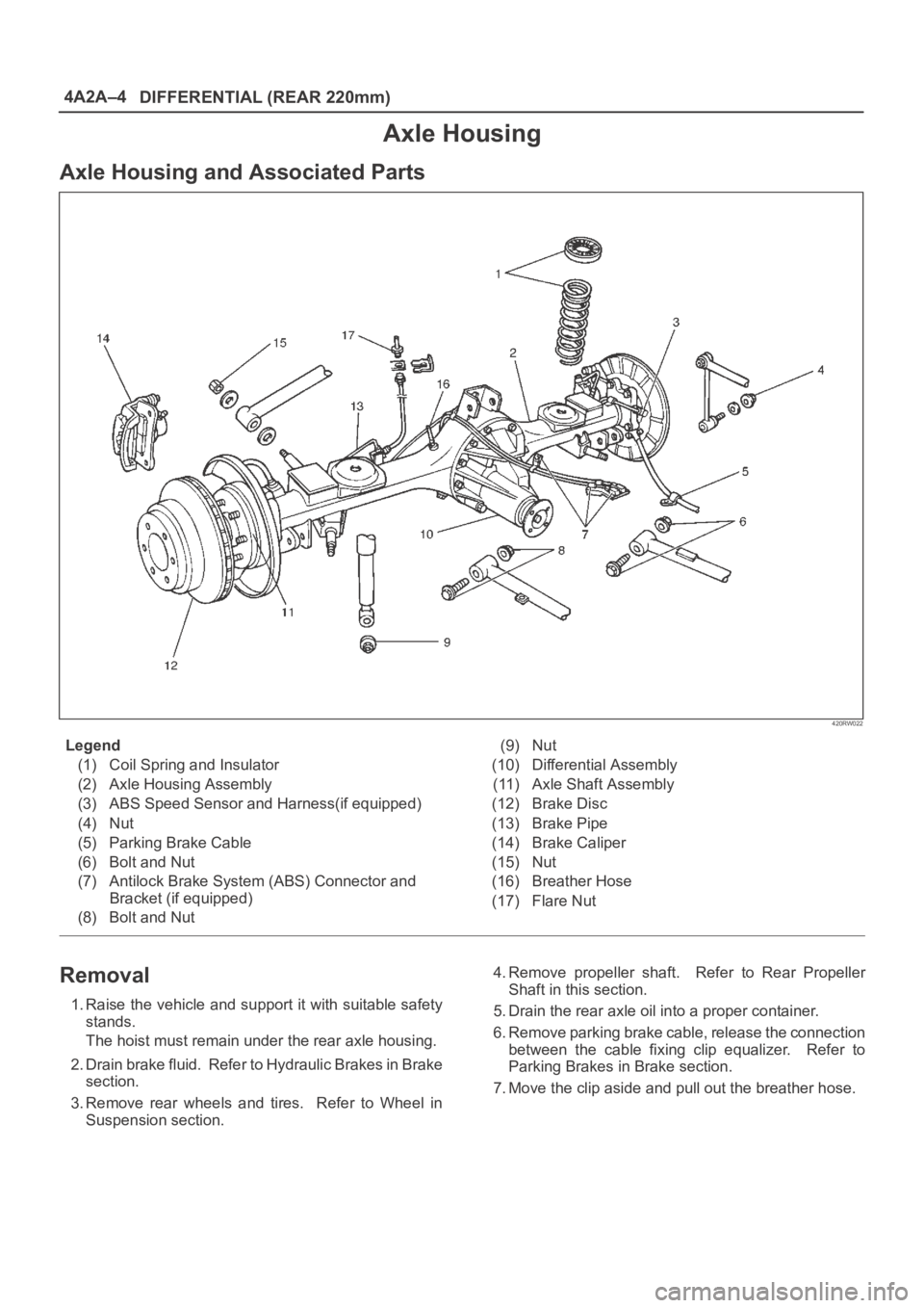
Axle Housing and Associated Parts
420RW022
Legend
(1) Coil Spring and Insulator
(2) Axle Housing Assembly
(3) ABS Speed Sensor and Harness(if equipped)
(4) Nut
(5) Parking Brake Cable
(6) Bolt and Nut
(7) Antilock Brake System (ABS) Connector and
Bracket (if equipped)
(8) Bolt and Nut(9) Nut
(10) Differential Assembly
(11) Axle Shaft Assembly
(12) Brake Disc
(13) Brake Pipe
(14) Brake Caliper
(15) Nut
(16) Breather Hose
(17) Flare Nut
Removal
1. Raise the vehicle and support it with suitable safety
stands.
The hoist must remain under the rear axle housing.
2. Drain brake fluid. Refer to Hydraulic Brakes in Brake
section.
3. Remove rear wheels and tires. Refer to Wheel in
Suspension section.4. Remove propeller shaft. Refer to Rear Propeller
Shaft in this section.
5. Drain the rear axle oil into a proper container.
6. Remove parking brake cable, release the connection
between the cable fixing clip equalizer. Refer to
Parking Brakes in Brake section.
7. Move the clip aside and pull out the breather hose.