Page 4019 of 6000
4A2B–12DIFFERENTIAL (REAR 244mm)
Differential Assembly
Differential Assembly and Associated Parts
425RY00016
Legend
(1) Bolt and Nut
(2) Axle Shaft Assembly(3) Parking Brake Cable
(4) Differential Assembly
(5) Nut
Removal
1. Jack up and support the frame with stands.
2. Remove the wheel and tire. Refer to Wheel in
Steering section.
3. Drain the differential oil.
4. Remove the propeller shaft. Refer to Rear Propeller
Shaft in this section.
5. Remove the ABS speed sensor. Refer to Anti–lock
Brake System in Brakes section.6. Remove the parking brake cable fastening clip and
disconnect the equalizer section. Refer to Parking
Brakes in Brake section.
7. Remove the bearing holder fixing nuts.
8. Remove axle shaft assembly, be sure not to damage
the oil seal by axle shaft.
9. Remove differential carrier mounting bolts and nuts.
10. Remove differential assembly.
Page 4089 of 6000
DRIVE LINE CONTROL SYSTEM (TOD) 4B2–6
High-Low Planetary Gear Set
Establishes an auxiliary transmission mechanism. When
the transfer shift lever is set to the 2H or TOD position, the
reduction gear ratio is 1.000 and the corresponding
driving force is generated. When the transfer shift lever is
set to the 4L position, the reduction gear ratio is 2.480 and
the corresponding driving force is generated.
262RW030
4H and 4L Switch
Detects the shift position of the transfer from the
movement of the transfer lever and outputs signals to the
TOD control unit.
261RW002
Transfer Connector
Transmits the input and output signals of the speed
sensors, electromagnetic coil, and 4H and 4L switche to
the vehicle harness. A waterproof 12-pin type is used.
261RW046
TOD Indicator Lamps (on the instrument
panel)
Inform the following items.
Bulb check
Drive mode
ABS IN status
BRAKE ON status
821RW049
Page 4120 of 6000
4B2–37 DRIVE LINE CONTROL SYSTEM (TOD)
No.NAMECONTENTS
1VIGPower supply (IG)
2N.CNot used
34WD OUT4WD signal output
4SOL (+)Electromagnetic solenoid
5ADC (+)Axle disconnect output
6LIGHTING SWLighting SW input
7BRAKEBrake SW input
84H SW4H SW input
94L SW4L SW input
10AXEL SWAXEL SW input
11ABS INOperation signal input
12TOD SWTOD SW input
13DIAGSelf-diagnosis input
14D-G MAPD-G MAP recognition input (Only V6 engine)
15Ref.Vehicle speed sensor supply
16N.CNot used
17N.CNot used
18COM (–)Vehicle speed sensor GND
19S-GNDSensor GND
20P-GNDPower GND
21TPSThrottle position sensor
22TECH 2TECH 2 output
23Rer. SigRear vehicle speed sensor input
24Frt. SigFront vehicle speed sensor input
25IND.a4WD display signal a
26IND.b4WD display signal b
27IND.c4WD display signal c
28IND.AUTOAUTO display output
29IND RrRear display output
30CHECKTOD warning lamp
Page 4122 of 6000

4B2–39 DRIVE LINE CONTROL SYSTEM (TOD)
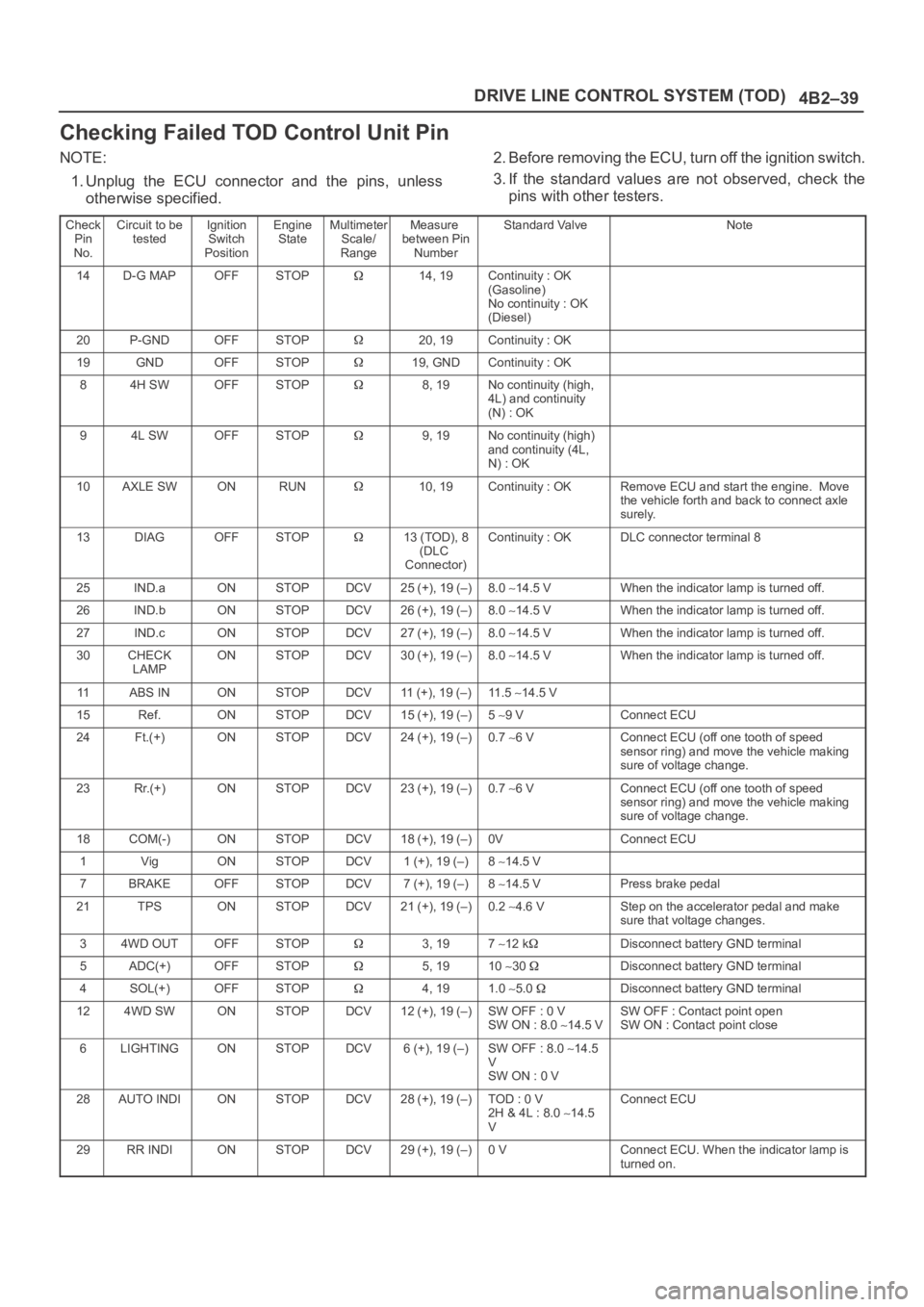
Checking Failed TOD Control Unit Pin
NOTE:
1. Unplug the ECU connector and the pins, unless
otherwise specified.2. Before removing the ECU, turn off the ignition switch.
3. If the standard values are not observed, check the
pins with other testers.
Check
Pin
No.Circuit to be
testedIgnition
Switch
PositionEngine
StateMultimeter
Scale/
RangeMeasure
between Pin
NumberStandard ValveNote
14D-G MAPOFFSTOP14, 19Continuity : OK
(Gasoline)
No continuity : OK
(Diesel)
20P-GNDOFFSTOP20, 19Continuity : OK
19GNDOFFSTOP19, GNDContinuity : OK
84H SWOFFSTOP8, 19No continuity (high,
4L) and continuity
(N) : OK
94L SWOFFSTOP9, 19No continuity (high)
and continuity (4L,
N) : OK
10AXLE SWONRUN10, 19Continuity : OKRemove ECU and start the engine. Move
the vehicle forth and back to connect axle
surely.
13DIAGOFFSTOP13 (TOD), 8
(DLC
Connector)Continuity : OKDLC connector terminal 8
25IND.aONSTOPDCV25 (+), 19 (–)8.0 14.5 VWhen the indicator lamp is turned off.
26IND.bONSTOPDCV26 (+), 19 (–)8.0 14.5 VWhen the indicator lamp is turned off.
27IND.cONSTOPDCV27 (+), 19 (–)8.0 14.5 VWhen the indicator lamp is turned off.
30CHECK
LAMPONSTOPDCV30 (+), 19 (–)8.0 14.5 VWhen the indicator lamp is turned off.
11ABS INONSTOPDCV11 (+), 19 (–)11 . 5 14.5 V
15Ref.ONSTOPDCV15 (+), 19 (–)5 9 VConnect ECU
24Ft.(+)ONSTOPDCV24 (+), 19 (–)0.7 6 VConnect ECU (off one tooth of speed
sensor ring) and move the vehicle making
sure of voltage change.
23Rr.(+)ONSTOPDCV23 (+), 19 (–)0.7 6 VConnect ECU (off one tooth of speed
sensor ring) and move the vehicle making
sure of voltage change.
18COM(-)ONSTOPDCV18 (+), 19 (–)0VConnect ECU
1VigONSTOPDCV1 (+), 19 (–)8 14.5 V
7BRAKEOFFSTOPDCV7 (+), 19 (–)8 14.5 VPress brake pedal
21TPSONSTOPDCV21 (+), 19 (–)0.2 4.6 VStep on the accelerator pedal and make
sure that voltage changes.
34WD OUTOFFSTOP3, 197 12 kDisconnect battery GND terminal
5ADC(+)OFFSTOP5, 1910 30 Disconnect battery GND terminal
4SOL(+)OFFSTOP4, 191.0 5.0 Disconnect battery GND terminal
124WD SWONSTOPDCV12 (+), 19 (–)SW OFF : 0 V
SW ON : 8.0 14.5 VSW OFF : Contact point open
SW ON : Contact point close
6LIGHTINGONSTOPDCV6 (+), 19 (–)SW OFF : 8.0 14.5
V
SW ON : 0 V
28AUTO INDIONSTOPDCV28 (+), 19 (–)TOD : 0 V
2H & 4L : 8.0 14.5
VConnect ECU
29RR INDIONSTOPDCV29 (+), 19 (–)0 VConnect ECU. When the indicator lamp is
turned on.
Page 4199 of 6000

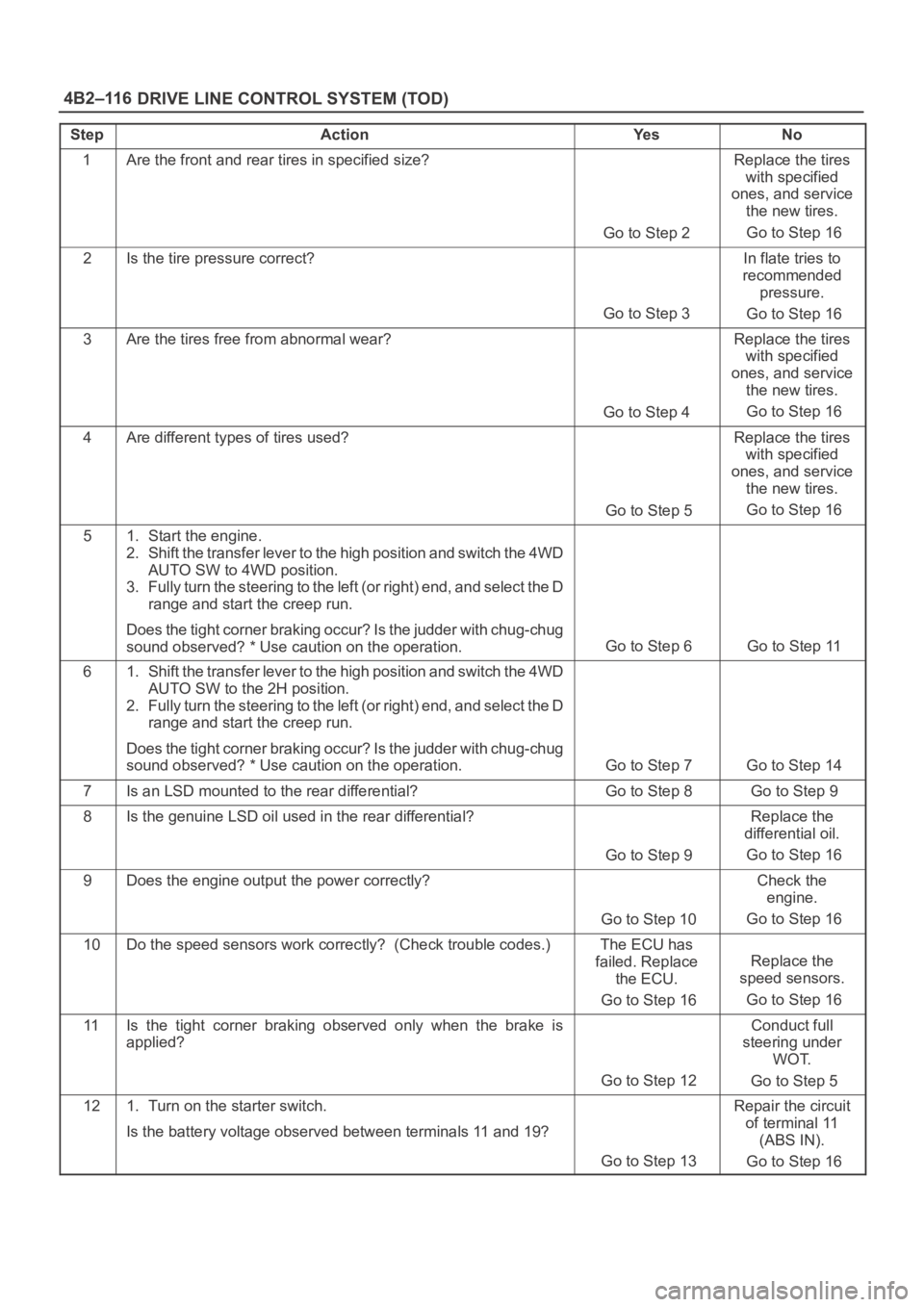
DRIVE LINE CONTROL SYSTEM (TOD) 4B2–116
StepActionYe sNo
1Are the front and rear tires in specified size?
Go to Step 2
Replace the tires
with specified
ones, and service
the new tires.
Go to Step 16
2Is the tire pressure correct?
Go to Step 3
In flate tries to
recommended
pressure.
Go to Step 16
3Are the tires free from abnormal wear?
Go to Step 4
Replace the tires
with specified
ones, and service
the new tires.
Go to Step 16
4Are different types of tires used?
Go to Step 5
Replace the tires
with specified
ones, and service
the new tires.
Go to Step 16
51. Start the engine.
2. Shift the transfer lever to the high position and switch the 4WD
AUTO SW to 4WD position.
3. Fully turn the steering to the left (or right) end, and select the D
range and start the creep run.
Does the tight corner braking occur? Is the judder with chug-chug
sound observed? * Use caution on the operation.
Go to Step 6 Go to Step 11
61. Shift the transfer lever to the high position and switch the 4WD
AUTO SW to the 2H position.
2. Fully turn the steering to the left (or right) end, and select the D
range and start the creep run.
Does the tight corner braking occur? Is the judder with chug-chug
sound observed? * Use caution on the operation.
Go to Step 7 Go to Step 14
7Is an LSD mounted to the rear differential? Go to Step 8 Go to Step 9
8Is the genuine LSD oil used in the rear differential?
Go to Step 9
Replace the
differential oil.
Go to Step 16
9Does the engine output the power correctly?
Go to Step 10
Check the
engine.
Go to Step 16
10Do the speed sensors work correctly? (Check trouble codes.)The ECU has
failed. Replace
the ECU.
Go to Step 16
Replace the
speed sensors.
Go to Step 16
11Is the tight corner braking observed only when the brake is
applied?
Go to Step 12
Conduct full
steering under
WOT.
Go to Step 5
121. Turn on the starter switch.
Is the battery voltage observed between terminals 11 and 19?
Go to Step 13
Repair the circuit
of terminal 11
(ABS IN).
Go to Step 16
Page 4210 of 6000
4C–4
DRIVE SHAFT SYSTEM
Rear Axle Shaft
Rear Axle Shaft and Associated Parts
420RW014
Legend
(1) Brake Caliper
(2) Brake Disc
(3) Wheel Pin
(4) Axle Shaft Assembly
(5) Back Plate
(6) Parking Brake Assembly
(7) Bearing Holder(8) Bearing
(9) Retainer
(10) Snap Ring
(11) Bolt
(12) Nut
(13) Antilock Brake System (ABS) Speed Sensor (if
so equipped)
Removal
1. Raise the vehicle.
2. Remove tires and wheels. Refer to Wheel in Steering
section.3. Remove brake caliper. Use a wire to attach the brake
caliper to the frame. Refer to Disk Brakes in Brake
section.
4. Remove brake disc.
5. Remove ABS sensor (if so equipped).
6. Remove Parking brake assembly. Refer to Parking
Brakes in Brake section.
Page 4213 of 6000
4C–7 DRIVE SHAFT SYSTEM
9. Fix the parking brake cable mounting bolt (Behind the
back plate).
10. Install parking brake assembly, refer to Parking
Brakes in Brake section.
11. Install antilock brake system sensor (if so equipped).
12. Install brake disc.
13. Install brake caliper, refer to Disk Brakes in Brake
section.
Page 4215 of 6000
4C–9 DRIVE SHAFT SYSTEM
Front Hub and Disc (with Shift on the Fly)
Disassembled View
411RW001
Legend
(1) Bolt
(2) Cap
(3) Snap Ring and Shim
(4) Hub Flange
(5) Lock Washer and Lock Screw
(6) Hub Nut(7) Outer Bearing
(8) Bolt
(9) Hub and Disc Assembly
(10) Wheel Pin
(11) ABS Sensor Ring (If equipped)
(12) Inner Bearing
(13) Oil Seal
Disassembly
1. Before disassembly, select the 2WD position.
2. Jack up the front of vehicle and support frame with
jack stands.3. Remove the disc brake caliper assembly and hang it
on the frame with wires. Refer to Front Disc Brake
Caliper Assembly in Brakes section.
4. Remove bolt.
5. Remove cap.
6. Remove snap ring and shim.
7. Remove hub flange.