1998 OPEL FRONTERA lock
[x] Cancel search: lockPage 3366 of 6000
SECURITY AND LOCKS8H–27
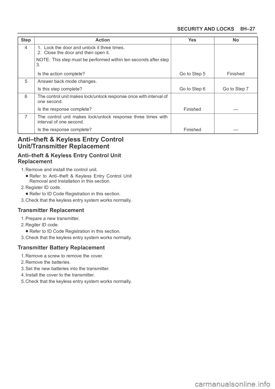
StepNo Ye s Action
41. Lock the door and unlock it three times.
2. Close the door and then open it.
NOTE: This step must be performed within ten seconds after step
3.
Is the action complete?
Go to Step 5Finished
5Answer back mode changes.
Is this step complete?
Go to Step 6Go to Step 7
6The control unit makes lock/unlock response once with interval of
one second.
Is the response complete?
Finished—
7The control unit makes lock/unlock response three times with
interval of one second.
Is the response complete?
Finished—
Anti–theft & Keyless Entry Control
Unit/Transmitter Replacement
Anti–theft & Keyless Entry Control Unit
Replacement
1. Remove and install the control unit.
Refer to Anti–theft & Keyless Entry Control Unit
Removal and Installation in this section.
2. Register ID code.
Refer to ID Code Registration in this section.
3. Check that the keyless entry system works normally.
Transmitter Replacement
1. Prepare a new transmitter.
2. Regiter ID code.
Refer to ID Code Registration in this section.
3. Check that the keyless entry system works normally.
Transmitter Battery Replacement
1. Remove a screw to remove the cover.
2. Remove the batteries.
3. Set the new batteries into the transmitter.
4. Install the cover to the transmitter.
5. Check that the keyless entry system works normally.
Page 3367 of 6000
8H–28SECURITY AND LOCKS
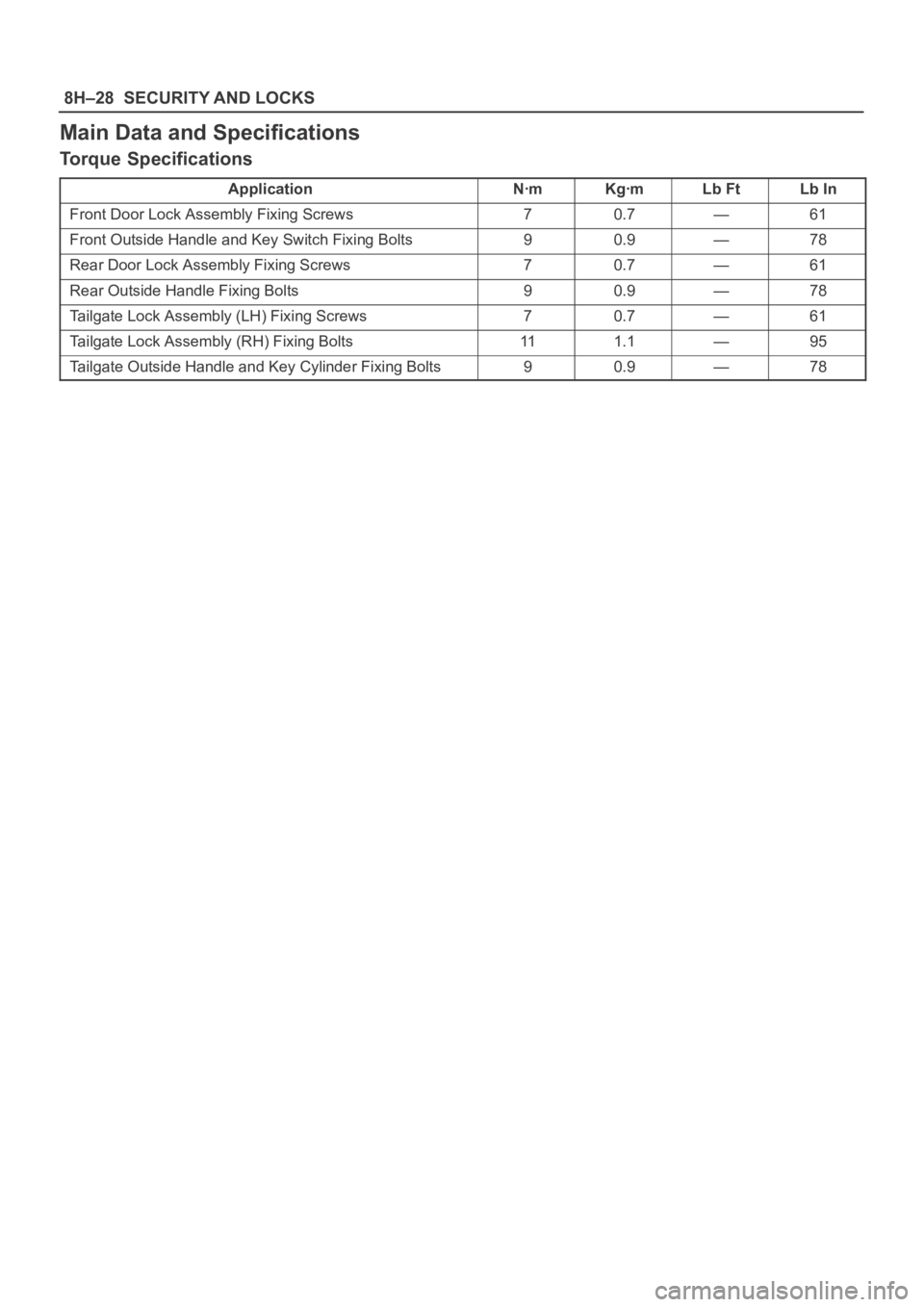
Main Data and Specifications
Torque Specifications
ApplicationNꞏmKgꞏmLb FtLb In
Front Door Lock Assembly Fixing Screws70.7—61
Front Outside Handle and Key Switch Fixing Bolts90.9—78
Rear Door Lock Assembly Fixing Screws70.7—61
Rear Outside Handle Fixing Bolts90.9—78
Tailgate Lock Assembly (LH) Fixing Screws70.7—61
Tailgate Lock Assembly (RH) Fixing Bolts111.1—95
Tailgate Outside Handle and Key Cylinder Fixing Bolts90.9—78
Page 3368 of 6000
SUN ROOF/CONVERTIBLE TOP8I–1
BODY AND ACCESSORIES
SUN ROOF/CONVERTIBLE TOP
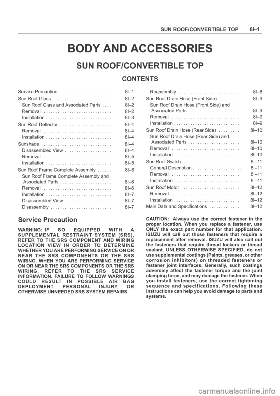
CONTENTS
Service Precaution 8I–1. . . . . . . . . . . . . . . . . . . . . .
Sun Roof Glass 8I–2. . . . . . . . . . . . . . . . . . . . . . . . .
Sun Roof Glass and Associated Parts 8I–2. . . .
Removal 8I–2. . . . . . . . . . . . . . . . . . . . . . . . . . . . .
Installation 8I–3. . . . . . . . . . . . . . . . . . . . . . . . . . . .
Sun Roof Deflector 8I–4. . . . . . . . . . . . . . . . . . . . . .
Removal 8I–4. . . . . . . . . . . . . . . . . . . . . . . . . . . . .
Installation 8I–4. . . . . . . . . . . . . . . . . . . . . . . . . . . .
Sunshade 8I–4. . . . . . . . . . . . . . . . . . . . . . . . . . . . . .
Disassembled View 8I–4. . . . . . . . . . . . . . . . . . . .
Removal 8I–5. . . . . . . . . . . . . . . . . . . . . . . . . . . . .
Installation 8I–5. . . . . . . . . . . . . . . . . . . . . . . . . . . .
Sun Roof Frame Complete Assembly 8I–6. . . . . .
Sun Roof Frame Complete Assembly and
Associated Parts 8I–6. . . . . . . . . . . . . . . . . . . . . .
Removal 8I–6. . . . . . . . . . . . . . . . . . . . . . . . . . . . .
Installation 8I–7. . . . . . . . . . . . . . . . . . . . . . . . . . . .
Disassembled View 8I–7. . . . . . . . . . . . . . . . . . . .
Disassembly 8I–7. . . . . . . . . . . . . . . . . . . . . . . . . . Reassembly 8I–8. . . . . . . . . . . . . . . . . . . . . . . . . .
Sun Roof Drain Hose (Front Side) 8I–9. . . . . . . . .
Sun Roof Drain Hose (Front Side) and
Associated Parts 8I–9. . . . . . . . . . . . . . . . . . . . . .
Removal 8I–9. . . . . . . . . . . . . . . . . . . . . . . . . . . . .
Installation 8I–9. . . . . . . . . . . . . . . . . . . . . . . . . . . .
Sun Roof Drain Hose (Rear Side) 8I–10. . . . . . . . .
Sun Roof Drain Hose (Rear Side) and
Associated Parts 8I–10. . . . . . . . . . . . . . . . . . . . . .
Removal 8I–10. . . . . . . . . . . . . . . . . . . . . . . . . . . . .
Installation 8I–10. . . . . . . . . . . . . . . . . . . . . . . . . . . .
Sun Roof Switch 8I–11. . . . . . . . . . . . . . . . . . . . . . . .
General Description 8I–11. . . . . . . . . . . . . . . . . . . . . .
Removal 8I–11. . . . . . . . . . . . . . . . . . . . . . . . . . . . .
Installation 8I–11. . . . . . . . . . . . . . . . . . . . . . . . . . . .
Sun Roof Motor 8I–12. . . . . . . . . . . . . . . . . . . . . . . . .
Removal 8I–12. . . . . . . . . . . . . . . . . . . . . . . . . . . . .
Installation 8I–12. . . . . . . . . . . . . . . . . . . . . . . . . . . .
Main Data and Specifications 8I–12. . . . . . . . . . . . .
Service Precaution
WARNING: IF SO EQUIPPED WITH A
SUPPLEMENTAL RESTRAINT SYSTEM (SRS),
REFER TO THE SRS COMPONENT AND WIRING
LOCATION VIEW IN ORDER TO DETERMINE
WHETHER YOU ARE PERFORMING SERVICE ON OR
NEAR THE SRS COMPONENTS OR THE SRS
WIRING. WHEN YOU ARE PERFORMING SERVICE
ON OR NEAR THE SRS COMPONENTS OR THE SRS
WIRING, REFER TO THE SRS SERVICE
INFORMATION. FAILURE TO FOLLOW WARNINGS
COULD RESULT IN POSSIBLE AIR BAG
DEPLOYMENT, PERSONAL INJURY, OR
OTHERWISE UNNEEDED SRS SYSTEM REPAIRS.CAUTION: Always use the correct fastener in the
proper location. When you replace a fastener, use
ONLY the exact part number for that application.
ISUZU will call out those fasteners that require a
replacement after removal. ISUZU will also call out
the fasteners that require thread lockers or thread
sealant. UNLESS OTHERWISE SPECIFIED, do not
use supplemental coatings (Paints, greases, or other
corrosion inhibitors) on threaded fasteners or
fastener joint interfaces. Generally, such coatings
adversely affect the fastener torque and the joint
clamping force, and may damage the fastener. When
you install fasteners, use the correct tightening
sequence and specifications. Following these
instructions can help you avoid damage to parts and
systems.
Page 3381 of 6000
8J–2EXTERIOR/INTERIOR TRIM
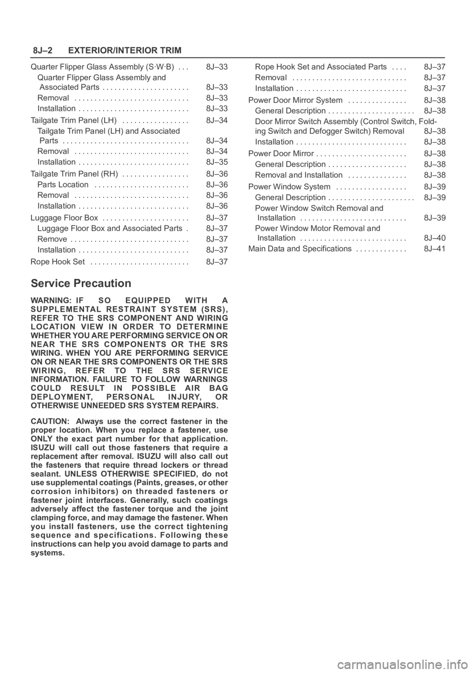
Quarter Flipper Glass Assembly (SꞏWꞏB) 8J–33. . .
Quarter Flipper Glass Assembly and
Associated Parts 8J–33. . . . . . . . . . . . . . . . . . . . . .
Removal 8J–33. . . . . . . . . . . . . . . . . . . . . . . . . . . . .
Installation 8J–33. . . . . . . . . . . . . . . . . . . . . . . . . . . .
Tailgate Trim Panel (LH) 8J–34. . . . . . . . . . . . . . . . .
Tailgate Trim Panel (LH) and Associated
Parts 8J–34. . . . . . . . . . . . . . . . . . . . . . . . . . . . . . . .
Removal 8J–34. . . . . . . . . . . . . . . . . . . . . . . . . . . . .
Installation 8J–35. . . . . . . . . . . . . . . . . . . . . . . . . . . .
Tailgate Trim Panel (RH) 8J–36. . . . . . . . . . . . . . . . .
Parts Location 8J–36. . . . . . . . . . . . . . . . . . . . . . . .
Removal 8J–36. . . . . . . . . . . . . . . . . . . . . . . . . . . . .
Installation 8J–36. . . . . . . . . . . . . . . . . . . . . . . . . . . .
Luggage Floor Box 8J–37. . . . . . . . . . . . . . . . . . . . . .
Luggage Floor Box and Associated Parts 8J–37.
Remove 8J–37. . . . . . . . . . . . . . . . . . . . . . . . . . . . . .
Installation 8J–37. . . . . . . . . . . . . . . . . . . . . . . . . . . .
Rope Hook Set 8J–37. . . . . . . . . . . . . . . . . . . . . . . . . Rope Hook Set and Associated Parts 8J–37. . . .
Removal 8J–37. . . . . . . . . . . . . . . . . . . . . . . . . . . . .
Installation 8J–37. . . . . . . . . . . . . . . . . . . . . . . . . . . .
Power Door Mirror System 8J–38. . . . . . . . . . . . . . .
General Description 8J–38. . . . . . . . . . . . . . . . . . . . . .
Door Mirror Switch Assembly (Control Switch, Fold-
ing Switch and Defogger Switch) Removal 8J–38
Installation 8J–38. . . . . . . . . . . . . . . . . . . . . . . . . . . .
Power Door Mirror 8J–38. . . . . . . . . . . . . . . . . . . . . . .
General Description 8J–38. . . . . . . . . . . . . . . . . . . .
Removal and Installation 8J–38. . . . . . . . . . . . . . .
Power Window System 8J–39. . . . . . . . . . . . . . . . . .
General Description 8J–39. . . . . . . . . . . . . . . . . . . . . .
Power Window Switch Removal and
Installation 8J–39. . . . . . . . . . . . . . . . . . . . . . . . . . .
Power Window Motor Removal and
Installation 8J–40. . . . . . . . . . . . . . . . . . . . . . . . . . .
Main Data and Specifications 8J–41. . . . . . . . . . . . .
Service Precaution
WARNING: IF SO EQUIPPED WITH A
SUPPLEMENTAL RESTRAINT SYSTEM (SRS),
REFER TO THE SRS COMPONENT AND WIRING
LOCATION VIEW IN ORDER TO DETERMINE
WHETHER YOU ARE PERFORMING SERVICE ON OR
NEAR THE SRS COMPONENTS OR THE SRS
WIRING. WHEN YOU ARE PERFORMING SERVICE
ON OR NEAR THE SRS COMPONENTS OR THE SRS
WIRING, REFER TO THE SRS SERVICE
INFORMATION. FAILURE TO FOLLOW WARNINGS
COULD RESULT IN POSSIBLE AIR BAG
DEPLOYMENT, PERSONAL INJURY, OR
OTHERWISE UNNEEDED SRS SYSTEM REPAIRS.
CAUTION: Always use the correct fastener in the
proper location. When you replace a fastener, use
ONLY the exact part number for that application.
ISUZU will call out those fasteners that require a
replacement after removal. ISUZU will also call out
the fasteners that require thread lockers or thread
sealant. UNLESS OTHERWISE SPECIFIED, do not
use supplemental coatings (Paints, greases, or other
corrosion inhibitors) on threaded fasteners or
fastener joint interfaces. Generally, such coatings
adversely affect the fastener torque and the joint
clamping force, and may damage the fastener. When
you install fasteners, use the correct tightening
sequence and specifications. Following these
instructions can help you avoid damage to parts and
systems.
Page 3387 of 6000
8J–8EXTERIOR/INTERIOR TRIM
632RW001
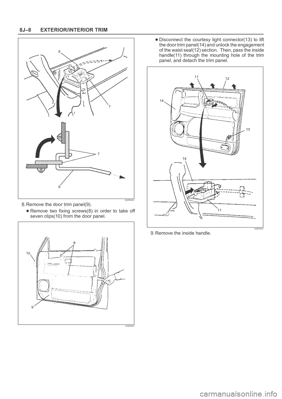
8. Remove the door trim panel(9).
Remove two fixing screws(8) in order to take off
seven clips(10) from the door panel.
635RS007
Disconnect the courtesy light connector(13) to lift
the door trim panel(14) and unlock the engagement
of the waist seal(12) section. Then, pass the inside
handle(11) through the mounting hole of the trim
panel, and detach the trim panel.
632RS015
9. Remove the inside handle.
Page 3390 of 6000
EXTERIOR/INTERIOR TRIM8J–11
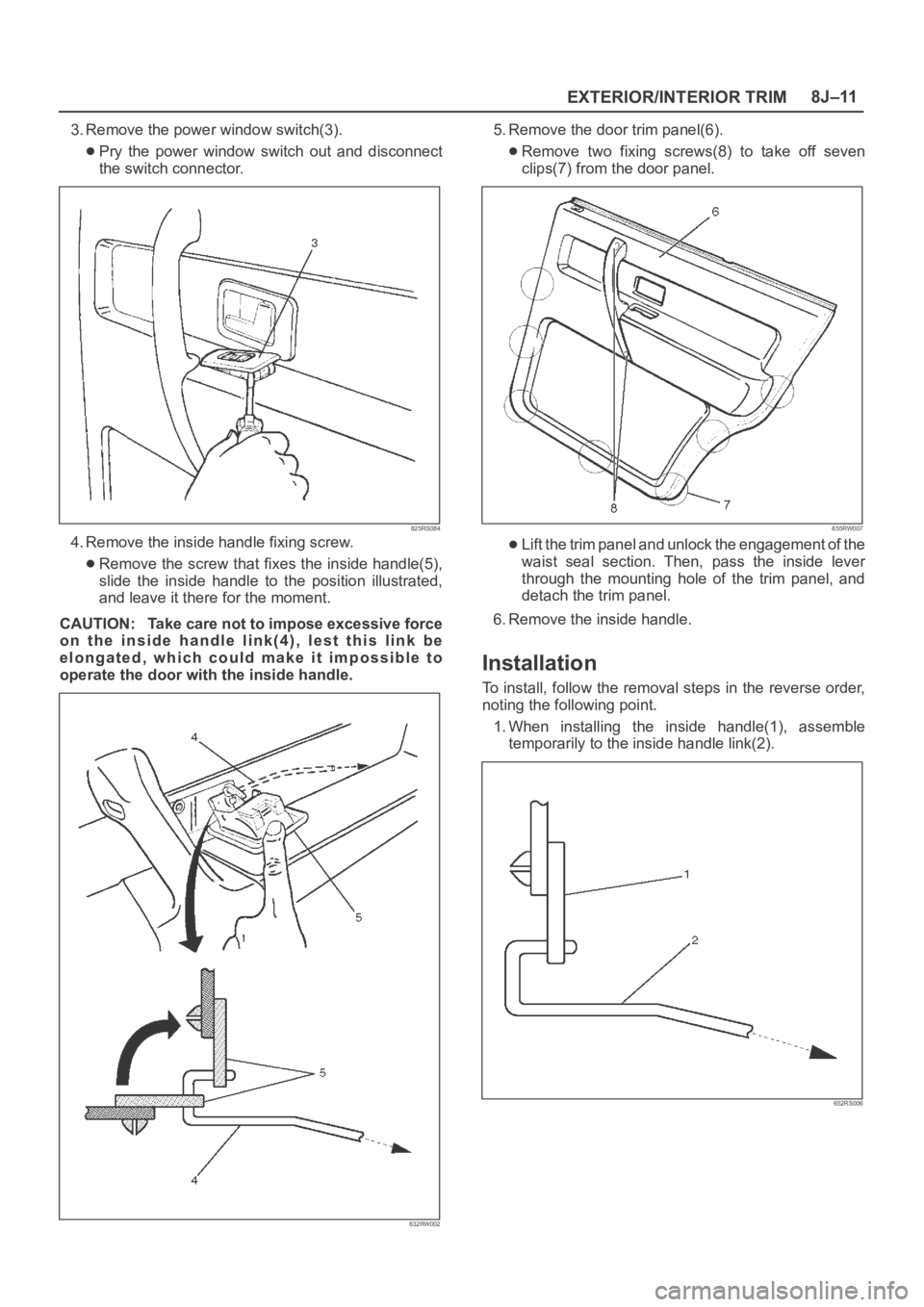
3. Remove the power window switch(3).
Pry the power window switch out and disconnect
the switch connector.
825RS084
4. Remove the inside handle fixing screw.
Remove the screw that fixes the inside handle(5),
slide the inside handle to the position illustrated,
and leave it there for the moment.
CAUTION: Take care not to impose excessive force
on the inside handle link(4), lest this link be
elongated, which could make it impossible to
operate the door with the inside handle.
632RW002
5. Remove the door trim panel(6).
Remove two fixing screws(8) to take off seven
clips(7) from the door panel.
655RW007
Lift the trim panel and unlock the engagement of the
waist seal section. Then, pass the inside lever
through the mounting hole of the trim panel, and
detach the trim panel.
6. Remove the inside handle.
Installation
To install, follow the removal steps in the reverse order,
noting the following point.
1. When installing the inside handle(1), assemble
temporarily to the inside handle link(2).
652RS006
Page 3417 of 6000
8J–38EXTERIOR/INTERIOR TRIM
Power Door Mirror System
General Description
The circuit consists of the starter switch, door mirror
control switch, folding switch, defogger switch and door
mirrors on both sides.
The door mirror switch consists of the control switch,
folding switch and defogger switch.
When the control switch is operated with the starter
switch at either “ACC” or “ON” position, the motors
incorporated in the door mirrors on both sides rotates to
allow the horizontal and vertical adjustment of mirror
angles.
The folding switch can be used to fold the mirror and
return it to its original position.
When turning on the door mirror defogger switch with the
starter switch at “ON” position, built-in heater in the mirror
is activated to perform the defogger function.
Door Mirror Switch Assembly (Con-
trol Switch, Folding Switch and De-
fogger Switch) Removal
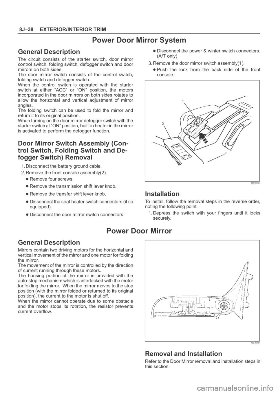
1. Disconnect the battery ground cable.
2. Remove the front console assembly(2).
Remove four screws.
Remove the transmission shift lever knob.
Remove the transfer shift lever knob.
Disconnect the seat heater switch connectors (if so
equipped).
Disconnect the door mirror switch connectors.
Disconnect the power & winter switch connectors.
(A/T only)
3. Remove the door mirror switch assembly(1).
Push the lock from the back side of the front
console.
825RS005
Installation
To install, follow the removal steps in the reverse order,
noting the following point.
1. Depress the switch with your fingers until it locks
securely.
Power Door Mirror
General Description
Mirrors contain two driving motors for the horizontal and
vertical movement of the mirror and one motor for folding
the mirror.
The movement of the mirror is controlled by the direction
of current running through these motors.
The housing portion of the mirror is provided with the
auto-stop mechanism which is interlocked with the motor
for folding the mirror. When the mirror moves to the stop
position (with the mirror folded or returned to its original
position), the current to the motor is shut off.
When the mirror cannot operate due to some obstacle
and the motor stops its rotation, the resistor prevents
current overflow.
720RS004
Removal and Installation
Refer to the Door Mirror removal and installation steps in
this section.
Page 3418 of 6000
EXTERIOR/INTERIOR TRIM8J–39
Power Window System
General Description
The circuit consists of the starter switch, (door lock &)
power window switch for each of the front windows,
p o w e r w i n d o w s w i t c h f o r r e a r w i n d o w s a n d p o w e r w i n d o w
motors.
When the starter switch is turned on, the battery voltage is
applied to each of the power window switches through the
circuit breaker and the power window relay on the circuit.
The “Down” switch of the driver’s power window switch
has a built-in function which can be operated by just
touching it.
Accordingly, the window will roll down automatically by
just setting the switch to the “AUTO” position.
When the driver’s power lock switch at the driver side is
depressed, the power source to the passenger’s power
window switches are shut off. So, even if these switches
are operated, the power window motor will not operate.
Power Window Switch Removal and
Installation
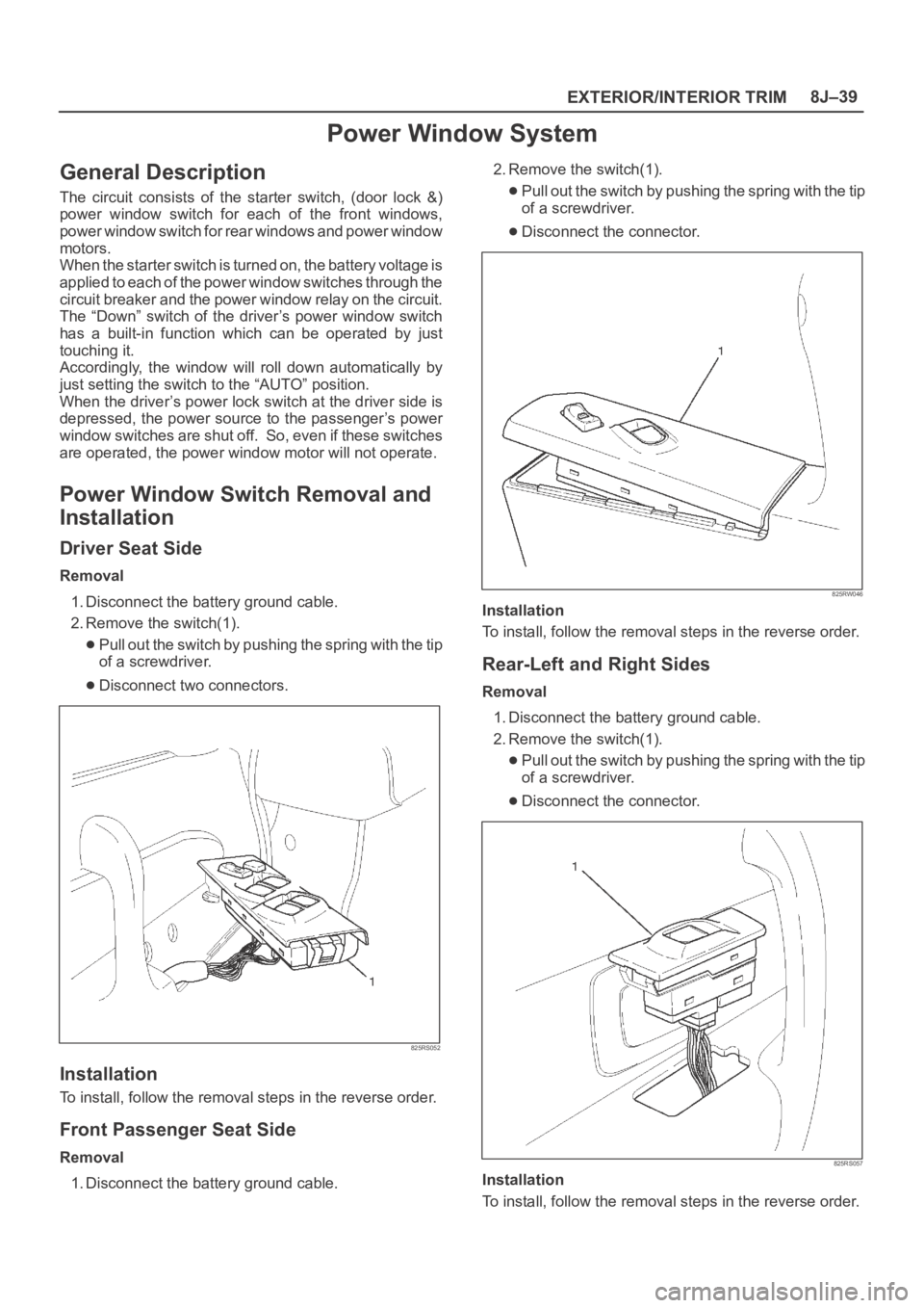
Driver Seat Side
Removal
1. Disconnect the battery ground cable.
2. Remove the switch(1).
Pull out the switch by pushing the spring with the tip
of a screwdriver.
Disconnect two connectors.
825RS052
Installation
To install, follow the removal steps in the reverse order.
Front Passenger Seat Side
Removal
1. Disconnect the battery ground cable.2. Remove the switch(1).
Pull out the switch by pushing the spring with the tip
of a screwdriver.
Disconnect the connector.
825RW046
Installation
To install, follow the removal steps in the reverse order.
Rear-Left and Right Sides
Removal
1. Disconnect the battery ground cable.
2. Remove the switch(1).
Pull out the switch by pushing the spring with the tip
of a screwdriver.
Disconnect the connector.
825RS057
Installation
To install, follow the removal steps in the reverse order.